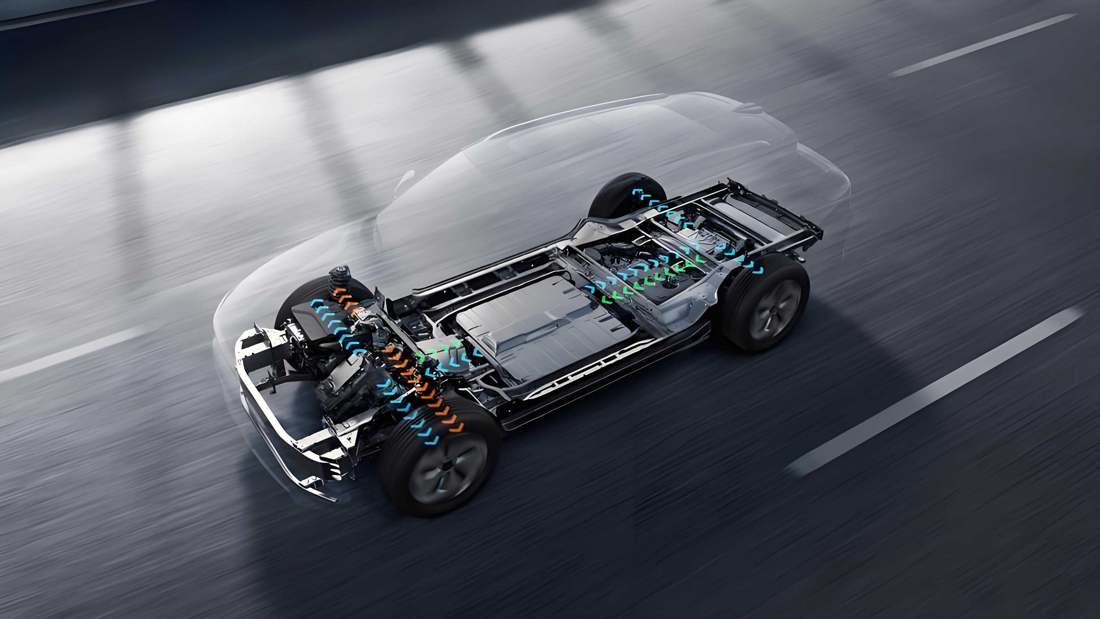
As an engineer deeply involved in electric vehicle (EV) chassis safety, I witness firsthand the critical role of brake-by-wire (BBW) systems in enabling autonomous driving. The shift from mechanical to electronic control demands unprecedented reliability, where redundancy is no longer optional but foundational. This article synthesizes the current landscape and future trajectory of BBW redundancy, focusing on electric vehicle applications.

1. The Imperative for Redundancy in Electric Vehicles
BBW systems replace traditional hydraulic/mechanical linkages with electronic controls and actuators. For electric vehicles, this enables:
- Regenerative braking integration
- Faster response times (<150 ms vs. 400 ms in conventional brakes)
- Precision control for stability functions (ABS, ESC, TCS)
However, single-point failures in electronics pose severe safety risks. Redundancy ensures continued braking capability during failures, quantified by the functional safety metric:
\lambda_{DU} \leq 10^{-8} \text{ failures/hour} \quad (\text{ASIL D})
where $\lambda_{DU}$ is the rate of undetected dangerous failures.
2. Redundant Architectures: EHB Systems
Electro-Hydraulic Brake (EHB) systems dominate due to hydraulic fallback. Two primary topologies exist:
2.1 Two-Box Solutions
Separate units for brake boost (e.g., iBooster) and stability control (e.g., ESP). Redundancy emerges naturally:
- Primary Path: iBooster generates hydraulic pressure.
- Secondary Path: ESP takes over during iBooster failure.
*Table 1: Two-Box Redundancy Comparison*
| Supplier/System | Redundancy Mechanism | Max Deceleration (g) |
|---|---|---|
| Bosch iBooster+ESP | Mutual backup; ESP active pressure build-up | 0.3 |
| Asia-Pacific IBS | ESC as backup for IBS pressure unit | 0.4 |
Failure Response Workflow:
- ECU detects primary actuator failure.
- Control switches to secondary actuator within <100 ms.
- Hydraulic valves reconfigure to enable backup pressure source.
2.2 One-Box Solutions
Integrated units (e.g., Bosch IPB, Continental MK-C1) combine boost and stability control. Redundancy requires added layers:
- Hydraulic Fallback: Mechanical link to pedal enables ~0.5g deceleration.
- Electronic Redundancy: Requires Redundant Brake Unit (RBU).
*Table 2: One-Box Redundancy Strategies*
| Supplier/System | Redundancy Approach | Autonomy Level Support |
|---|---|---|
| Bosch IPB + RBU | RBU with 2-in/2-out valve blocks | L3+ |
| Continental MK-C1+HBE | HBE module for 60% deceleration backup | L3 |
| EMB-EHB Hybrid | Distributed motors + hydraulic backup per wheel | L4 (experimental) |
The RBU’s role is defined by the pressure continuity equation during failure:
P_{\text{backup}} = \frac{F_{\text{driver}} \cdot \eta_{\text{mech}}}}{A_{\text{mc}}}}
where $F_{\text{driver}}$ is pedal force, $\eta_{\text{mech}}$ is mechanical efficiency, and $A_{\text{mc}}$ is master cylinder area.
3. Redundant Architectures: EMB Systems
Electro-Mechanical Brake (EMB) systems eliminate hydraulics, using motors per wheel. Redundancy shifts to distributed control:
3.1 Topology
- Four independent motor-calipers.
- Central ECU + domain controllers.
- Brake pedal emulator with dual sensors.
3.2 Redundancy Models
- Component-Level: Dual-wound motors, redundant position sensors.
- System-Level: Cross-wheel backup (3-wheel braking if one fails).
- Power-Level: Dual 12V rails or 48V+12V hybrid.
Table 3: EMB Redundancy Implementation
| Supplier/System | Redundancy Features | Response Time (ms) |
|---|---|---|
| Brembo EMB | Front hydraulic backup + rear EMB | 90 |
| Great Wall Triple-Redundancy | Triple-redundant sensors, controllers, power | 80 |
Key advantage: EMB enables per-wheel force optimization for stability:
F_{x,i} = K \cdot \mu_i \cdot F_{z,i}
where $F_{x,i}$ is braking force, $\mu_i$ is friction coefficient, and $F_{z,i}$ is vertical load at wheel $i$.
4. Multi-Layer Redundancy Framework
For L3+ electric vehicles, redundancy spans:
- Power: Dual batteries with isolation diodes.
- Sensors: Signal voting (e.g., 2-out-of-3 encoders).
- Controllers: Lockstep CPUs or heterogeneous SoCs.
- Actuators: Dual-coil motors or hybrid EMB-EHB.
*Table 4: Multi-Layer Redundancy Standards*
| Layer | Requirement | Example Solutions |
|---|---|---|
| Power | Uninterrupted 12V/48V supply | Dual batteries + supercapacitors |
| Communication | Dual CAN FD or Ethernet | Ring topology with heartbeat signals |
| Control | ASIL-D decomposed ECUs | NXP S32K/Infineon Aurix TC4x |
| Actuation | Force diversity (EMB + regen + hydraulic) | EMB + 70% regen + mechanical link |
Fault detection employs cross-monitoring algorithms:
\text{Fault Flag} = \begin{cases}
1 & \text{if } |\tau_{\text{cmd}} - \tau_{\text{meas}}| \geq \epsilon \\
0 & \text{otherwise}
\end{cases}
where $\tau$ is motor torque and $\epsilon$ is tolerance threshold.
5. Regenerative Braking Integration
Electric vehicles uniquely leverage regen as a redundancy layer. Coordination logic must:
- Blend friction/regen seamlessly.
- Prioritize regen during primary brake failure.
- Ensure torque consistency:math复制下载T_{\text{total}} = T_{\text{regen}}} + T_{\text{friction}}
Regen Redundancy Constraints:
- Limited by battery SOC/temperature.
- Requires inverter-motor backup (e.g., dual IGBTs).
6. Future Directions
- EMB Dominance: Eliminating hydraulics reduces weight by ~5 kg per electric vehicle.
- Domain Fusion: Integration with steering/suspension controllers.
- AI-Driven Fault Prediction: Using motor current signatures to preempt failures.
- Standardization: ISO 26262 updates for multi-path redundancy.
7. Conclusion
Redundancy in electric vehicle BBW systems evolves from simple duplication to heterogeneous multi-layer architectures. EHB offers near-term safety with hydraulic fallback, while EMB promises long-term gains via distributed intelligence. As autonomy advances, the fusion of EMB, regen, and predictive controls will define the next generation of electric vehicle safety.
