1. Introduction
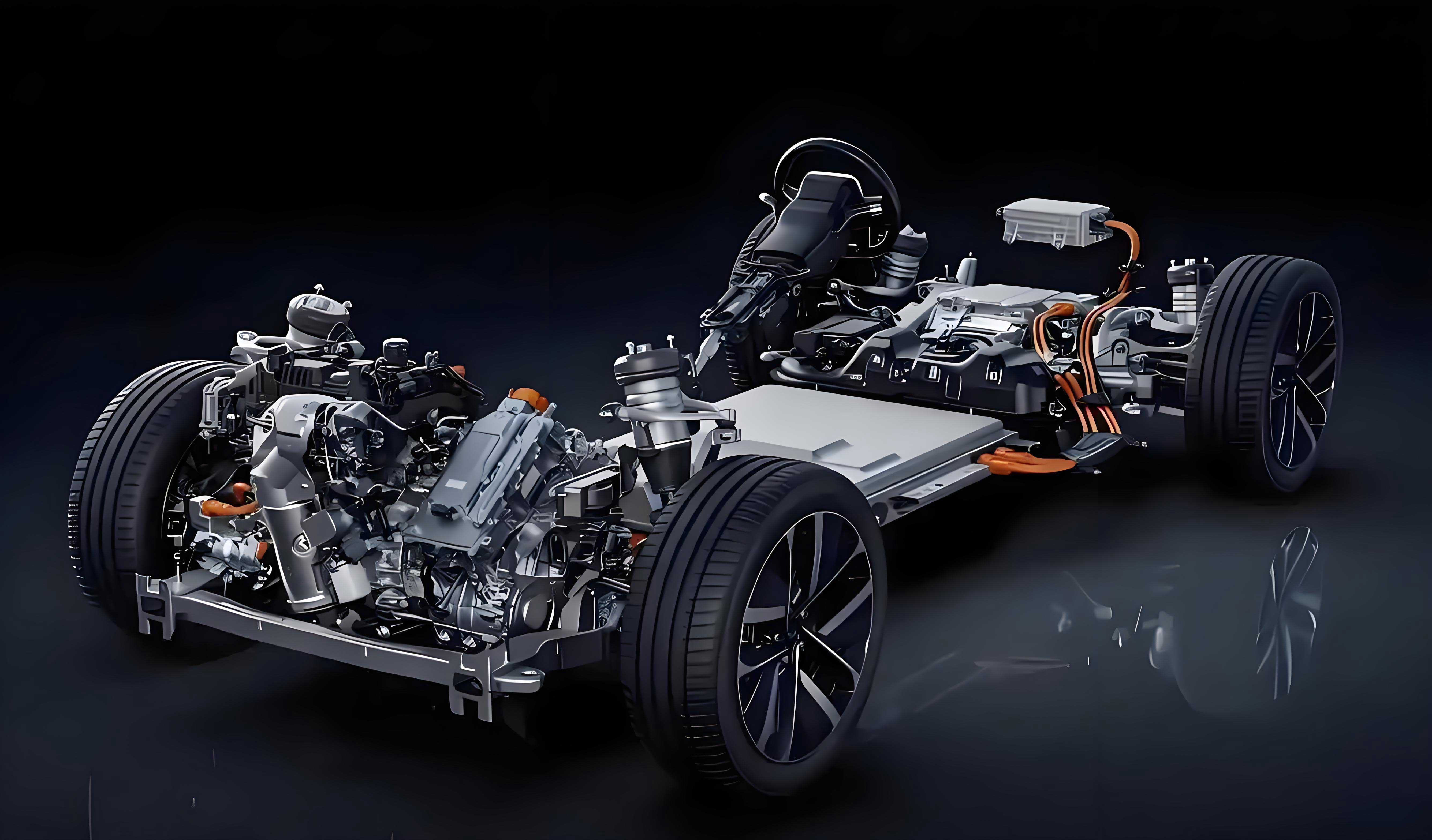
The escalating energy crisis and environmental concerns have propelled distributed drive electric vehicles (EVs) to the forefront of automotive research. These vehicles leverage independent control of four-wheel torque, enabling simultaneous optimization of braking stability and energy recovery. This study proposes a novel hierarchical composite braking control strategy that integrates yaw stability management with regenerative braking efficiency, capitalizing on the unique actuation capabilities of distributed drive EVs.

2. Hierarchical Control Framework
The strategy employs a two-tier architecture:
- Upper-Level Controller: Computes total longitudinal braking force and corrective yaw moment.
- Lower-Level Controller: Optimizes wheel-specific motor/friction torque distribution.
2.1 Upper-Level Controller Design
2.1.1 Longitudinal Speed Tracking (PID Control)
The PID controller calculates braking intensity zz based on target vs. actual velocity error:z=Kp(vd−v)+Ki∫(vd−v)dt+Kdd(vd−v)dtz=Kp(vd−v)+Ki∫(vd−v)dt+Kddtd(vd−v)
Total longitudinal force: Fx=z⋅m⋅gFx=z⋅m⋅g.
Table 1: PID Parameters
| Parameter | Value | Description |
|---|---|---|
| KpKp | 1.2 | Proportional gain |
| KiKi | 0.05 | Integral gain |
| KdKd | 0.01 | Derivative gain |
2.1.2 Yaw Moment Control (Model Predictive Control)
The MPC tracks ideal yaw rate γdγd and sideslip angle βdβd derived from a 2-DOF vehicle model:βd=b−amvx2kr(a+b)1+Kvx2δ,γd=vx(a+b)(1+Kvx2)δβd=1+Kvx2b−kr(a+b)amvx2δ,γd=(a+b)(1+Kvx2)vxδ
where K=m(a+b)2(akf−bkr)K=(a+b)2m(kfa−krb).
Discretized state-space model:Δx(t+1)=A~Δx(t)+B~1Δu(t)+B~2Δw(t)Δx(t+1)=A~Δx(t)+B~1Δu(t)+B~2Δw(t)
Cost function minimizes tracking error and control effort:minJ(t)=∥Y(t)−W(t)∥Q2+∥ΔU(t)∥R2minJ(t)=∥Y(t)−W(t)∥Q2+∥ΔU(t)∥R2
Constraints:
- Actuator limits: umin≤u≤umaxumin≤u≤umax
- Yaw rate bounds: γmin≤γ≤γmaxγmin≤γ≤γmax
3. Lower-Level Controller: Torque Distribution
3.1 Tire Utilization Optimization
Minimize tire workload variance via quadratic programming:minJ=∑i=fl,fr,rl,rrFxi2(μFzi)2minJ=i=fl,fr,rl,rr∑(μFzi)2Fxi2
Subject to:
- Equality constraints:{Fx=∑FxiMz=D2(−Fxfl+Fxfr−Fxrl+Fxrr){Fx=∑FxiMz=2D(−Fxfl+Fxfr−Fxrl+Fxrr)
- Inequality constraints:Fxi≤min(Tmax,iRw,μFzi)Fxi≤min(RwTmax,i,μFzi)
Solved using the active-set method for computational efficiency.
3.2 Motor Braking Force Coefficient
A coefficient k=k1⋅k2⋅k3k=k1⋅k2⋅k3 modulates regenerative braking contribution:
- Braking intensity factor k1k1:k1={1z≤0.7 and Tmax≥TneedTmaxTneedz≤0.7 and Tmax<Tneed0z>0.7k1=⎩⎨⎧1TneedTmax0z≤0.7 and Tmax≥Tneedz≤0.7 and Tmax<Tneedz>0.7
- SOC factor k2k2:k2={1SOC<90%0SOC≥90%k2={10SOC<90%SOC≥90%
- Velocity factor k3k3:k3={0v≤5km/hv−555<v<10km/h1v≥10km/hk3=⎩⎨⎧05v−51v≤5km/h5<v<10km/hv≥10km/h
Motor torque per wheel: .
4. Simulation Results
Co-simulations in MATLAB/Simulink-CarSim under cornering braking scenarios.
Table 2: EV Parameters
| Parameter | Value | Unit |
|---|---|---|
| Mass mm | 1,230 | kg |
| Wheelbase LL | 2.6 | m |
| RwRw | 0.31 | m |
| IzIz | 1,343.1 | kg·m² |
| Motor peak torque | 350 | Nm |
4.1 Constant Braking Intensity (z=0.2z=0.2)
- Yaw stability: Optimized allocation reduced yaw rate error by 66.7% vs. rule-based allocation.
- Energy recovery: SOC increased by 0.103 (optimized) vs. 0.095 (rule-based).
Table 3: Performance Comparison (z=0.2z=0.2)
| Metric | Rule-Based | Optimized | Improvement |
|—————————-|————|———–|————-|
| Max yaw rate error (deg/s) | 0.93 | 0.31 | 66.7% |
| SOC increase | 0.095 | 0.103 | 8.4% |
4.2 Variable Braking Intensity (z:0.2→0.7z:0.2→0.7)
- Motor torque phased out at z>0.7z>0.7 (Figure 1a).
- SOC gain: 0.09 (optimized) vs. 0.05 (rule-based).
- Yaw rate error: 1.88 deg/s (optimized) vs. unstable (rule-based).
5. Conclusion
- Hierarchical Control: The integration of PID-based speed tracking and MPC-based yaw control ensures stability during cornering braking for electric vehicles.
- Energy Recovery: Adaptive motor torque allocation increases regenerative energy capture by 8.4–80% across scenarios.
- Real-World Applicability: Validated under variable braking intensities, confirming robustness for electric vehicle applications.
Future work includes hardware-in-the-loop validation and road testing.
Appendix: Key Nomenclature
| Symbol | Description |
|---|---|
| FxFx | Total longitudinal force |
| MzMz | Corrective yaw moment |
| SOC | Battery state of charge |
| ββ | Sideslip angle |
| γγ | Yaw rate |
| μμ | Tire-road friction coefficient |
