
The powertrain battery system constitutes the cornerstone of modern electric vehicles (EVs), directly determining critical performance metrics such as range, acceleration, longevity, and safety. A profound understanding of its key performance indicators, structural composition, cell configuration methodologies, and management systems is paramount for engineers and technicians working within the rapidly evolving EV landscape.
1. Core Performance Parameters of EV Batteries
The operational effectiveness and limitations of an EV battery are defined by a suite of interrelated performance parameters:
- Voltage Parameters:
- Open Circuit Voltage (OCV): The voltage measured across the battery terminals when no external circuit is connected (no current flow). OCV correlates with the battery’s State of Charge (SOC) and is fundamental for onboard charge estimation systems.
- Working Voltage: The voltage measured across the battery terminals during operation (when current is flowing). Due to internal resistance, the working voltage during discharge is always lower than the OCV, and during charging, it is higher.
- Discharge Cut-off Voltage: The minimum safe voltage threshold during discharge. Discharging beyond this point constitutes over-discharge, causing significant damage to cell chemistry, capacity, and lifespan.
- Charge Limit Voltage: The maximum safe voltage threshold during charging. Charging typically transitions from constant current (CC) to constant voltage (CV) mode once this voltage is reached to prevent overcharging.
- Capacity (C): This denotes the total electrical charge a battery can store and deliver, measured in Ampere-hours (Ah) or milliampere-hours (mAh). It is a primary indicator of the battery’s energy storage capability, primarily determined by the quantity and quality of active materials within the electrodes. Capacity is calculated as:
C = I * t
Where:C= Capacity (Ah)I= Discharge Current (A)t= Discharge Time (h)- Example: A 10 Ah battery can theoretically deliver 5A for 2 hours or 10A for 1 hour under ideal conditions. Actual capacity depends on discharge rate, temperature, age, and utilization efficiency of the active materials.
- Energy & Energy Density: Energy (Wh) represents the total electrical energy a battery can deliver, calculated as:
Energy (Wh) = Nominal Voltage (V) * Capacity (Ah)
Energy Density, expressed as Wh/kg (gravimetric) or Wh/L (volumetric), measures the energy stored per unit mass or volume. This parameter is the critical factor determining an electric vehicle’s driving range. Higher energy density translates directly to longer range for a given battery weight or size. - Power & Power Density: Power (W) indicates the rate at which a battery can deliver energy. Power Density (W/kg or W/L) measures power output per unit mass or volume. This parameter governs the electric vehicle’s acceleration performance and regenerative braking capability. High power density enables rapid discharge for acceleration and rapid charge acceptance during braking.
- C-Rate: This signifies the charge or discharge current relative to the battery’s nominal capacity. It is defined as:
C-Rate = I / C
Where:I= Charge or Discharge Current (A)C= Nominal Capacity (Ah)- Example: A 1C rate for a 100Ah battery corresponds to a 100A current. A 0.5C discharge rate would be 50A. High C-rates are required for acceleration and fast charging but generate more heat and stress.
- State of Charge (SOC): Expressed as a percentage (0% to 100%), SOC represents the available capacity remaining in the battery relative to its fully charged capacity. Accurate SOC estimation by the Battery Management System (BMS) is crucial for range prediction, preventing overcharge/over-discharge, and optimizing battery usage. SOC is the central parameter managed by the BMS.
- Internal Resistance (IR): This complex parameter represents the opposition to current flow within the battery during operation. It comprises Ohmic resistance (from materials, electrolytes, and connections) and Polarization resistance (from electrochemical reactions). Lower internal resistance is highly desirable:
- Higher working voltage under load (less voltage sag).
- Reduced energy loss as heat during charge/discharge, improving efficiency.
- Enables higher power delivery and acceptance (better acceleration/regeneration).
- Minimizes heat generation, slowing aging and improving safety.
High IR leads to excessive heat, accelerated aging, limited power, and reduced usable capacity, especially at high C-rates.
- Self-Discharge Rate: This refers to the gradual loss of charge when the battery is not in use (open circuit). A low self-discharge rate is essential for good shelf life and maintaining charge during vehicle storage. Higher self-discharge reduces available capacity over time.
- Depth of Discharge (DOD): This indicates the percentage of the battery’s capacity that has been discharged relative to its full capacity. For example, discharging a 10Ah battery to 2Ah represents 80% DOD. Shallower DOD cycles generally prolong battery life.
- Cycle Life: This is the number of complete charge-discharge cycles a battery can undergo before its capacity degrades to a specified percentage (often 70-80%) of its original capacity. Cycle life is heavily influenced by DOD, operating temperature, charge/discharge rates, and battery chemistry.
- Cell Consistency: Due to manufacturing tolerances, individual cells within a battery pack exhibit slight variations in capacity, internal resistance, and self-discharge rate. These initial differences can amplify over time and cycles, leading to pack imbalance. This imbalance reduces overall pack capacity, increases stress on individual cells, and shortens pack life. Battery packs incorporate BMS with cell balancing functionality to mitigate this issue.
- Formation: This is an initial conditioning process after cell manufacturing involving controlled low-current charging/discharging cycles. Formation stabilizes the electrode materials, forms the critical Solid Electrolyte Interphase (SEI) layer on the anode, and allows for performance screening and grading of cells to improve consistency within modules and packs. Formation capacity is a key quality control metric.
2. Lithium-Ion Battery Chemistries for Electric Vehicles
The choice of cathode material significantly impacts the performance, cost, safety, and application suitability of lithium-ion batteries used in electric vehicles. The dominant chemistries are compared below:
*Table 1: Comparison of Key Lithium-Ion Battery Cathode Chemistries for Electric Vehicles*
| Parameter | Lithium Cobalt Oxide (LCO) | Lithium Manganese Oxide (LMO) | Lithium Iron Phosphate (LFP) | Lithium Nickel Cobalt Manganese (NMC) | Lithium Nickel Cobalt Aluminum (NCA) |
|---|---|---|---|---|---|
| Chemical Formula | LiCoO₂ | LiMn₂O₄ | LiFePO₄ | Li(NiₓCo<sub>y</sub>Mn<sub>z</sub>)O₂ | Li(NiₓCo<sub>y</sub>Al<sub>z</sub>)O₂ |
| Crystal Structure | Layered | Spinel | Olivine | Layered | Layered |
| Nominal Voltage (V) | 3.7 | 3.8 | 3.2 | 3.6 | 3.7 |
| Theor. Cap. (mAh/g) | 274 | 148 | 170 | 273-285 | ~275 |
| Actual Cap. (mAh/g) | 135-155 | 100-120 | 130-150 | 155-200 | 180-200 |
| Tap Density (g/cm³) | 3.6-4.2 | 3.2-3.7 | 2.1-2.5 | 3.7-3.9 | ~3.4 |
| Energy Density (Wh/kg) | 180-240 | 100-150 | 100-150 | 180-300 | 220-300 |
| Cycle Life | 500-1,000 | 500-1,000 | >2,000 | 800-2,000 | 500-2,000 |
| Low-Temp Perf. | Good | Good | Moderate | Good | Good |
| High-Temp Perf. | Good | Poor | Excellent | Moderate | Poor |
| Safety | Poor | Moderate | Excellent | Good | Moderate |
| Resource Abundance | Scarce (Co) | Abundant (Mn) | Abundant (Fe, P) | Moderate (Ni, Co, Mn) | Moderate (Ni, Co) |
| Dominant EV Application | Limited (Cost/Safety) | HEV, Some PHEV/E-bus | BEV, PHEV, Bus, ESS | Dominant BEV/PHEV | BEV (e.g., Tesla) |
| Key Advantages | Stable, Simple Mfg. | Low Cost, Safety, Power | Safety, Low Cost, Long Life | High Energy, Good Life, Good Perf. | Highest Energy Density |
| Key Disadvantages | High Cost, Low Safety/Life | Low Energy, Mod. Life | Lower Energy, Poor Cold Perf. | Cost (Co), Safety Mod. | Highest Cost, Safety Concerns |
Key Takeaways for Electric Vehicles:
- NMC: The most prevalent chemistry for mainstream and performance-oriented electric vehicles, offering an excellent balance of energy density, power, cycle life, and cost. NMC ratios (e.g., NMC 622, 811) are continuously optimized to reduce cobalt and increase nickel for higher energy.
- NCA: Offers the highest energy density, primarily used by Tesla, enabling very long ranges. However, it has higher cost and greater safety management requirements compared to NMC.
- LFP: Gaining significant traction, especially in standard-range and cost-sensitive electric vehicles, buses, and energy storage systems (ESS). Its key strengths are superior safety, very long cycle life, lower cost, and reduced resource constraints (cobalt-free). Its main drawbacks are lower energy density (impacting range/weight) and poorer low-temperature performance, though recent advancements (Cell-to-Pack – CTP) are mitigating the energy density gap. Its thermal stability significantly reduces fire risk.
- LMO: Often blended with NMC (e.g., LMNO) to enhance power and safety, commonly found in hybrid electric vehicles (HEVs) and some buses. Rarely used alone in modern BEV packs due to lower energy density.
- LCO: Primarily used in consumer electronics due to high cost and safety concerns; not suitable for mainstream electric vehicle traction batteries.
3. EV Battery Pack Structure and Components
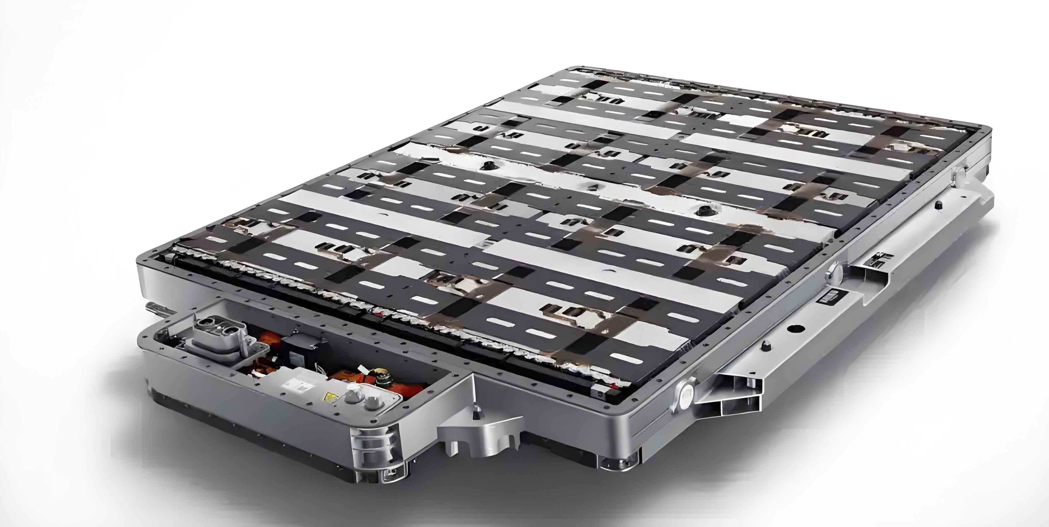
Modern electric vehicle battery packs are complex, sealed, and safety-critical assemblies designed for high energy density, structural integrity, thermal management, and protection.
- Structural Overview: The pack is housed within a robust enclosure, typically comprising:
- Lower Tray/Chassis: The primary structural member, bearing the weight of all internal components and often contributing to vehicle chassis stiffness. It features reinforced longitudinal and transverse beams. It usually houses two main zones:
- Main Compartment: Contains the battery modules and the thermal management system (cooling plates/heating elements).
- Auxiliary/Service Compartment: Houses the Battery Management System (BMS) controllers, the High Voltage Junction Box (HVJB) / Power Distribution Unit (PDU), fuses, contactors, and often the charging port interface.
- Upper Cover: Seals the pack. Often divided into:
- Large Cover: Seals the main module compartment.
- Small Cover/Access Panel: Seals the auxiliary/service compartment, allowing access for maintenance without exposing modules.
- Sealing: Critical for safety (preventing ingress of water, dust, and fumes) and thermal management. Sealing is achieved using specialized gaskets, sealants (e.g., silicone, butyl), and robust bolting, typically meeting high IP ratings like IP67 or IP68 (submersible). Seals must withstand high-pressure water jets and thermal cycling.
- Lower Tray/Chassis: The primary structural member, bearing the weight of all internal components and often contributing to vehicle chassis stiffness. It features reinforced longitudinal and transverse beams. It usually houses two main zones:
- Thermal Management System (TMS): Essential for maintaining optimal cell temperature (typically ~15°C to 35°C) during operation and charging/discharging. Common systems include:
- Liquid Cooling/Heating: Most prevalent in modern, high-performance electric vehicles. Cold plates integrated into the module structure circulate coolant (water-glycol mixture). Offers high heat transfer efficiency for both cooling and heating. Requires pumps, radiators, chillers (for active cooling), and PTC heaters.
- Air Cooling/Heating: Simpler and cheaper, using forced cabin or ambient air. Less efficient than liquid systems, limiting performance in extreme conditions or during fast charging. Still used in some lower-cost or lower-power electric vehicles.
- Phase Change Materials (PCMs)/Heat Pipes: Less common; used for passive thermal buffering or targeted heat spreading.
- Electrical Components:
- Battery Modules: The fundamental building blocks (discussed in detail next section).
- Busbars: Thick copper or aluminum bars connecting modules in series/parallel to achieve the pack’s total voltage and current capacity. Often incorporate sensors or fuses.
- High Voltage Junction Box (HVJB) / Power Distribution Unit (PDU): Contains the main contactors (relays) that connect/disconnect the battery pack from the vehicle’s high-voltage system, high-current fuses, pre-charge circuits, and often current sensors (shunts or Hall effect). It is the central hub for distributing high-voltage power to the inverter and other HV loads (e.g., DC-DC converter, PTC heater, charger).
- Wiring Harnesses: Extensive low-voltage wiring for BMS communication, sensor signals (voltage, temperature), and high-voltage cables connecting the pack to the inverter and charging port.
- Safety Devices: Includes:
- Manual Service Disconnect (MSD): A removable plug or fuse enabling safe isolation of the HV system for maintenance.
- Pyro Fuses: Explosively activated fuses designed to disconnect the battery extremely rapidly in the event of a severe short circuit or collision.
- Thermal Fuses/Fusible Links: Protect against localized overheating.
- Vent Valves/Pressure Relief Devices (PRDs): Safely release internal gases if pressure builds up dangerously due to cell thermal runaway, preventing catastrophic rupture.
4. Cell-to-Module-to-Pack Configuration
Understanding how individual cells are grouped is vital for comprehending pack voltage, capacity, and serviceability.
- Cell: The fundamental electrochemical unit (e.g., cylindrical like 18650/21700, prismatic, or pouch cell).
- Module: A physical and electrical assembly grouping multiple cells together, typically with a rigid frame, electrical interconnects, and often integrated voltage/temperature sensors. Modules are the smallest replaceable unit within a pack. Cells within a module are connected in Parallel (P), Series (S), or a combination (SP). The module configuration defines its voltage and capacity:
- Parallel Connection (P): Connects the positive terminals together and the negative terminals together. Increases Capacity (Ah) and Current Capability (A). The module voltage equals the voltage of a single cell.
C_module = n * C_cell(wheren= number of parallel cells). - Series Connection (S): Connects the positive terminal of one cell to the negative terminal of the next. Increases Voltage (V). The module capacity equals the capacity of a single cell.
V_module = m * V_cell(wherem= number of series cells). - Series-Parallel (SP): Combines groups of parallel-connected cells connected in series. Increases both Voltage and Capacity. Configuration is denoted as
xPyS:x= Number of cells connected in Parallel per group.y= Number of those parallel groups connected in Series.- Module Voltage:
V_module = y * V_cell - Module Capacity:
C_module = x * C_cell
- Parallel Connection (P): Connects the positive terminals together and the negative terminals together. Increases Capacity (Ah) and Current Capability (A). The module voltage equals the voltage of a single cell.
- Pack: The complete assembly installed in the electric vehicle, formed by connecting multiple modules in Series (S), Parallel (P), or Series-Parallel (SP) configuration. The pack configuration defines its total voltage and capacity:
- Pack Voltage:
V_pack = (Number of Series Modules) * V_moduleORV_pack = (Total Series Cells) * V_cell - Pack Capacity:
C_pack = (Number of Parallel Module Strings) * C_moduleORC_pack = (Total Parallel Cells) * C_cell
- Pack Voltage:
*Table 2: Example Configuration – Xiaopeng P7 Powertrain Battery Specifications*
| Parameter / Indicator | Long Range Version | Standard Range Version | Unit |
|---|---|---|---|
| Battery Pack | |||
| Model | TPLi0808-346 | TPLi0708-350 | – |
| Configuration (Cell Level) | 2P96S | 4P96S | – |
| Total Cells | 192 | 384 | – |
| Rated Capacity | 234 | 202 | Ah |
| Rated Energy | 80.87 | 70.78 | kWh |
| Rated Voltage | 345.6 | 350.4 | V |
| Charge Temp Range | -20 ~ 55 | -20 ~ 55 | °C |
| Discharge Temp Range | -30 ~ 55 | -30 ~ 55 | °C |
| Max Continuous Charge Current | 336 | 333 | A |
| Max Continuous Discharge Current | 234 | 202 | A |
| Protection Rating | IP68 | IP68 | – |
| Weight | 490 ± 14 | 450 ± 13 | kg |
| Module | |||
| Configuration (Cell Level) | 2P6S | 4P4S | – |
| Rated Capacity | 234 | 202 | Ah |
| Rated Voltage | 21.6 | 14.6 | V |
| Weight | 23.4 | 14.6 | kg |
| Cell | |||
| Type | NMC (Ternary) | NMC (Ternary) | – |
| Rated Voltage | 3.6 | 3.65 | V |
| Voltage Range | 2.85 ~ 4.2 | 2.5 ~ 4.2 | V |
| Rated Capacity | 117 | 50.5 | Ah |
Configuration Analysis (P7 Example):
- Long Range (2P96S):
- Cells: 192 total (2 parallel groups * 96 series groups).
- Module Config:
2P6Simplies each module has 12 cells (2 parallel * 6 series). Pack has 16 modules (192 cells / 12 cells per module = 16 modules). Modules connected in series:16S. - Pack Voltage:
96S * 3.6V = 345.6VOR16S * 21.6V = 345.6V. - Pack Capacity:
2P * 117Ah = 234Ah.
- Standard Range (4P96S):
- Cells: 384 total (4 parallel groups * 96 series groups).
- Module Config:
4P4Simplies each module has 16 cells (4 parallel * 4 series). Pack has 24 modules (384 cells / 16 cells per module = 24 modules). Modules connected in series:24S. - Pack Voltage:
96S * 3.65V ≈ 350.4VOR24S * 14.6V ≈ 350.4V. - Pack Capacity:
4P * 50.5Ah = 202Ah.
5. Battery Management System (BMS)
The BMS is the “brain” of the electric vehicle battery pack, essential for safe, efficient, and reliable operation. It constantly monitors and controls the pack.
- Core Functions:
- Cell Monitoring: Precisely measures the voltage of every individual cell or cell group within the pack. Critical for detecting weak cells and preventing overcharge/over-discharge.
- Temperature Monitoring: Measures temperatures at multiple critical points (cell surfaces, busbars, coolant in/out) using thermistors or thermocouples. Essential for thermal management and safety.
- Current Monitoring: Precisely measures pack current (in/out) using shunts or Hall effect sensors. Fundamental for SOC calculation, power limits, and energy throughput.
- State Estimation:
- State of Charge (SOC): Uses complex algorithms (e.g., Coulomb Counting combined with OCV lookup tables and Kalman Filters) to estimate the remaining usable capacity. Accuracy is paramount for driver range prediction.
- State of Health (SOH): Estimates the battery’s degradation level (capacity fade, resistance increase) relative to its new state, typically expressed as a percentage. Informs warranty and potential replacement needs.
- State of Power (SOP): Calculates the maximum allowable charge and discharge power the pack can safely deliver at the current moment, based on temperature, SOC, SOH, and cell voltage limits. Governs acceleration and regenerative braking capability.
- State of Function (SOF): An overarching term sometimes used for the pack’s ability to perform its required functions (starting, driving, charging) based on all other states and conditions.
- Cell Balancing: Actively (dissipating excess charge via resistors) or passively (shuttling charge between cells) corrects voltage imbalances between cells/modules caused by manufacturing variations or uneven aging. Balancing maximizes usable pack capacity and extends lifespan.
- Thermal Management Control: Interfaces with the Thermal Management System (TMS – coolant pumps, valves, heaters, chillers) to maintain the pack within its optimal temperature range based on sensor readings and operational demands.
- Safety Protection: Continuously checks for critical faults and takes immediate action:
- Overvoltage (individual cell or pack)
- Undervoltage (individual cell or pack)
- Overcurrent (charge/discharge)
- Safety Protection (Continued):
- Short Circuit (internal or external)
- Overtemperature (cells, electronics)
- Undertemperature
- Isolation Fault (Loss of HV insulation integrity)
- Communication faults within BMS or with Vehicle Controller
- Actions include opening contactors (disconnecting HV), derating power, illuminating warnings, and logging faults.
- Contactor Control: Directly controls the high-voltage contactors (relays) in the HVJB to connect or isolate the battery pack from the rest of the vehicle’s high-voltage system (e.g., during startup/shutdown, charging, fault conditions).
- Charging Control: Communicates with the onboard charger (OBC) or external DC fast charger to manage the charging process according to battery state (SOC, temp, SOH), defining maximum charge voltage, current, and duration. Implements charging protocols (CC/CV).
- Communication: Interfaces with other vehicle controllers via communication buses (CAN, LIN, Ethernet):
- Vehicle Control Unit (VCU): Reports key states (SOC, SOH, SOP, faults), receives torque/power requests, controls contactors.
- Power Electronics (Inverter, OBC, DC-DC): Coordinates power flow during driving and charging.
- Instrument Cluster/Infotainment: Provides driver information (range, state of charge, charging status, warnings).
- Telematics (Remote Monitoring): Transmits diagnostic and usage data.
- Data Logging: Records operational data, fault codes, and historical information for diagnostics, warranty analysis, and performance optimization.
- Hardware Architecture: The BMS is typically a distributed system:
- Battery Monitoring ICs (Slave Boards): Located directly on or near battery modules. Responsible for high-precision cell voltage and temperature measurement of a group of cells (e.g., 6-18 cells). Transmit data to the Master Controller.
- BMS Master Controller: The central processing unit. Receives data from all Slave Boards and other sensors (current, pack voltage, isolation). Executes all core algorithms (SOC, SOH, SOP, balancing, protection). Controls contactors and communicates with the vehicle network.
- High Voltage Junction Box (HVJB) Integration: Often houses the main contactors, fuses, current sensor, and sometimes the pre-charge circuit and isolation monitoring circuitry. The Master Controller directly controls components within the HVJB.
- Auxiliary Hardware: Includes wiring harnesses, connectors, isolation monitors, and potentially dedicated balancing boards.
Conclusion
The powertrain battery system is a masterpiece of modern engineering, integrating complex electrochemistry, advanced materials, sophisticated power electronics, and intricate control software. Its performance parameters – voltage, capacity, energy and power density, C-rate, internal resistance, and longevity – are intrinsically linked to the electric vehicle’s core capabilities: range, acceleration, charging speed, and overall durability. The choice of lithium-ion chemistry (NMC, NCA, LFP) involves critical trade-offs between energy density, cost, safety, and lifespan, shaping the vehicle’s target market and performance profile.
The physical architecture, from the robust, sealed enclosure to the meticulous arrangement of cells into modules and the pack, ensures mechanical integrity, thermal management, and safety compliance. The configuration logic (P, S, SP) dictates the fundamental electrical characteristics of voltage and capacity at every level. Ultimately, the Battery Management System acts as the indispensable guardian and optimizer, performing continuous monitoring, precise state estimation, active balancing, stringent safety protection, and seamless integration with the vehicle’s powertrain and charging systems. As electric vehicle technology advances relentlessly, innovations in cell chemistry (solid-state), pack design (Cell-to-Chassis – CTC), thermal management, and BMS algorithms will continue to push the boundaries of performance, safety, and affordability, solidifying the role of the battery as the definitive heart of the electric vehicle revolution.