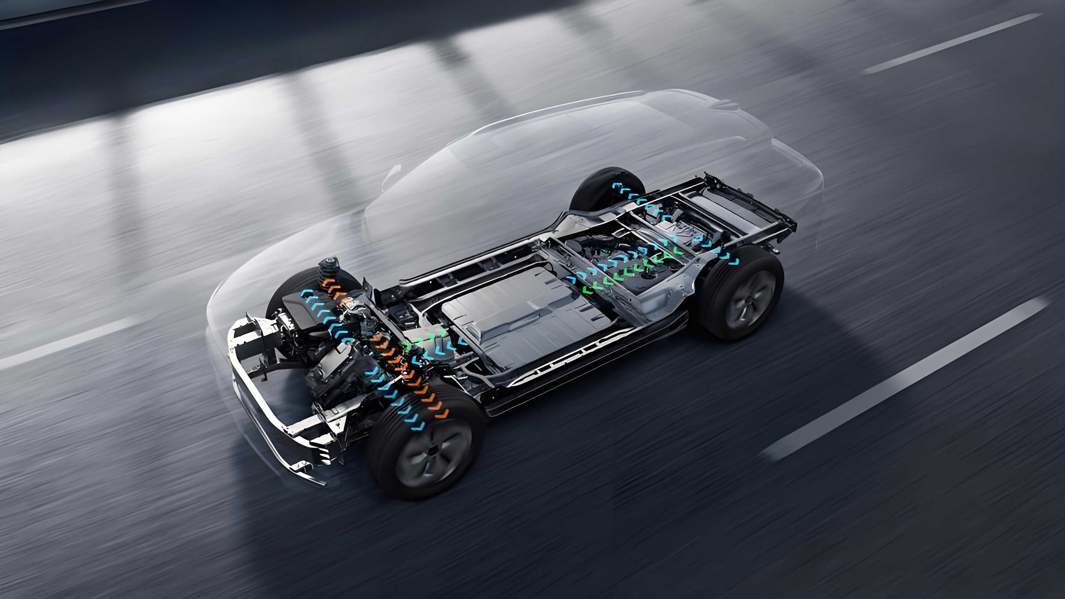
As a researcher specializing in electric vehicle thermal systems, I present a comprehensive analysis of a novel Variable Superheat Control Strategy (VSCS) for integrated thermal management systems (ITMS) in electric vehicles. This approach addresses critical limitations of conventional strategies, such as temperature fluctuations, energy inefficiency, and compressor reliability risks, which directly impact electric vehicle range and battery longevity.

1. Introduction
Electric vehicles face dual thermal challenges: high energy consumption from cabin HVAC systems and battery performance degradation at extreme temperatures. Conventional PTC heaters waste energy, reducing driving range by 5%–22% compared to heat pump systems. Integrated thermal management, combining cabin HVAC, battery cooling, and motor waste heat recovery, improves overall efficiency. However, strong coupling between subsystems causes significant temperature oscillations during dynamic operations (e.g., rapid battery heating during fast charging). Existing strategies fail to decouple these interactions, necessitating the VSCS framework developed in this study.
2. System Architecture and Mathematical Modeling
The ITMS uses R134a refrigerant and coolant loops (Figure 1). Key components include:
- Compressor: Displacement = 45 cm³/r, speed = 0–8,000 rpm.
- Heat Exchangers: Plate-type (water-cooled condenser/chiller) and microchannel evaporator.
- Control Valves: Two electronic expansion valves (EEVs) with diameters of 2.6 mm (cabin branch) and 1.8 mm (battery branch).
Mathematical Models:
- Compressor:m˙=ηvρsNVd,Δh=(hd,s−hs)/ηi,P=m˙Δhηmm˙=ηvρsNVd,Δh=(hd,s−hs)/ηi,P=m˙ηmΔhwhere m˙m˙ = refrigerant mass flow rate, ηv,ηi,ηmηv,ηi,ηm = volumetric/isentropic/mechanical efficiencies, ρsρs = suction density, NN = speed, VdVd = displacement.
- Heat Exchangers:Q=αS(Tr−Tw),Q=m˙(hin−hout)Q=αS(Tr−Tw),Q=m˙(hin−hout)where αα = heat transfer coefficient, SS = surface area.
- System COP:COP=Qevap+QcondPcompCOP=PcompQevap+Qcond
Table 1: Key Parameters of the Electric Vehicle Thermal Management System
| Component | Parameter | Value |
|---|---|---|
| Compressor | Displacement | 45 cm³/r |
| Speed Range | 0–8,000 rpm | |
| Water-Cooled Condenser | Plate Area | 21,718 mm² |
| Chiller | Refrigerant Passes | 35 |
| Microchannel Evaporator | Dimensions | 205 mm × 235 mm × 38 mm |
| EEV Cabin | Diameter | 2.6 mm |
| EEV Battery | Diameter | 1.8 mm |
3. Variable Superheat Control Strategy
3.1. Conventional Strategy Limitations
- Compressor controls cabin temperature.
- EEVs maintain fixed superheat (5°C).
- Battery EEV operates in on/off mode based on coolant temperature thresholds (e.g., opens fully >32°C).
Defects:- Cabin/battery coupling causes ±3.6°C cabin air temperature swings during battery heat surges.
- Evaporation pressure fluctuates between 0.4–0.75 MPa, risking compressor slugging.
3.2. VSCS Implementation
- Compressor: Regulates evaporation pressure (PevapPevap).
- EEVs: Independently control branch cooling capacity (Qcabin,QbatQcabin,Qbat).
- PID Controllers: Adjust compressor speed and EEV openings.
Control Logic:Pevap, target=f(Tcabin, target,Tbat, target,TambPevap, target=f(Tcabin, target,Tbat, target,TambEEVopen=PID(Tbranch, actual,Tbranch, targetEEVopen=PID(Tbranch, actual,Tbranch, target
Table 2: VSCS vs. Conventional Strategy Performance
| Metric | Conventional | VSCS (0.4 MPa) | Improvement |
|---|---|---|---|
| Cabin Air Temp Fluctuation | ±3.6°C | ±1.1°C | 69% reduction |
| Max Battery Coolant Temp | 42.2°C | 32.3°C | 9.9°C lower |
| Compressor Slugging Occurrence | Yes | No (at 0.4/0.5 MPa) | Eliminated |
4. Simulation Results and Analysis
Simulations under 40°C ambient:
- Battery Heat Profile: 1.5 kW (steady) → WLTC cycle (dynamic) → 9 kW (extreme).
- Cabin Target: 28°C air outlet.
4.1. Temperature Stability
- VSCS (0.4 MPa): Cabin air fluctuation ≤1.1°C (vs. 3.6°C conventional) during 9 kW battery load.
- Battery Coolant: Peaked at 32.3°C (VSCS) vs. 42.2°C (conventional).
4.2. Energy Consumption
- Lower Pevap, targetPevap, target increases compressor work due to reduced suction density:Pcomp∝1ρs⋅PcondPevapPcomp∝ρs1⋅PevapPcondTable 3: Energy Penalty at Low Evaporation PressuresPevap, targetPevap, targetAvg. Compressor Power (kW)COP Relative Change0.6 MPa2.8Baseline0.5 MPa3.4-18%0.4 MPa4.1-31%
4.3. Refrigerant Dynamics
- Superheat Control: VSCS maintains >0°C superheat (Figure 11), preventing slugging.
- EEV Responsiveness: Battery EEV opening adjusts ±80% during load transients, decoupling cabin impacts.
5. Target Evaporation Pressure Optimization
Optimal Pevap, targetPevap, target depends on operational modes:Pevap, target={0.6 MPaSteady State (battery heat < 2 kW)0.5 MPaModerate Transients0.4 MPaExtreme Loads (battery heat > 5 kW)Pevap, target=⎩⎨⎧0.6 MPa0.5 MPa0.4 MPaSteady State (battery heat < 2 kW)Moderate TransientsExtreme Loads (battery heat > 5 kW)
Rationale: Higher PevapPevap saves energy during mild conditions; lower PevapPevap enhances stability and cooling during transients.
6. Conclusion
The VSCS significantly enhances electric vehicle thermal management:
- Decouples cabin/battery control, reducing cabin temperature fluctuations by 69%.
- Lowers peak battery coolant temperature by 9.9°C in extreme loads.
- Prevents compressor slugging via superheat regulation.
- Adaptive Pevap, targetPevap, target selection balances efficiency and stability.
Future work will extend VSCS to heating-dominated scenarios and multi-zone control. This strategy establishes a foundation for precision thermal management in next-generation electric vehicles.
