
As a researcher specializing in vehicle dynamics and control, I present a comprehensive study on enhancing ride comfort and handling stability for electric vehicles (EVs), specifically focusing on in-wheel motor-driven configurations. The integration of hub motors introduces significant challenges, including increased unsprung mass and electromagnetic disturbances that exacerbate vertical vibrations. This work details the development of a robust semi-active suspension system using magnetorheological (MR) dampers, validated through rigorous modeling, simulation, and hardware-in-loop experimentation.
1. Introduction
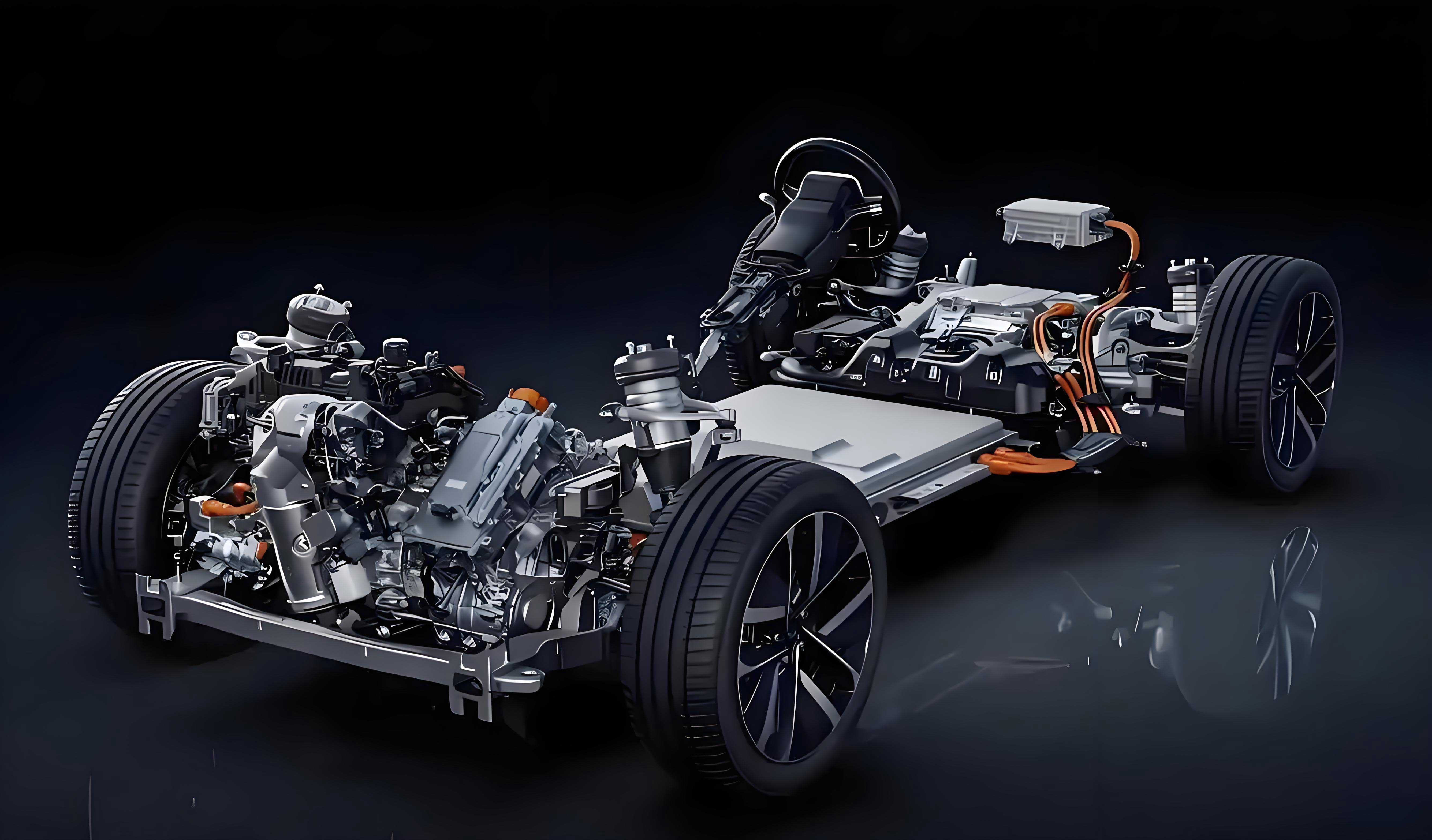
Electric vehicles with in-wheel motors offer advantages like compact design and high efficiency. However, the added unsprung mass and unbalanced electromagnetic forces induce severe vertical vibrations, compromising ride comfort. Traditional solutions face limitations:
- Lightweight design is constrained by material strength and cost.
- Reconfiguring motor mounts increases complexity and reduces reliability.
- Semi-active control using MR dampers emerges as the optimal solution, providing rapid response, low energy consumption, and continuous force adjustability.
This study addresses:
(i) High-fidelity modeling of MR dampers,
(ii) Characterization of electromagnetic disturbances from hub motors,
(iii) Design of an H∞ robust controller accommodating parameter uncertainties,
(iv) Experimental validation on a custom electric vehicle suspension test rig.
2. Magnetorheological Damper Modeling
2.1. Experimental Characterization
MR damper dynamics were evaluated under harmonic excitation (amplitude: 5 mm; frequency: 0.5 Hz/1 Hz; current: 0–2.5 A). Key observations:
- Damping force increases with input current.
- Force-displacement curves approximate rectangular hysteresis loops.
- Force-velocity profiles exhibit nonlinear hyperbolic characteristics with pronounced hysteresis.
Table 1: Identified Parameters for Modified Hyperbolic Tangent Model
| Current (A) | a1a1 | a2a2 | a3a3 | kk | f0f0 |
|---|---|---|---|---|---|
| 0.0 | 149.14 | 0.22 | 0.39 | 1.90 | 44.35 |
| 0.5 | 256.87 | 0.31 | 0.34 | 2.07 | 45.19 |
| 1.0 | 434.21 | 0.36 | 0.36 | 3.06 | 34.52 |
| 1.5 | 580.35 | 0.37 | 0.38 | 4.13 | 53.99 |
| 2.0 | 713.77 | 0.36 | 0.42 | 5.35 | 47.19 |
| 2.5 | 820.67 | 0.31 | 0.44 | 6.36 | 34.44 |
2.2. Modified Hyperbolic Tangent Model
The improved model captures nonlinear hysteresis:F=(b1I+c1)tanh(a2(x˙+kx))+(b2I+c2)(x˙+kx)+f0F=(b1I+c1)tanh(a2(x˙+kx))+(b2I+c2)(x˙+kx)+f0
where b1=278.7b1=278.7, c1=144c1=144, a2=0.32a2=0.32, k=0.38k=0.38, b2=1.89b2=1.89, c2=1.45c2=1.45, f0=44f0=44. Parameter a1a1 and a3a3 vary linearly with current:a1=278.7I+144,a3=1.89I+1.45.a1=278.7I+144,a3=1.89I+1.45.
Model accuracy was verified (RMS error < 0.36%).
3. EV Semi-Active Suspension System
3.1. Dynamics with Hub Motor Disturbances
A quarter-car model integrates MR damper dynamics and electromagnetic forces:msz¨s+ks(zs−zu)=Fdmsz¨s+ks(zs−zu)=Fd(mu+mw)z¨u+ks(zu−zs)+kt(zu−zr)=Fm−Fd(mu+mw)z¨u+ks(zu−zs)+kt(zu−zr)=Fm−Fd
where FdFd = MR damper force, FmFm = electromagnetic force, msms = sprung mass, mumu = unsprung mass, mwmw = hub motor mass, ksks = suspension stiffness, ktkt = tire stiffness.
Table 2: Vehicle Parameters
| Parameter | Value |
|---|---|
| Sprung mass (msms, kg) | 450 |
| Wheel mass (mumu, kg) | 21 |
| Motor mass (mwmw, kg) | 51.9 |
| Suspension stiffness (ksks, N/m) | 35,714 |
| Tire stiffness (ktkt, N/m) | 200,330 |
3.2. Electromagnetic Force Analysis
Finite element analysis (ANSYS Maxwell) characterized electromagnetic forces under rotor eccentricity:
- Static eccentricity: Forces shift from equilibrium position.
- Dynamic eccentricity: Forces oscillate harmonically at 7.2 Hz (wheel speed: 60 km/h).
- Dominant frequency (7.2 Hz) aligns with human sensitivity (4–8 Hz per ISO 2631), critically impacting ride comfort.
4. Robust H∞ Control Design
4.1. State-Space Formulation
Uncertainties in sprung mass (ms=m^s(1+dmδ(t))ms=m^s(1+dmδ(t))) are incorporated:x˙=(A+ΔA)x+(Bu+ΔBu)u+Bwwx˙=(A+ΔA)x+(Bu+ΔBu)u+Bwwz=(C1+ΔC1)x+(Du1+ΔDu1)uz=(C1+ΔC1)x+(Du1+ΔDu1)u
where x=[zs−zu,z˙s,zu−zr,z˙u]Tx=[zs−zu,z˙s,zu−zr,z˙u]T, w=[zr,Fm]Tw=[zr,Fm]T, u=Fdu=Fd.
4.2. Control Synthesis
A state-feedback controller u=Kxu=Kx is designed via Linear Matrix Inequalities (LMIs) to minimize the H∞ norm from ww to performance output zz:[Θ1∗∗H1TP+H2TCidH2TH2−λ∗BwTP0−γ2I]<0Θ1H1TP+H2TCidBwTP∗H2TH2−λ0∗∗−γ2I<0
where Θ1=AdTP+PAd+CidTCid+(E1+E2K)Tλ(E1+E2K)Θ1=AdTP+PAd+CidTCid+(E1+E2K)Tλ(E1+E2K), Ad=A+BuKAd=A+BuK.
5. Performance Validation
5.1. Simulation Results
5.1.1. Random Road (B-Class, 60 km/h)
Table 3: RMS Responses (Random Road)
| Metric | Passive | Skyhook | H∞ |
|---|---|---|---|
| Body acceleration (m/s²) | 0.586 | 0.467 | 0.425 |
| Suspension travel (×10⁻² m) | 7.358 | 5.385 | 4.069 |
| Tire load (N) | 532.3 | 489.7 | 429.6 |
H∞ control reduces body acceleration RMS by 27.4% vs. passive and 9.0% vs. skyhook.
5.1.2. Impact Road (Convex Block)
H∞ control achieves:
- 41.2% lower peak body acceleration vs. passive.
- 22.3% faster settling time vs. skyhook.
5.1.3. Robustness to Mass Variation (±20%)
Table 4: Body Acceleration RMS vs. Sprung Mass
| msms (kg) | Passive (m/s²) | Skyhook (m/s²) | H∞ (m/s²) |
|---|---|---|---|
| 350 | 0.672 | 0.537 | 0.471 |
| 450 | 0.586 | 0.467 | 0.425 |
| 550 | 0.523 | 0.418 | 0.381 |
H∞ maintains superior performance despite mass uncertainties.
5.2. Experimental Validation
A 1/4 vehicle test rig with a hub motor and MR damper was developed. Harmonic excitations (5–10 Hz) were applied:
Table 5: Experimental Reduction in Body Acceleration RMS
| Frequency (Hz) | Reduction by H∞ vs. Passive |
|---|---|
| 5 | 24.49% |
| 7 | 15.43% |
| 10 | 23.78% |
6. Conclusion
This study establishes a holistic framework for enhancing the dynamics of electric vehicles with in-wheel motors:
- MR Damper Modeling: The modified hyperbolic tangent model accurately captures hysteresis (error < 0.36%), enabling precise semi-active force control.
- Electromagnetic Disturbances: Dynamic rotor eccentricity induces critical vibrations at 7.2 Hz, necessitating targeted control.
- Robust H∞ Control: Accommodates ±20% sprung mass variations, outperforming skyhook by 9–18% in acceleration suppression.
- Experimental Efficacy: Real-time tests confirm 15–25% improvement in ride comfort across 5–10 Hz disturbances.
The proposed system significantly advances the viability of high-comfort, high-efficiency electric vehicles, particularly those employing in-wheel motor architectures. Future work will extend this framework to full-vehicle multi-objective optimization.
Appendix: Key Formulas
- MR Damper Force:F=(278.7I+144)tanh(0.32(x˙+0.38x))+(1.89I+1.45)(x˙+0.38x)+44F=(278.7I+144)tanh(0.32(x˙+0.38x))+(1.89I+1.45)(x˙+0.38x)+44
- Closed-Loop H∞ Stability:[Θ1H1TP+H2TCidBwTP∗H2TH2−λ0∗∗−γ2I]<0Θ1∗∗H1TP+H2TCidH2TH2−λ∗BwTP0−γ2I<0
- Road Excitation (Random):q˙=−0.111[vq(t)+40Gq(n0)v w0(t)]q˙=−0.111[vq(t)+40Gq(n0)vw0(t)]