
As a researcher deeply involved in the field of new energy vehicles, I am constantly exploring methodologies to streamline and enhance the design process. The hybrid electric vehicle (HEV), which synergistically combines the advantages of the traditional internal combustion engine (ICE) and the pure electric motor, represents the most promising transitional product towards full electrification. Its development necessitates sophisticated matching and simulation of the powertrain system. While numerous simulation tools exist, their application scope is often narrow. Therefore, this article details the comprehensive development of a versatile simulation platform based on MATLAB/GUI, capable of evaluating the dynamic performance of not only hybrid electric vehicles but also, by extension, pure electric vehicles (EVs) and traditional ICE vehicles in isolation.
The core of any credible simulation lies in its mathematical foundation. For this platform, the modeling process is segmented into three interconnected components: the drive motor, the transmission system, and the vehicle dynamics. The parameters of the drive motor are meticulously matched to meet stringent vehicle dynamic targets, including maximum speed, acceleration capability, and gradeability. The required power for sustaining maximum speed on a level road is derived from the road load equation:
$$P_1 = \frac{u_{max}}{3600 \eta_t} \left( mgf + \frac{C_D A u_{max}^2}{21.15} \right)$$
where \( P_1 \) is the power required at maximum speed \( u_{max} \), \( m \) is the vehicle mass, \( g \) is gravitational acceleration, \( f \) is the rolling resistance coefficient, \( C_D \) is the drag coefficient, \( A \) is the frontal area, and \( \eta_t \) is the drivetrain efficiency. Similarly, the power needed for maximum gradeability \( \alpha_{max} \) at speed \( u_p \) is:
$$P_2 = \frac{u_p}{3600 \eta_t} \left( mgf \cos \alpha_{max} + mg \sin \alpha_{max} + \frac{C_D A u_p^2}{21.15} \right)$$
The acceleration power demand is given by:
$$P_3 = \frac{u}{3600 \eta_t} \left( mgf + \frac{C_D A u^2}{21.15} + \delta m \frac{du}{dt} \right)$$
Here, \( \delta \) is the rotational mass factor and \( du/dt \) is the acceleration. The motor’s rated power \( P_e \) must exceed \( P_1 \), while its peak power \( P_{emax} \) must be greater than the maximum of \( P_1 \), \( P_2 \), and \( P_3 \). The motor’s speed and torque specifications are consequently determined:
$$n_{emax} \ge \frac{0.377 u_{max} i_0 i_1}{r}, \quad T_e = 9550 \frac{P_e}{n_e}, \quad T_{emax} \ge \frac{r (mgf \cos \alpha_{max} + mg \sin \alpha_{max})}{\eta_t i_0 i_1}$$
To balance performance, efficiency, and structural complexity, a 2-speed transmission is adopted for the hybrid electric vehicle. The gear ratios are calculated to satisfy both traction and speed requirements while ensuring drivability. The first gear ratio \( i_1 \) must provide enough torque for maximum gradeability without causing wheel slip, bounded by the tire-road adhesion limit:
$$\frac{r \phi m g b/L}{\eta_t T_{emax} i_0} \le i_1 \le \frac{r}{\eta_t T_{emax} i_0} \left( mgf \cos \alpha_{max} + mg \sin \alpha_{max} + \frac{C_D A u_p^2}{21.15} \right)$$
The second gear ratio \( i_2 \) must enable the maximum vehicle speed while maintaining sufficient driving force at high speed:
$$\frac{r}{\eta_t T_{umax} i_0} \left( mgf + \frac{C_D A u_{max}^2}{21.15} \right) \le i_2 \le \frac{0.377 n_{emax} r}{u_{max} i_0}$$
Furthermore, for smooth shifting, the torque in the second gear at the motor’s base speed should be greater than the torque in the first gear at the motor’s maximum speed, leading to the constraint \( i_2 / i_1 \le n_{emax} / n_e \). The overall vehicle dynamics model integrates these components. The driving force \( F_t \) at the wheels is:
$$F_t = \frac{T i_t \eta_t}{r}$$
where \( T \) is the output torque from the power source (motor, engine, or combined) and \( i_t \) is the total transmission ratio. The road load comprises rolling resistance \( F_f \) and aerodynamic drag \( F_w \):
$$F_f = mgf, \quad F_w = \frac{C_D A u^2}{21.15}$$
The dynamic factor \( D \), a key metric for performance evaluation, is defined as:
$$D = \frac{F_t – F_w}{mg} = f \cos \alpha + \sin \alpha + \frac{\delta}{g} \frac{du}{dt}$$
From this, the maximum gradability \( i \) (when \( du/dt = 0 \)) and the maximum acceleration \( a_{max} \) (when \( \alpha = 0 \)) can be derived:
$$i = \tan \left( \arcsin \frac{D-f}{\sqrt{1+(D-f)^2}} \right), \quad a_{max} = \frac{g}{\delta}(D – f)$$
For the hybrid electric vehicle operating in combined mode, a torque-coupling model is employed. If the engine outputs torque \( T_1 \) at speed \( \omega_1 \) and the motor outputs torque \( T_2 \) at speed \( \omega_2 \), the coupled output torque \( T_3 \) and speed \( \omega_3 \) are governed by the planetary gear set ratios \( S_1 \) and \( S_2 \):
$$T_3 \omega_3 = T_1 \omega_1 + T_2 \omega_2, \quad T_3 = S_1 T_1 + S_2 T_2, \quad \omega_3 = \omega_1 / S_1 = \omega_2 / S_2$$
With the mathematical models established, the next phase involves building the interactive simulation software using MATLAB’s Graphical User Interface (GUI) module. This platform is designed with a logical flow, beginning with a start interface, progressing to a mode selection menu, and culminating in the dedicated simulation windows for Pure Electric Mode, Engine-Only Mode, and Hybrid Electric Vehicle Mode. The visual design prioritizes clarity: the left panel of each main interface hosts input fields for vehicle parameters, while the right panel displays graphical outputs such as the driving force-resistance balance chart, acceleration curve, and gradeability curve, alongside numerical results for top speed, maximum grade, and 0-100 km/h acceleration time.
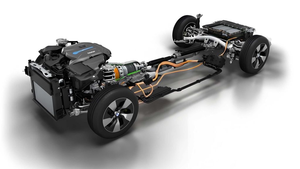
The figure above conceptually illustrates the integration of key components in a hybrid electric vehicle, which forms the basis for the simulation models. The software’s architecture is depicted in the following program flowchart, which outlines the user’s navigation path and the underlying computational logic for each operating mode of the hybrid electric vehicle.
Program Workflow:
- Start: Launch the application.
- Mode Selection: User chooses between Pure Electric, Engine-Only, or Hybrid Electric Vehicle Mode.
- Parameter Input: In the selected mode’s interface, the user inputs all necessary parameters (e.g., motor power, engine map, gear ratios, vehicle mass, drag coefficient).
- Calculation & Simulation: The software executes the corresponding mathematical models based on the selected mode.
- Pure Electric Mode: Uses the motor and EV dynamics model.
- Engine-Only Mode: Uses the engine map and vehicle dynamics model.
- Hybrid Electric Vehicle Mode: Uses the torque-coupling model combining both power sources.
- Result Output: The software generates and displays performance curves and key numerical metrics.
- Iteration: The user can modify inputs and recalculate to observe new results.
The callback functions for each GUI control element (buttons, input fields) are programmed to execute these steps. For instance, the ‘Calculate’ button’s callback fetches the input values, calls the relevant model functions, and plots the results. After completing the code, the application is compiled into a standalone software package using MATLAB’s Application Compiler tool (via the `deploytool` command).
To validate the platform’s utility, simulations were run for a sample vehicle in all three modes. The key parameters used for this demonstration are summarized in the table below. This consistent set of vehicle parameters allows for a direct comparison of performance across the different powertrain configurations of the hybrid electric vehicle and its constituent modes.
| Parameter | Symbol | Value | Unit |
|---|---|---|---|
| Vehicle Mass | \( m \) | 1500 | kg |
| Drag Coefficient | \( C_D \) | 0.30 | – |
| Frontal Area | \( A \) | 2.2 | m² |
| Rolling Resistance Coeff. | \( f \) | 0.015 | – |
| Wheel Radius | \( r \) | 0.32 | m |
| Final Drive Ratio | \( i_0 \) | 4.1 | – |
| 1st Gear Ratio | \( i_1 \) | 3.5 | – |
| 2nd Gear Ratio | \( i_2 \) | 1.8 | – |
| Drivetrain Efficiency | \( \eta_t \) | 0.92 | – |
| Motor Rated Power | \( P_e \) | 70 | kW |
| Motor Peak Power | \( P_{emax} \) | 120 | kW |
| Motor Base Speed | \( n_e \) | 3000 | rpm |
| Motor Max Speed | \( n_{emax} \) | 8000 | rpm |
In Pure Electric Mode, the simulation yielded a top speed of 180.87 km/h, a maximum gradeability of 21.08%, and a 0-100 km/h acceleration time of 7.14 seconds. The Engine-Only Mode, using a predefined torque-speed map for a midsize gasoline engine, resulted in a higher top speed of 198.8 km/h but a lower gradeability of 15.60% and a slower acceleration time of 12.16 seconds. The true advantage of the hybrid electric vehicle configuration became evident in the Hybrid Mode simulation. Utilizing torque coupling, the combined powertrain achieved a top speed comparable to the engine mode at 198 km/h, but dramatically improved the gradeability to 44.66% and reduced the 0-100 km/h time to just 6.09 seconds. These results are consolidated for comparison in the table below.
| Performance Metric | Pure Electric Mode | Engine-Only Mode | Hybrid Electric Vehicle Mode |
|---|---|---|---|
| Maximum Speed (km/h) | 180.87 | 198.80 | 198.00 |
| Maximum Grade (%) | 21.08 | 15.60 | 44.66 |
| 0-100 km/h Time (s) | 7.14 | 12.16 | 6.09 |
The analysis clearly demonstrates the performance synthesis of a hybrid electric vehicle. While the hybrid electric vehicle’s top speed is largely dictated by the engine’s high-speed power, its low-speed torque and acceleration are significantly enhanced by the electric motor’s instantaneous torque delivery. The torque-coupling mechanism in this hybrid electric vehicle model allows for additive torque at common output speeds, explaining the superior gradeability and acceleration compared to either power source operating alone. This validates the core premise of the hybrid electric vehicle: combining the strengths of both systems.
In conclusion, this article has presented a detailed methodology for developing a comprehensive powertrain dynamic performance simulation platform. The process encompassed the derivation of fundamental mathematical models for component matching and vehicle dynamics, followed by the systematic design and programming of an intuitive GUI-based software using MATLAB. The resulting platform successfully simulates and contrasts the dynamic characteristics of a vehicle operating in Pure Electric, Engine-Only, and integrated Hybrid Electric Vehicle modes. Its primary strength lies in its extended applicability; by virtue of the hybrid electric vehicle’s dual-power-source architecture, the same tool can be used effectively for the dedicated analysis of traditional internal combustion engine vehicles and pure electric vehicles. This provides automotive engineers and researchers with a unified, flexible, and user-friendly environment for initial powertrain matching, performance prediction, and comparative studies, thereby accelerating the design and evaluation cycle for the next generation of hybrid electric vehicles and other vehicle types.