
As a technician specializing in hybrid electric vehicle systems, I recently encountered a case involving a 2024 model year Wuling Xingguang S hybrid electric vehicle. The customer reported that while the vehicle could achieve “READY” mode, drive normally, and perform DC fast charging without issues, it failed to charge via AC slow charging. This complaint highlighted a specific fault in the charging infrastructure of this hybrid electric vehicle, which integrates both internal combustion and electric powertrains. The vehicle had accumulated approximately 11,000 kilometers, making it relatively new, and thus the fault pointed towards either a component failure or an assembly issue. In this detailed account, I will walk through the diagnostic process, leveraging data analysis, systematic checks, and theoretical principles to resolve the issue. The emphasis will be on understanding the charging system in a hybrid electric vehicle, as these systems are critical for maintaining battery health and overall vehicle efficiency.
Upon receiving the hybrid electric vehicle, I first verified the fault. The dashboard indicated that the charging gun was connected, but no AC slow charging initiation occurred, confirming the customer’s complaint. This initial step is crucial in any diagnostic routine for a hybrid electric vehicle, as it ensures the problem is reproducible and not a transient glitch. Next, I connected a professional fault diagnostic scanner to the vehicle’s network. Scanning for fault codes across all control units yielded no relevant diagnostic trouble codes (DTCs). This absence of codes is common in some electrical or intermittent faults in a hybrid electric vehicle, where the system may not always log a code for every anomaly. Therefore, I proceeded to examine live data streams, specifically focusing on the onboard charger (OBC) module parameters.
The data stream from the charger revealed several key parameters. To systematically analyze these, I have summarized the observed values and their implications in the table below. The data highlighted anomalies in voltage and current readings, which are central to the charging function of a hybrid electric vehicle.
| Data Parameter | Observed Value | Normal Expected Value | Status |
|---|---|---|---|
| Charger Unit Temperature | 32°C | 20-50°C | Normal |
| Thermistor 1 Temperature | 31°C | Ambient ±10°C | Normal |
| Thermistor 2 Temperature | 33°C | Ambient ±10°C | Normal |
| Charging Connection Signal Resistance | 1.2 kΩ | ~1.0-1.5 kΩ | Normal |
| Charging Pilot Duty Cycle | 15% | 10-20% | Normal |
| Charger Input Voltage (AC) | 0.5 V | 230 V AC | Abnormal |
| Charger Input Current (AC) | 0.0 A | Variable, >0 A | Abnormal |
| Charger HV Output Voltage (DC) | 0.03 V | ~400 V DC | Abnormal |
| Charger HV Output Current (DC) | 0.0 A | Variable, >0 A | Abnormal |
The abnormal data for charger high-voltage (HV) output voltage, measured at nearly 0 V DC, was identified as the primary factor leading to the other irregularities. In a hybrid electric vehicle, the onboard charger converts AC grid power to DC high-voltage for battery charging. The output voltage should closely match the battery pack’s voltage, typically around 400 V DC in this class of hybrid electric vehicle. The near-zero reading indicated a breakdown in this conversion or delivery path. To understand this, we can refer to the basic power conversion relationship in an AC-DC charger:
$$ P_{out} = V_{out} \times I_{out} = \eta \times P_{in} $$
where \( P_{out} \) is the DC output power, \( V_{out} \) is the DC output voltage, \( I_{out} \) is the DC output current, \( \eta \) is the charger efficiency, and \( P_{in} \) is the AC input power. With \( V_{out} \approx 0 \), the output power is zero, regardless of input conditions, explaining the charging failure.
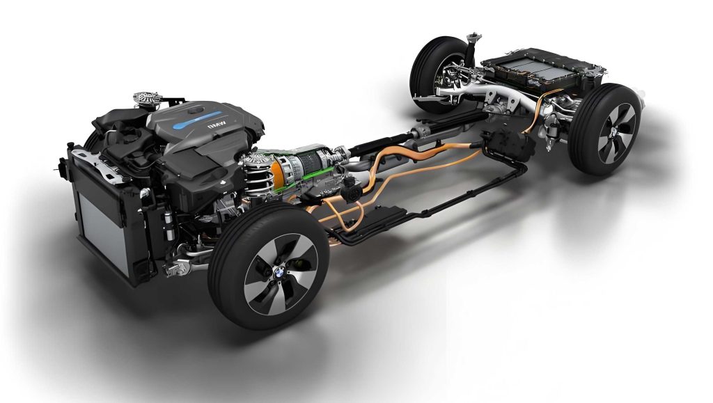
To diagnose further, I reviewed the high-voltage architecture of this hybrid electric vehicle. The framework integrates key components like the traction battery, motor controller, DC-DC converter, and onboard charger. A simplified representation of the high-voltage system in a typical hybrid electric vehicle is shown below, highlighting the paths for charging and propulsion.
| High-Voltage Component | Primary Function | Connection in Charging Path |
|---|---|---|
| Traction Battery Pack | Stores electrical energy | Receives DC from charger |
| Onboard Charger (OBC) | Converts AC to DC for charging | Outputs to battery via fuse |
| DC-DC Converter | Steps down HV to LV for auxiliaries | Often integrated with OBC |
| Motor Controller | Drives electric motor | Separate from charging path |
| High-Voltage Fuses | Protects circuits from overcurrent | In series between battery and OBC |
Given that the hybrid electric vehicle could achieve “READY” mode and drive, the main traction battery contactors (positive and negative relays) were functioning correctly, and the motor controller’s high-voltage circuit was intact. This narrowed the fault to the specific AC slow charging pathway. Based on the high-voltage framework and data analysis, I compiled a list of potential root causes for the AC charging failure in this hybrid electric vehicle. The list is prioritized by likelihood and ease of access, a common practice in troubleshooting complex systems like a hybrid electric vehicle.
| Potential Cause | Description | Diagnostic Priority |
|---|---|---|
| Charger Fuse Blown in Battery Pack | Fuse protecting the charger circuit opens due to overcurrent or short. | High (based on voltage absence) |
| Poor Contact at Charger Connectors | Corrosion, burn-out, or looseness at AC or DC connectors. | Medium (visual inspection easy) |
| Fault in High-Voltage Wiring | Damage, break, or short in cables between battery and charger. | Medium (requires physical check) |
| Onboard Charger Unit Failure | Internal fault in AC-DC conversion circuitry or control logic. | Medium to High (needs measurement) |
| Cooling System Failure for Charger | Overheating due to coolant leak or pump failure, leading to thermal shutdown or damage. | Low initially, but important |
Following the principle of starting with the most accessible checks, I first inspected the physical connectors and wiring. After performing a safe high-voltage shutdown procedure—disconnecting the low-voltage battery negative terminal and verifying isolation—I removed trunk linings to access the onboard charger. The slow charging connector on the charger side showed no signs of water ingress, burns, or corrosion. Similarly, upon lifting the hybrid electric vehicle, the connector on the traction battery side was also clean and secure. A visual inspection along the underbody high-voltage cable routing revealed no apparent damage, abrasion, or disconnection. This eliminated simple connection issues as the cause.
Next, to verify high-voltage presence, I temporarily shorted the high-voltage interlock loop (a safety circuit) to allow system activation without all connectors mated—a procedure done with extreme caution and proper personal protective equipment. After reconnecting the low-voltage battery, I powered the hybrid electric vehicle to “READY” state. Using a certified high-voltage multimeter, I measured the voltage at the charger’s DC output terminals (where the slow charge high-voltage cable connects). The reading was 0.03 V DC, as noted earlier, instead of the expected battery voltage. This confirmed that high-voltage was not reaching the charger output point. According to Ohm’s law, the current in a circuit is determined by voltage and resistance:
$$ I = \frac{V}{R} $$
If \( V \) is near zero, \( I \) will be zero, explaining the lack of charging current. The near-zero voltage could result from an open circuit (like a blown fuse) or a short circuit downstream pulling the voltage down. To isolate this, the next step was to examine the traction battery pack internals, specifically the charger fuse.
After again ensuring full high-voltage safety de-energization, I removed the traction battery pack from the hybrid electric vehicle. Inside the battery enclosure, I located the dedicated fuse for the charger circuit. A fuse is a protective device that melts when current exceeds its rating, defined by the integral of current over time (I²t). Using a multimeter in resistance mode, I measured across the fuse terminals. The resistance was infinite (open circuit), indicating a blown fuse. The normal resistance of a good fuse should be less than 1 Ω, ideally near 0 Ω. This finding was critical but not conclusive; a fuse blow is always a symptom of an underlying fault, such as an overload or short circuit. Simply replacing it risked immediate re-blowing or worse damage.
To find the root cause, I performed insulation resistance tests on the circuits downstream of the fuse. This involved measuring resistance between the high-voltage positive output of the fuse and the high-voltage negative bus, as well as on the cables and the charger itself. The key measurement was at the onboard charger unit’s high-voltage input terminals. Disconnecting the charger from the wiring, I measured the resistance between its positive and negative input terminals. The multimeter showed 0 Ω, indicating a direct short circuit inside the charger unit. This explained the fuse blow: a short circuit causes extremely high current, described by:
$$ I_{fault} = \frac{V_{source}}{R_{short}} $$
where \( R_{short} \) approaches zero, leading to \( I_{fault} \) approaching infinity, which exceeds the fuse rating almost instantaneously. In a hybrid electric vehicle, such a short in the charger could stem from component failure, often due to thermal stress. This led me to inspect the charger’s cooling system. The onboard charger in this hybrid electric vehicle is liquid-cooled to manage heat generated during high-power conversion. Upon close examination, I found coolant residue around the charger unit and on the carpeting beneath it in the trunk area. The cooling pipe接头 (joint) connected to the charger was loose, causing a slow coolant leak. This leak reduced the cooling efficiency, leading to charger overheating.
Thermal management is vital in a hybrid electric vehicle’s power electronics. The charger’s efficiency \( \eta \) is temperature-dependent; excessive temperature can degrade components, increase leakage currents, and ultimately cause dielectric breakdown or semiconductor failure, resulting in a short. The heat generation in the charger can be modeled as:
$$ Q_{generated} = P_{loss} = P_{in} – P_{out} = (1 – \eta) \times P_{in} $$
Without adequate cooling, the temperature rise \( \Delta T \) over time \( t \) is given by:
$$ \Delta T = \frac{Q_{generated}}{C_{th}} \times t $$
where \( C_{th} \) is the thermal capacity of the system. A coolant leak reduces the effective \( C_{th} \), causing \( \Delta T \) to increase rapidly, leading to thermal runaway and failure. In this case, the sustained overheating caused internal insulation breakdown, creating a short between the high-voltage positive and negative rails within the charger.
With the root cause identified—a loose cooling pipe joint leading to coolant leak, insufficient cooling, charger overheating, internal short circuit, and subsequent fuse blow—the repair steps were clear. I replaced the blown charger fuse with a new one of identical rating, replaced the entire onboard charger unit (as internal damage was irreversible), and replaced the faulty cooling pipe joint with a properly secured, OEM-specified connector. After reassembly and refilling the cooling system with the correct hybrid electric vehicle coolant, I performed a functional test. The hybrid electric vehicle now accepted AC slow charging normally, with the data stream showing proper voltages and currents. A subsequent drive cycle confirmed that all other functions, including DC fast charging and propulsion, remained intact.
This case underscores several important lessons for maintaining a hybrid electric vehicle. First, the cooling system is not just for the engine; it is critical for battery and power electronics health. Regular inspections of coolant lines, levels, and connections can prevent such failures. Second, diagnostic approaches should combine data analysis with understanding of system architecture. The use of data streams and resistance measurements, guided by electrical principles, was key here. Third, fuses are sacrificial protectors; always investigate why they blow before replacement. Finally, the integration of systems in a hybrid electric vehicle means that a fault in one area (cooling) can manifest in another (charging), requiring a holistic view.
To generalize, the charging system in a hybrid electric vehicle involves multiple safety and control layers. The communication between the charger, battery management system (BMS), and vehicle control unit (VCU) ensures safe operation. The AC charging process includes a pilot signal for capacity negotiation and proximity detection. A fault in any part of this chain can disable charging. Below is a summary of common failure modes in hybrid electric vehicle AC charging systems, based on this and similar cases.
| Failure Category | Specific Issues | Typical Symptoms | Diagnostic Clues |
|---|---|---|---|
| Electrical | Blown fuses, short circuits, open wiring, connector corrosion | No charging, zero HV output, possible DTCs | Resistance measurements, voltage checks |
| Thermal | Coolant leaks, pump failures, clogged radiators | Overheating warnings, intermittent charging failure | Temperature data, visual coolant inspection |
| Control & Communication | Faulty pilot signal, BMS errors, software glitches | Charging stops after initiation, incorrect SOC readings | Duty cycle measurements, CAN bus data |
| Component Degradation | Worn-out charger components, aging capacitors | Reduced charging efficiency, unusual noises | Performance testing, efficiency calculations |
In conclusion, diagnosing a hybrid electric vehicle requires a methodical approach grounded in electrical and thermal principles. This case of AC slow charging failure was resolved by tracing the fault from symptom (no charge) to root cause (coolant leak-induced short). It highlights the complexity and interconnectivity of modern hybrid electric vehicle systems. For technicians, continuous learning about evolving technologies in hybrid electric vehicles is essential. For owners, adhering to scheduled maintenance, especially for cooling systems, can prevent such issues. As the adoption of hybrid electric vehicles grows, understanding their unique故障 profiles becomes increasingly important for reliable and sustainable operation.