
The global automotive industry is undergoing a significant transition from traditional internal combustion engine vehicles to electrified powertrains. National policies, such as China’s “Technology Roadmap for Energy-Saving and New Energy Vehicles 2.0” released in 2020, outline this gradual shift spanning from 2021 to 2035. During this transitional period, there is a strong emphasis on developing energy-efficient vehicles. While pure battery electric vehicles (BEVs) present challenges related to high battery costs and range anxiety, hybrid electric vehicle (HEV) technology has emerged as a prevalent and effective solution for enhancing vehicle energy efficiency in the current landscape. Prominent examples like Toyota’s Hybrid Synergy Drive, Honda’s i-MMD, Nissan’s e-POWER, and BYD’s DM-i systems demonstrate the significant fuel consumption reduction achievable compared to conventional vehicles. For automotive manufacturers, meeting future fuel consumption regulations poses considerable challenges in terms of technical complexity and cost. Therefore, researching a technical solution that is structurally simple and cost-effective for the current market is imperative.
This study is based on a rear-wheel-drive vehicle originally equipped with a 1.5L naturally aspirated engine and a manual transmission. We integrate a newly developed high-efficiency Atkinson cycle engine, a high-performance permanent magnet synchronous motor, and a matching motor controller to create a series hybrid electric vehicle (series HEV) powertrain. Based on predefined vehicle performance targets, simulation calculations and modeling of the powertrain were conducted. A prototype vehicle was then manufactured according to the simulation results. Through calibration of the Hybrid Control Unit (HCU) and the implementation of corresponding control strategies, the series hybrid electric vehicle functionality was realized. This paper focuses on investigating the dynamic performance and fuel economy of this hybrid electric vehicle.
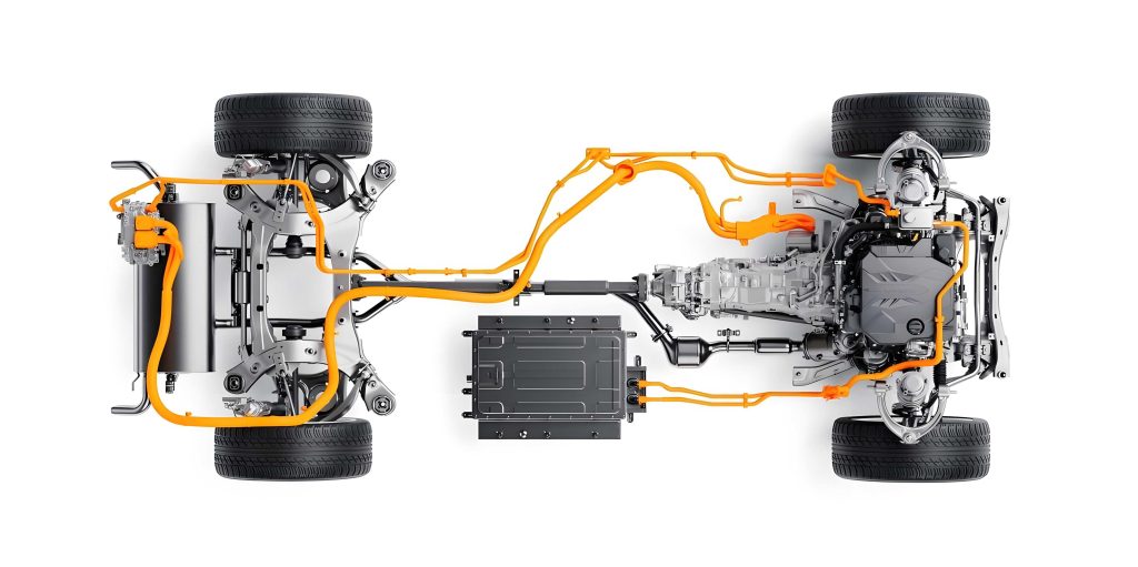
The series hybrid electric vehicle (HEV) architecture presents a compelling solution that effectively balances performance and cost considerations. This research proposes a P1+P4 series hybrid electric vehicle configuration. The system comprises an engine, an Integrated Starter-Generator (ISG), a traction motor, motor controllers, and a battery pack. The system’s architectural topology is illustrated in the figure above. The engine is coupled with the ISG motor and mounted in the front engine compartment, while the traction motor is integrated into the rear electric drive axle. A compact capacity power battery is positioned in the central section of the chassis, resulting in a relatively simple overall structure.
Within this hybrid electric vehicle system, the ISG motor serves a dual function: it can act as a motor to quickly crank the engine to an economical speed, and it can operate as a generator to charge the power battery or deliver electrical power to the traction motor via the motor controller. In all system operational modes, the engine functions solely as a generator. Vehicle propulsion is exclusively provided by the electric motor. This hybrid electric vehicle system enables several key functionalities on the vehicle, with the primary energy flow paths depicted below.
1. Pure Electric (EV) Driving: Under normal driving conditions with sufficient battery State of Charge (SOC), the vehicle can operate in pure electric mode. The engine and ISG motor remain off. Energy flows from the battery to the traction motor (Path ②).
2. Series HEV Mode (Normal Driving): During normal driving with insufficient battery SOC, the engine starts and drives the ISG generator to produce electricity. Energy flows from the engine to the ISG, then to the traction motor (Path ①).
3. Series HEV Mode (Hard Acceleration): During hard acceleration, the engine drives the ISG generator to produce electricity. Simultaneously, the power battery provides instantaneous high-power output to supplement the peak power demand. Energy flows from both the engine-generator set and the battery to the traction motor (Path ① + ②).
4. Regenerative Braking: During deceleration, the traction motor operates as a generator, converting kinetic energy into electrical energy, which is stored in the power battery. This process also enhances braking performance. Energy flows from the wheels back to the battery (Path ③).
Powertrain Performance and Economy Matching and Simulation
Engine and ISG Generator Parameter Calculation
The baseline vehicle parameters for this hybrid electric vehicle study are listed in Table 1. The high-efficiency Atkinson cycle engine and the ISG generator are core components of the series HEV. In this architecture, the generator converts the engine’s mechanical energy into electrical energy, serving as the sole source of electricity for the traction motor and other vehicle auxiliaries. Consequently, the performance and efficiency of the engine-generator set directly determine the vehicle’s fuel economy and dynamic performance. Therefore, the selection of engine and ISG generator specifications is typically based on meeting the vehicle’s requirements for sustained maximum speed on a level road and acceleration performance. The matching criteria are as follows:
1. The engine’s peak power must cover the ISG generator’s peak output.
2. The engine’s high-efficiency zone should overlap optimally with the ISG generator’s high-efficiency zone after mechanical coupling.
3. The ISG generator’s continuous and peak power ratings must satisfy the vehicle’s requirements for sustained maximum speed and acceleration performance, respectively.
The power required for maximum speed on a level road is given by:
$$P_{\text{max}} = \frac{V_{\text{max}}}{3600 \eta_T} \left( mgf + \frac{C_D A V_{\text{max}}^2}{21.15} \right)$$
where \(P_{\text{max}}\) is the power required at maximum vehicle speed \(V_{\text{max}}\) (km/h), \(m\) is the vehicle mass (kg), \(g\) is gravitational acceleration (m/s²), \(f\) is the rolling resistance coefficient, \(C_D\) is the aerodynamic drag coefficient, \(A\) is the frontal area (m²), and \(\eta_T\) is the drivetrain mechanical efficiency.
The power required for 0-100 km/h acceleration is given by:
$$P_t = \frac{V_f}{3600 \eta_T} \left( mgf + \frac{C_D A V_f^2}{21.15} + \frac{\delta m V_f}{3.6 \, dt} \left[ 1 – \frac{t_m – dt}{t_m} \right]^\chi \right)$$
where \(P_t\) is the power during hard acceleration, \(V_f\) is the final speed (100 km/h), \(t_m\) is the target 0-100 km/h acceleration time (s), \(\delta\) is the mass factor accounting for rotational inertia, \(dt\) is the design iteration step, and \(\chi\) is a fitting coefficient for the acceleration velocity profile.
Based on the vehicle parameters and a comprehensive calculation using the above formulas (1) and (2), while considering a reasonable design margin, the engine and ISG generator parameters were selected as shown in Table 2 and Table 3.
| Parameter | Value (HEV) |
|---|---|
| Curb Mass (kg) | 1450 |
| Gross Vehicle Mass (kg) | 1750 |
| Tire Rolling Radius (m) | 0.29 |
| Rolling Resistance Coefficient | 0.007 |
| Aerodynamic Drag Coefficient (C_D) | 0.36 |
| Frontal Area (m²) | 2.44 |
| Sustained Max Speed (km/h) | 135 |
| 0-100 km/h Acceleration Time (s) (Half Load) | 12 |
| Parameter | Specification |
|---|---|
| Displacement (L) | 1.6 |
| Max Power (kW) | 75 |
| Max Torque (N·m) | 145 |
| Peak Brake Thermal Efficiency (%) | 39.5 |
| Parameter | Specification |
|---|---|
| Rated/Peak Torque (N·m) | 127 / 143 |
| Rated/Peak Power (kW) | 40 / 75 |
| Rated/Peak Speed (r/min) | 3000 / 6000 |
| Peak Efficiency (%) | 94 |
Traction Motor Parameter Calculation and Selection
In a series hybrid electric vehicle system, the engine does not directly drive the wheels. Therefore, the traction motor must be sized to meet vehicle requirements for sustained maximum speed, hard acceleration performance, and low-speed high-torque capability.
The motor’s maximum speed requirement is determined by:
$$V_{\text{max}} = 0.377 \frac{n_{\text{max}} r}{i}$$
where \(n_{\text{max}}\) is the motor’s maximum speed (r/min), \(r\) is the tire rolling radius (m), and \(i\) is the final drive ratio.
Based on the vehicle parameters and a comprehensive calculation using formulas (1), (2), and (3), while considering a design margin, the traction motor parameters were selected as shown in Table 4.
| Parameter | Specification |
|---|---|
| Rated/Peak Power (kW) | 30 / 80 |
| Rated/Peak Torque (N·m) | 90 / 220 |
| Peak Speed (r/min) | 12000 |
| Peak Efficiency (%) | 94 |
| Final Drive Ratio | 9.7 |
Power Battery Parameter Calculation
For a series hybrid electric vehicle, parameters such as battery charge/discharge power and efficiency are critically linked to overall vehicle performance. Therefore, battery selection must carefully balance vehicle performance requirements with battery-specific energy and specific power. The key specifications for the power battery are listed in Table 5.
| Parameter | Specification |
|---|---|
| Battery Type | Lithium-ion |
| Nominal Voltage (V) | 350 |
| Battery Capacity (kWh) | 2.1 |
| Cooling Method | Liquid Cooled |
Simulation Modeling and Results
Based on the selected powertrain component parameters, a simulation model was built using specialized software. The model integrated the traction motor system, power battery system, engine, ISG generator, drivetrain, and vehicle dynamics. Mechanical, electrical, and control connections were established and computed. The simulation model of the prototype hybrid electric vehicle is conceptually represented in the figure below (represented textually).
The simulation results for fuel economy and dynamic performance are summarized in Table 6 and Table 7.
| Start Condition | Initial SOC (%) | Final SOC (%) | WLTC Fuel Consumption (L/100km) |
|---|---|---|---|
| Cold Start | 60 | 62.1 | 5.13 |
| Performance Metric | Simulation Result | Design Target |
|---|---|---|
| Max Speed – Curb Weight (km/h) | 135.3 | 135 |
| 0-100 km/h Acceleration Time (s) | 11.7 | 12 |
| Max Gradeability – GVW (%) | 30 | 30 |
The simulation data indicates that this hybrid electric vehicle equipped with the series hybrid system achieves a WLTC cycle fuel consumption of 5.13 L/100 km and a 0-100 km/h acceleration time of 11.7 seconds. The simulation confirms that the performance of this hybrid electric vehicle, in terms of both dynamics and fuel economy, is superior to that of the original internal combustion engine vehicle.
Prototype Vehicle Performance and Economy Testing
Dynamic Performance Testing
Acceleration performance was initially tested at a proving ground. The preliminary result for the 0-100 km/h acceleration time was 11.8 seconds, closely matching the simulation prediction.
Fuel Economy Testing
The vehicle’s fuel consumption was measured on a chassis dynamometer using the Worldwide Harmonized Light Vehicles Test Cycle (WLTC) procedure, as specified in standards such as “GB 18352.6-2016”. The WLTC cycle consists of four phases: Low, Medium, High, and Extra High speed segments. The test data results are presented in Table 8, comparing the hybrid electric vehicle (HEV) with the original internal combustion engine (ICE) vehicle.
| Vehicle | Low Phase (L/100km) | Medium Phase (L/100km) | High Phase (L/100km) | Extra High Phase (L/100km) | Composite (L/100km) |
|---|---|---|---|---|---|
| Original ICE Vehicle | 9.15 | 6.37 | 6.22 | 7.33 | 7.1 (Measured) |
| Series HEV Prototype | 0 (EV mode) | 4.98 | 5.07 | 7.35 | 5.2 |
Table 9 provides context by showing the evolving regulatory targets for low fuel consumption vehicles, against which this hybrid electric vehicle can be evaluated.
| Year | 2022 | 2023 | 2024 | 2025+ |
|---|---|---|---|---|
| Target Multiplier | 120% | 115% | 108% | 100% |
| Target Value (L/100km) | 5.84 | 5.59 | 5.25 | 4.86 |
From the test results, retrofitting the original vehicle with the series hybrid electric vehicle system yielded a measured fuel consumption reduction of 1.9 L/100 km, representing a 26.7% improvement. The measured 0-100 km/h acceleration time of 11.8 seconds shows a 21% improvement over the original vehicle’s 15 seconds. All key performance indicators surpassed those of the original ICE vehicle, meeting the predefined engineering objectives. Notably, the fuel consumption level of this hybrid electric vehicle meets the target set for low-consumption vehicles in 2024.
Conclusion
In summary, the series hybrid electric vehicle (HEV) system offers distinct performance advantages. A key benefit is the decoupling of engine speed from vehicle speed. This allows the engine to operate for extended periods at its optimal point on the Brake Specific Fuel Consumption (BSFC) map. This characteristic is particularly advantageous in real-world driving conditions, making it easier to maintain engine operation in its most efficient region. Consequently, the performance demands placed on the engine in this hybrid electric vehicle are generally lower than in a conventional gasoline-powered vehicle.
Due to the decoupling of the engine from the drivetrain, the vehicle can achieve driving dynamics comparable to a pure electric vehicle, including abundant torque, rapid response, and smooth acceleration. The application of high-efficiency components—the Atkinson cycle engine, ISG motor, traction motor, and controllers—combined with sophisticated vehicle control strategies, enables this hybrid electric vehicle architecture to comply with current and near-future fuel consumption regulations for energy-efficient vehicles. This research demonstrates the viability of a P1+P4 series hybrid electric vehicle as a structurally simple and cost-effective solution for significant fuel savings and performance enhancement during the industry’s transition towards full electrification.