
During the development and validation phase of a P2 parallel, non-plug-in mild hybrid electric vehicle, a critical driveline fault was encountered while testing the stationary power generation function. The fault manifested as a significant and potentially damaging motor overspeed event immediately upon the completion of a charging cycle.
1. Fault Phenomenon Description
The vehicle was configured for stationary generation, a common feature in hybrid electric vehicles designed to charge the high-voltage battery using the engine while the vehicle is at a standstill. The operational parameters were set as follows: transmission in neutral, parking brake engaged, and the driver initiating charging via a dedicated switch when the battery State of Charge (SOC) fell below a predefined lower threshold. The system operated nominally during the charging phase. However, the fault occurred at the precise moment charging was terminated, which was commanded when the SOC exceeded an upper threshold. At this instant, the electric motor speed rapidly exceeded its maximum permissible limit of 2,500 rpm, constituting a severe overspeed condition.
2. System Architecture and Principle Analysis
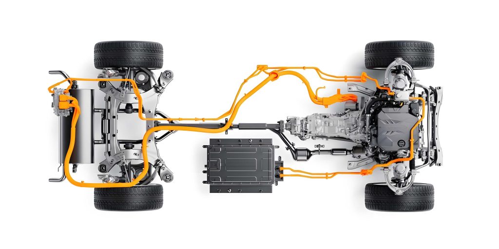
The P2 parallel hybrid electric vehicle architecture positions the electric motor between the engine and the transmission, coupled via a controllable clutch. This configuration is highly versatile for various hybrid modes. The stationary generation control logic for this hybrid electric vehicle is designed as follows:
- Initiation: When conditions are met (neutral, park brake, low SOC), the Hybrid Control Unit (HCU) engages the clutch, connecting the engine to the motor/generator.
- Charging Operation: The HCU commands the Engine Control Unit (ECU) to maintain a constant, efficient engine speed. Simultaneously, it commands the Motor Control Unit (MCU) to apply a constant negative torque (i.e., generating/charging torque). The engine works against this motor torque, converting fuel energy into electrical energy stored in the battery. During this phase, with the clutch engaged, the motor speed is equal to the engine speed:
$$ N_{motor}(t) = N_{engine}(t) \quad \text{for} \quad t < t_{stop} $$
where $t_{stop}$ is the charging termination time. - Termination: Upon reaching the target SOC, the HCU is designed to simultaneously command: a) Clutch disengagement, b) Engine torque reduction to idle, c) Motor torque demand to zero.
The fundamental cause of the overspeed can be deduced from first principles. An unloaded electric motor with a non-zero torque command will accelerate towards its speed limits. Therefore, the observed overspeed at the termination instant strongly suggested that the motor continued to receive a torque command even after the clutch was disengaged and it was mechanically decoupled from the engine.
3. Data Analysis and Root Cause Investigation
Data was captured from the vehicle’s CAN network during the fault event. The key parameters of the powertrain components are summarized below:
| Component | Parameter | Value | Unit |
|---|---|---|---|
| Engine | Rated Power | ~240 | kW |
| Idle Speed | ~600-800 | rpm | |
| Optimal BSFC Zone (for charging) | ~1300-1600 | rpm | |
| Electric Motor | Peak Power | ~50 | kW |
| Maximum Allowable Speed | 2500 | rpm | |
| Peak Torque | ~250 | Nm |
The CAN data trace revealed the sequence of events clearly. Prior to termination, the system was stable: engine speed constant at ~1500 rpm, motor speed equal to engine speed, and motor torque at a constant negative value (e.g., -120 Nm). At the termination command, the following was observed:
- The clutch status signal changed to “disengaged”.
- The engine speed command dropped to idle, and the engine speed began to decay.
- The commanded motor torque from the HCU changed to 0 Nm.
- However, the actual motor torque, as estimated or reported by the MCU, did not fall instantaneously to zero. It exhibited a gradual decay from the charging torque level towards zero.
- Concurrently, the motor speed, now decoupled from the engine, initially dipped slightly but then accelerated negatively (in the generating direction) to approximately -2550 rpm, exceeding the limit.
This data pinpointed the root cause: a lag or gradient in the motor torque response upon the exit from the stationary generation mode. The motor was effectively “coasting” with residual negative torque applied to its own rotor inertia, causing rapid acceleration. The governing dynamics post-clutch-disengagement can be simplified as:
$$ J_m \frac{d\omega_m}{dt} = T_m – T_{loss} \approx T_m $$
where $J_m$ is the motor rotor inertia, $\omega_m$ is the motor angular velocity, and $T_m$ is the motor torque. With $T_m$ still negative and non-zero, $\frac{d\omega_m}{dt}$ is negative, leading to increasing speed magnitude.
4. Control Strategy Flaw Analysis
The HCU software, modeled in Simulink/Stateflow, contained the logic for torque demand management. To ensure smooth powertrain operation and account for the different response times of the engine and motor, torque requests were typically filtered through rate limiters (gradients). The original logic for handling motor torque during stationary generation was flawed. The pseudocode is outlined below:
| Condition | Original Faulty Logic | Corrected Logic |
|---|---|---|
| Stationary_Gen_Flag = 1 (Active Charging) | Motor_Torque_Demand = Stationary_Gen_Torque (No gradient applied). Output is the full charging torque instantly. | Motor_Torque_Demand = Stationary_Gen_Torque (No gradient applied on entry either, for immediate response). |
| Transition: Flag 1 → 0 (Stop Command) | At the exact time step the flag becomes 0: 1. Motor_Torque_Demand is set to 0. 2. The *previous output* (which was Stationary_Gen_Torque) is fed into the gradient limiter module to ramp down to the new demand of 0. $$ T_{out}(k) = T_{out}(k-1) + \Delta \cdot sign(T_{demand}(k) – T_{out}(k-1)) $$ where $\Delta$ is the downward gradient. This causes a slow decay from non-zero. |
At the exact time step the flag becomes 0: 1. Motor_Torque_Demand is set to 0. 2. A one-time bypass is activated. The gradient limiter is *not* applied. The output torque is forced to the new demand value immediately. $$ T_{out}(k) = T_{demand}(k) = 0 $$ |
| Stationary_Gen_Flag = 0 (Inactive) | Normal gradient-limited operation resumes for any torque requests. | Normal gradient-limited operation resumes. |
The core issue was the management of the internal state of the gradient limiter block. At the stop instant, the block’s input changed from a high negative value to 0, but its internal state (previous output) was still the high negative value. Applying a down-ramp to this internal state resulted in the problematic slow torque decay. The correct behavior requires a discontinuous jump in the output torque at the mode exit, which is physically acceptable and necessary because the clutch disengagement creates a discontinuous change in the mechanical system boundary conditions.
5. Solution Implementation and Verification
The solution involved modifying the HCU software model to implement a controlled bypass of the gradient limiter specifically for the transition out of stationary generation mode. This was achieved by adding a conditionally triggered sample-and-hold or direct pass-through logic.
Mathematical Representation of the Solution:
Let $F_{sg}$ be the stationary generation flag (0 or 1). Let $T_{dem}$ be the raw torque demand and $T_{out}$ be the filtered output torque. Let $G(x, x_{prev}, \Delta_{up}, \Delta_{down})$ be the gradient limiting function. The corrected algorithm is:
$$
T_{out}(k) =
\begin{cases}
T_{dem}(k) & \text{if } F_{sg}(k) = 1 \\
T_{dem}(k) & \text{if } (F_{sg}(k)=0) \text{ and } (F_{sg}(k-1)=1) \\
G(T_{dem}(k), T_{out}(k-1), \Delta_{up}, \Delta_{down}) & \text{otherwise}
\end{cases}
$$
The second condition implements the critical one-step bypass at the moment the flag falls.
Simulation Results: A comparative simulation was run before and after the change. The results are summarized below:
| Event | Original Logic (Faulty) | Corrected Logic |
|---|---|---|
| Charging Start (Flag 0→1) | Torque jumps immediately to target charging torque. Slightly abrupt but acceptable. | Torque jumps immediately to target charging torque (preserving fast response for mode entry). |
| Charging Stop (Flag 1→0) | Torque ramps down from charging torque to 0 over ~500ms. With clutch disengaged, this causes motor overspeed. | Torque drops instantaneously from charging torque to 0. Motor coasts to stop without driven torque. |
| Post-Stop Motor Speed | Accelerates beyond -2500 rpm. | Decays smoothly to 0 rpm from the last coupled speed. |
Vehicle Test Validation: The updated software was compiled and flashed onto the vehicle’s HCU. Repeated tests of the stationary generation function were conducted. The data confirmed the resolution of the fault. Key observations from the validation test are quantified below:
| Parameter | At Time $t_{stop} – \delta$ (Charging) | At Time $t_{stop}$ (Command Issued) | At Time $t_{stop} + \Delta t$ (Result) |
|---|---|---|---|
| HCU Motor Torque Command | -120 Nm | 0 Nm | 0 Nm |
| MCU Motor Torque Feedback | ~ -118 Nm | < 5 Nm | ~ 0 Nm |
| Clutch Status | Engaged | Disengaged | Disengaged |
| Engine Speed | 1500 rpm | Begin decay to idle | ~700 rpm (idle) |
| Motor Speed | 1500 rpm | 1500 rpm (initial) | Decaying smoothly to 0 rpm |
| Peak Motor Speed Magnitude | 1500 rpm | N/A | < 1600 rpm (No overshoot) |
The data shows that the motor torque was effectively removed at the same instant as the clutch disengagement. Consequently, the motor speed, free from any driving torque, simply coasted down due to internal losses and electromagnetic drag, never approaching the overspeed limit. This validated the effectiveness of the control strategy update for this hybrid electric vehicle application.
6. Conclusion and Broader Implications for Hybrid Electric Vehicle Development
This investigation into a motor overspeed fault in a P2 hybrid electric vehicle during stationary generation shutdown highlights a critical aspect of hybrid powertrain management: the precise coordination of discrete mode transitions with continuous torque control. The fault was rooted not in hardware failure but in a subtle software logic error concerning the management of torque gradient limits during a specific state change.
The resolution underscores several important principles for developing robust control systems for hybrid electric vehicles:
- Mode-Specific Gradient Handling: Torque smoothing via rate limiters is essential for drivability and component protection. However, these limiters must be conditionally bypassed when the mechanical system configuration changes abruptly (e.g., clutch engagement/disengagement). The system dynamics before and after such an event are fundamentally different, and the control logic must reflect this discontinuity.
- System-Level Integration Testing: The fault escaped earlier unit and model-in-the-loop (MIL) testing because it emerged from the complex interaction between the controller’s software state and the physical vehicle’s response. This emphasizes the indispensable role of rigorous Hardware-in-the-Loop (HIL) testing and real-world validation, where the full closed-loop behavior, including component dynamics and communication delays, can be evaluated.
- Defense-in-Depth: While the primary fix was implemented at the HCU level, the importance of independent safety monitors is clear. The Motor Control Unit (MCU) should have, and likely did have, an independent overspeed protection logic that would have eventually intervened (e.g., by derating torque or initiating a safe shutdown). However, relying solely on such last-line defenses is poor practice; the root cause in the supervisory controller must be addressed to ensure system reliability and longevity.
This case study serves as a valuable reference for troubleshooting similar torque coordination issues in hybrid electric vehicles and other complex mechatronic systems. It demonstrates a structured approach to fault analysis: starting from the physical symptom, through system principle review, detailed data analysis, down to the inspection of the implemented control logic, and finally, verifying the fix through simulation and physical test. For engineers working on the integration and calibration of hybrid electric vehicle powertrains, paying meticulous attention to the torque handover and state transition logic at the boundaries of all operational modes is paramount to ensuring safe, reliable, and predictable vehicle behavior.