
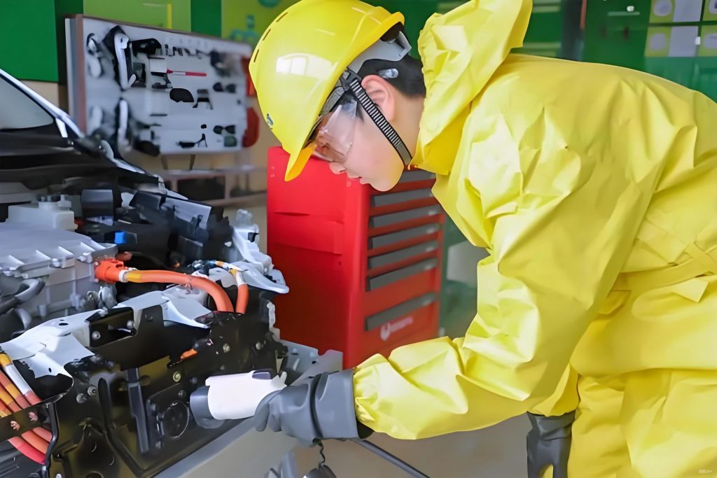
In my years of experience in EV repair, I have found that the power battery system is one of the most critical components in electric vehicles. Understanding its intricacies is essential for anyone involved in electrical car repair. This system not only stores energy but also manages it efficiently to ensure safety, performance, and longevity. Today, I will delve into the core aspects of the power battery system, focusing on battery modules, control units, management functions, and electrical interfaces. By incorporating tables and formulas, I aim to provide a comprehensive guide that highlights key concepts in EV repair and electrical car repair.
The power battery system in electric vehicles consists of multiple battery modules, each monitored by specialized control units. For instance, in some models, a battery module control unit manages several modules, communicating via CAN bus with higher-level controllers. This setup ensures precise monitoring and control, which is vital for effective EV repair. Let me start by discussing the battery module control units and their roles. In a typical configuration, there might be 12 battery module control units, each overseeing three battery modules. This hierarchical management allows for detailed supervision of voltage, current, and temperature, preventing issues like overcharging or overheating. As an EV repair technician, I often use diagnostic tools to interface with these units, checking for faults in the communication lines or sensor readings. Proper maintenance here can prevent costly repairs down the line.
To better illustrate the distribution of control units, consider the following table that summarizes a hypothetical battery module control system. This table is based on common practices in EV repair and electrical car repair scenarios:
| Control Unit ID | Managed Battery Modules | Primary Functions |
|---|---|---|
| J1208 | 1, 2, 3 | Voltage monitoring, temperature sensing |
| J1209 | 4, 5, 6 | Current regulation, fault detection |
| J1210 | 7, 8, 9 | Data communication via CAN bus |
| J1211 | 10, 11, 12 | Overvoltage and undervoltage protection |
| J1212 | 13, 14, 15 | Thermal management integration |
| J1213 | 16, 17, 18 | Balancing control initiation |
| J1214 | 19, 20, 21 | Insulation resistance monitoring |
| J1215 | 22, 23, 24 | Relay control for charging cycles |
| J1216 | 25, 26, 27 | State of Charge (SOC) estimation support |
| J1217 | 28, 29, 30 | Collision safety response |
| J1218 | 31, 32, 33 | Heating and cooling coordination |
| J1219 | 34, 35, 36 | Low-voltage interface management |
Moving on, the battery management system (BMS) is the brain behind the power battery system. In EV repair, I frequently encounter situations where BMS failures lead to reduced range or safety hazards. The BMS performs multiple functions, including overvoltage, undervoltage, overcurrent, and thermal protection. It also handles relay control, SOC estimation, charge management, cell balancing, fault alerting, and communication with other vehicle controllers. For example, during charging, if the voltage difference between cells exceeds a threshold—say, 1%—the BMS initiates balancing to equalize the charges. This is crucial in electrical car repair to prevent premature battery degradation. The SOC estimation is often calculated using formulas that integrate current and voltage measurements. A common approach involves the Coulomb counting method, which can be expressed as:
$$ SOC(t) = SOC_0 – \frac{1}{C_n} \int_0^t \eta I(\tau) d\tau $$
where \( SOC(t) \) is the state of charge at time \( t \), \( SOC_0 \) is the initial state of charge, \( C_n \) is the nominal capacity of the battery, \( \eta \) is the Coulombic efficiency, and \( I(\tau) \) is the current at time \( \tau \). This formula is fundamental in EV repair for diagnosing battery health and predicting range. Additionally, the BMS monitors insulation resistance to prevent electrical faults. The insulation resistance \( R_{ins} \) can be derived from voltage measurements across the high-voltage system:
$$ R_{ins} = \frac{V_{meas}}{I_{leak}} $$
where \( V_{meas} \) is the measured voltage and \( I_{leak} \) is the leakage current. Regular checks of this parameter are part of routine electrical car repair procedures to ensure safety.
Another key aspect in EV repair is the balancing control within the BMS. Imagine a scenario where one cell in a module reaches full charge before others; the BMS discharges that cell slightly to allow continued charging of the entire pack. This process maximizes the battery’s usable capacity. The balancing current \( I_{bal} \) can be modeled based on the voltage difference \( \Delta V \) between cells:
$$ I_{bal} = k \cdot \Delta V $$
where \( k \) is a proportionality constant dependent on the battery chemistry and design. In my work with electrical car repair, I have seen how improper balancing leads to uneven wear, reducing the overall battery life. The BMS also handles thermal management, activating cooling or heating systems based on temperature inputs. For instance, if the battery temperature \( T \) exceeds a safe limit \( T_{max} \), the BMS might reduce the allowable current \( I_{max} \) to prevent damage:
$$ I_{max} = I_{rated} \cdot e^{-\alpha (T – T_{ref})} $$
where \( I_{rated} \) is the rated current, \( \alpha \) is a thermal coefficient, and \( T_{ref} \) is the reference temperature. This kind of proactive management is why BMS is central to reliable EV repair.
Now, let’s discuss the high-voltage and low-voltage electrical interfaces in the power battery system. These are critical points for inspection during electrical car repair. High-voltage cables connect components like the battery to the motor and charging unit, and they often include shielding to prevent electromagnetic interference. The bending radius of these cables is crucial; if bent too sharply, the shielding can be damaged, leading to insulation faults. The minimum bending radius \( R_{min} \) is typically defined as a multiple of the cable’s outer diameter \( d \):
$$ R_{min} = n \cdot d $$
where \( n \) is a factor ranging from 5 to 10, depending on the cable specifications. In EV repair, I always advise technicians to follow manufacturer guidelines to avoid such issues. High-voltage connectors feature internal and external contact protection, with color-coded elements for easy identification. For example, gray end caps might indicate shielded cables, while turquoise ones denote unshielded versions. This simplifies diagnostics in electrical car repair. The low-voltage interface, usually a multi-pin connector, links the battery to the vehicle’s low-voltage network, providing power to the BMS and facilitating communication signals.
To summarize the electrical interfaces, here is a table that outlines common connections and their functions in EV repair contexts:
| Interface Type | Connection Points | Key Features | Repair Considerations |
|---|---|---|---|
| High-Voltage Interface | Battery to motor, charging unit | Shielded cables, contact protection | Check for insulation resistance, avoid sharp bends |
| Low-Voltage Interface | Battery to vehicle network | Multi-pin connector, signal transmission | Verify voltage levels, inspect for corrosion |
| DC Charging Interface | Direct to charging port | High-current capacity, safety locks | Test for proper engagement, monitor thermal rise |
In EV repair, understanding the integration of these interfaces is essential. For instance, the high-voltage switch box performs periodic insulation checks—every 30 seconds in some systems—to detect potential faults. The insulation resistance \( R_{ins} \) must meet minimum standards, often specified by regulations. If \( R_{ins} \) falls below a threshold \( R_{min} \), it triggers a fault code, requiring immediate attention in electrical car repair. This can be calculated as:
$$ R_{ins} > R_{min} = \frac{V_{system}}{I_{leak,max}} $$
where \( V_{system} \) is the system voltage and \( I_{leak,max} \) is the maximum allowable leakage current. Regular monitoring helps prevent hazardous situations, making it a staple in EV repair protocols.
Furthermore, the BMS coordinates with other vehicle systems, such as the thermal management control unit, to activate cooling pumps or heaters based on battery temperature. This collaboration ensures optimal performance and safety. In my electrical car repair practice, I have seen how failures in this coordination lead to overheating, especially in fast-charging scenarios. The heat generation \( Q \) in a battery cell can be approximated using Joule’s law and internal resistance \( R_{int} \):
$$ Q = I^2 \cdot R_{int} \cdot t $$
where \( I \) is the current and \( t \) is time. Managing this heat is critical, and the BMS may limit charging rates accordingly. For example, the maximum charging current \( I_{charge,max} \) might be adjusted based on temperature \( T \):
$$ I_{charge,max} = I_{base} \cdot \left(1 – \beta |T – T_{opt}|\right) $$
where \( I_{base} \) is the base current, \( \beta \) is a temperature coefficient, and \( T_{opt} \) is the optimal temperature. This equation is useful in EV repair for diagnosing charging issues related to thermal constraints.
As we delve deeper into EV repair, it’s important to consider the overall system reliability. The power battery system’s design includes redundancy and fault tolerance, but regular maintenance is key. For instance, cell balancing should be checked during service intervals. The balance efficiency \( \eta_{bal} \) can be expressed as the ratio of balanced energy to total energy:
$$ \eta_{bal} = \frac{E_{balanced}}{E_{total}} \times 100\% $$
where \( E_{balanced} \) is the energy redistributed during balancing and \( E_{total} \) is the total energy capacity. In electrical car repair, aiming for high \( \eta_{bal} \) values—above 95%—ensures longer battery life. Additionally, the BMS continuously estimates the battery’s state of health (SOH), which correlates with capacity fade over time. A simple SOH model might involve the current capacity \( C_{current} \) relative to the initial capacity \( C_{initial} \):
$$ SOH = \frac{C_{current}}{C_{initial}} \times 100\% $$
Monitoring SOH helps in predicting replacement needs, a common task in EV repair.
In conclusion, the power battery system is a complex yet fascinating component in electric vehicles, and mastering its details is crucial for effective EV repair and electrical car repair. From battery module control units to the BMS and electrical interfaces, each element plays a vital role in ensuring safety, efficiency, and durability. By applying the formulas and tables discussed, technicians can better diagnose issues, perform maintenance, and extend the life of EV batteries. As the industry evolves, continuous learning in EV repair will be essential to keep up with advancements in battery technology. Remember, a thorough understanding of these systems not only enhances repair accuracy but also contributes to the broader adoption of electric vehicles by ensuring their reliability and performance.