
As the automotive industry evolves towards electrification, an increasing number of hybrid electric vehicles (HEVs) are entering the market. A primary advantage of the hybrid electric vehicle is its enhanced fuel economy. However, the very nature of its powertrain, which involves switching between the electric motor and the internal combustion engine (ICE) operating modes—such as during engine start and stop events—can introduce significant drivability issues. These manifest as jerks (sudden, high-amplitude longitudinal acceleration oscillations) and shudders (subsequent, lower-amplitude oscillations), severely compromising driving and riding comfort. Traditional mitigation strategies often focus on the powertrain control unit, smoothing torque request gradients to reduce excitation. While this approach can alleviate jerks and shudders, it inherently trades off against vehicle responsiveness, leading to a sluggish pedal feel.
To address this compromise, this research adopts a holistic hardware-oriented perspective. Instead of solely relying on control software limitations, we focus on the physical characteristics of the driveline components. The core objective is to optimize these hardware parameters to passively dampen the vibrations arising from mode transitions, thereby improving drivability without sacrificing dynamic response. We establish a detailed parametric drivability simulation model for a hybrid electric vehicle. Through systematic sensitivity analysis of key component parameters—such as stiffness, damping, and backlash—we identify their individual and combined influences on jerk and shudder metrics. Subsequently, a comprehensive multi-parameter optimization is performed to derive a feasible component specification set that minimizes drivability discomfort.
1. Introduction and Problem Definition
The driving experience in a hybrid electric vehicle is characterized by its multiple operating modes: pure electric (EV), series/range-extended (EREV), and parallel hybrid. Transitions between these modes are frequent. For instance, during a tip-in event where the driver presses the accelerator pedal, the vehicle may shift from EV mode to a mode requiring engine operation. This triggers an engine start, where the motor applies a cranking torque to the engine, inducing vibrations. Conversely, during deceleration or braking, the drive motor can provide regenerative braking (negative torque), and a subsequent tip-in can cause a rapid torque reversal from negative to positive. The presence of driveline backlash (gear lash) means this reversal first takes up the lash before applying drive torque, resulting in an impulsive force upon gear contact. These excitations propagate through the driveline and suspension paths to the wheels, causing longitudinal acceleration fluctuations perceived as jerk and shudder. This study specifically targets the improvement of drivability during such aggressive tip-in events with potential mode changes in a hybrid electric vehicle.
2. Methodology: Drivability Modeling and Analysis Framework
2.1. Drivability Simulation Model
The vehicle is modeled as a multi-degree-of-freedom (DOF) viscous damping system. The equations of motion for this lumped-parameter model are derived from the force transmission paths during a tip-in event with engine start. The general form of the vibration differential equation is given by:
$$ M\ddot{x} + C\dot{x} + Kx = F(t) $$
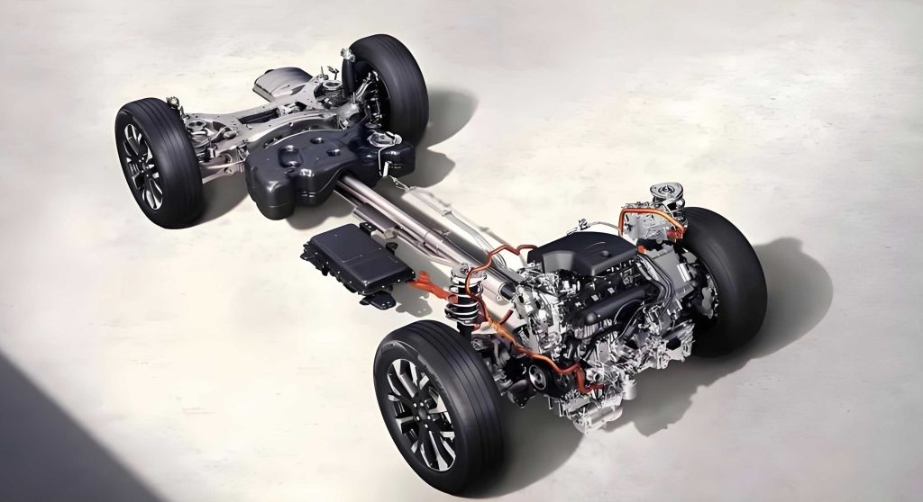
where \( M \) is the mass matrix, \( C \) is the damping matrix, \( K \) is the stiffness matrix, \( x \) is the displacement vector, and \( F(t) \) is the time-dependent excitation force vector from the powertrain (motor and engine torque). The excitation force propagates through two primary paths: 1) via the drive shafts and knuckles to the wheels, and 2) via the engine mounts, subframe, and control arms to the wheels. Mechanical backlashes in the driveline are explicitly modeled as nonlinear elements that induce impulsive forces when the torque direction reverses and the lash is taken up.
The model requires a comprehensive set of input parameters covering the entire vehicle system. The key parameters are categorized and listed in the table below.
| Subsystem | Parameter | Unit |
|---|---|---|
| Vehicle Chassis | Test Mass | kg |
| Axle Load Distribution | % | |
| Wheelbase | mm | |
| Rolling Resistance | N | |
| Unsprung Mass (Front/Rear) | kg | |
| Tire | Rotational Inertia | kg·m² |
| Longitudinal Stiffness | N/mm | |
| Vertical Stiffness | N/mm | |
| Damping (X, Y, Z directions) | N/(m/s) | |
| Suspension | Spring Stiffness (Front/Rear) | N/mm |
| Damper Damping (Front/Rear) | N/(m/s) | |
| Driveshaft | Torsional Stiffness | Nm/rad |
| Torsional Damping | Nm/(rad/s) | |
| Rotational Inertia | kg·m² | |
| Transmission | Driveline Backlash | deg |
| Input Shaft Torsional Stiffness | Nm/rad | |
| Gear Damping | Nm/(rad/s) | |
| Powertrain (ICE + Electric) | Engine Cranking Torque Profile | Nm |
| Motor Torque Rise/Fall Rate | Nm/s | |
| Total Powertrain Mass & Inertia | kg, kg·m² | |
| Motor Peak Torque/Power | Nm, kW | |
| Mounting System | Number of Mounts | – |
| Mount Location Coordinates | mm | |
| Mount Stiffness (3 directions) | N/mm | |
| Mount Damping (3 directions) | N/(m/s) |
2.2. Optimization Problem Formulation
The goal is to minimize the objective functions defined by the jerk magnitude \( s \) and the shudder magnitude \( j \), which are functions of key hardware parameters. The parameters considered for optimization include: driveline backlash \( \alpha \), driveshaft torsional damping \( C_1 \) and stiffness \( K_1 \), and the stiffness \( K_2, K_3 \) and damping \( C_2, C_3 \) of the powertrain mounts (specifically at the transmission and engine sides). The formal optimization problem is stated as:
$$
\begin{aligned}
& \min \quad (s(\alpha, K_i, C_i), \quad j(\alpha, K_i, C_i)) \\
& \text{subject to} \quad K_i \geq K_{i,\text{min}}, \quad C_i \geq 0
\end{aligned}
$$
where \( i \) indexes the relevant components. The constraints ensure that stiffness values remain above their minimum allowable limits for structural and functional integrity. The solution approach involves first conducting single-parameter sensitivity studies to understand individual effects, followed by a combined multi-parameter optimization.
3. Single-Parameter Sensitivity Analysis
This section analyzes the effect of varying one parameter at a time relative to the baseline hybrid electric vehicle configuration.
3.1. Transmission Driveline Backlash (\( \alpha \))
Backlash is a critical factor. A larger gap means greater kinetic energy is built up before the gears re-engage, leading to a stronger impact. Reducing the driveline backlash by 1 degree from the baseline shows a clear improvement. The simulation results indicate the jerk amplitude \( s \) decreased by 0.11 m/s² and the shudder \( j \) decreased by 0.04 m/s². This confirms that minimizing gear lash is a direct and effective way to improve drivability in a hybrid electric vehicle.
3.2. Driveshaft Torsional Damping (\( C_1 \))
While inherent driveshaft damping is low, it can be significantly increased by adding tuned dampers or absorbers. Varying \( C_1 \) by ±50% reveals its sensitivity. Increasing damping by 50% reduced jerk by 0.08 m/s² and shudder by 0.06 m/s². Conversely, decreasing damping worsened both metrics. Therefore, increasing driveshaft damping is beneficial for attenuating both jerk and shudder.
3.3. Driveshaft Torsional Stiffness (\( K_1 \))
Varying driveshaft stiffness presents a trade-off. Increasing \( K_1 \) by 15% slightly increased the initial jerk amplitude (+0.03 m/s²) but accelerated its decay, reducing shudder by 0.04 m/s². Decreasing \( K_1 \) by 15% reduced the initial jerk (-0.07 m/s²) but slowed the decay, leading to increased shudder (+0.02 m/s²). This indicates that optimizing stiffness alone cannot simultaneously improve both objectives; it must be paired with damping optimization.
4. Combined Multi-Parameter Optimization
4.1. Driveshaft Stiffness and Damping Co-optimization
Based on the single-parameter findings, we investigate combined changes to \( K_1 \) and \( C_1 \). Two scenarios are compared against the baseline: 1) Increasing both \( K_1 \) (+15%) and \( C_1 \) (+50%); 2) Decreasing \( K_1 \) (-15%) and increasing \( C_1 \) (+50%).
Scenario 1 yielded a significant shudder reduction (0.07 m/s²) but negligible jerk improvement (0.01 m/s²). Scenario 2, however, provided a superior combined result: jerk was reduced by 0.13 m/s² and shudder by 0.06 m/s². This demonstrates that a softer, more damped driveshaft is more effective for overall drivability refinement in the context of a hybrid electric vehicle’s aggressive transients.
4.2. Powertrain Mount Stiffness and Damping Optimization
The mounting system is the primary path for transmitting engine start vibrations to the body. A hybrid electric vehicle powertrain is typically heavier and subject to higher, faster torque changes than a conventional one, often necessitating more mounts (e.g., separate lateral restraints on both engine and transmission sides). We optimize the stiffness (\( K_2, K_3 \)) and damping (\( C_2, C_3 \)) of these mounts, particularly in the longitudinal (X) direction which primarily affects fore-aft vibration.
For the transmission-side mount:
- Increasing only damping \( C_2 \) by 25% improved shudder by 0.05 m/s² but did not affect jerk.
- Decreasing only stiffness \( K_2 \) by 25% improved both jerk (0.06 m/s²) and shudder (0.03 m/s²).
- The combined action of decreasing \( K_2 \) by 25% and increasing \( C_2 \) by 25% was optimal, reducing jerk by 0.06 m/s² and shudder by 0.07 m/s².
A similar but less pronounced trend was observed for the engine-side mount due to its initially lower stiffness. Reducing \( K_3 \) and increasing \( C_3 \) by 25% each reduced jerk by 0.03 m/s² and shudder by 0.06 m/s².
5. Sensitivity Coefficients and Comprehensive Solution
The relative sensitivity of each parameter to the objectives can be expressed as a coefficient: the percentage change in the objective divided by the percentage change in the parameter. A summary of the key sensitivity findings is presented below. The coefficient’s magnitude indicates the parameter’s influence.
| Parameter | Symbol | Sensitivity for Jerk (s) | Sensitivity for Shudder (j) | Combined Sensitivity (s+j) |
|---|---|---|---|---|
| Driveline Backlash | \( \alpha \) | 1.68 | 2.75 | 2.11 |
| Driveshaft Damping | \( C_1 \) | -0.44 | -1.50 | -0.87 |
| Driveshaft Stiffness | \( K_1 \) | 1.30 | -1.67 | 0.11 |
| Trans. Mount Stiffness | \( K_2 \) | 0.67 | 1.50 | 1.00 |
| Trans. Mount Damping | \( C_2 \) | 0.00 | -2.50 | -1.00 |
| Engine Mount Stiffness | \( K_3 \) | 0.33 | 1.50 | 0.80 |
| Engine Mount Damping | \( C_3 \) | -0.11 | -2.00 | -0.87 |
The comprehensive optimal strategy integrates all beneficial changes identified through the sensitivity analysis. The table below compares the performance of individual and combined optimizations against the baseline hybrid electric vehicle configuration.
| Scheme | Optimization Action | Jerk, s (m/s²) | Shudder, j (m/s²) | Reduction vs. Baseline |
|---|---|---|---|---|
| #0 | Baseline Configuration | 0.36 | 0.08 | – |
| #1 | Reduce backlash \( \alpha \) by 1° | 0.25 | 0.04 | 30.6% / 50.0% |
| #2 | Increase driveshaft damping \( C_1 \) by 50% | 0.28 | 0.02 | 22.2% / 75.0% |
| #7 | Decrease \( K_1 \) 15% & Increase \( C_1 \) 50% | 0.23 | 0.02 | 36.1% / 75.0% |
| #8 | Decrease trans. mount stiffness \( K_2 \) 25% & Increase damping \( C_2 \) 25% | 0.30 | 0.01 | 16.7% / 87.5% |
| #9 | Combined Optimization (All actions from #1, #7, #8) | 0.11 | 0.01 | 69.4% / 87.5% |
The final combined optimization (Scheme #9) yields a dramatic improvement, reducing jerk by 69.4% and shudder by 87.5% compared to the baseline. This demonstrates the significant potential of a systematic hardware parameter optimization approach for enhancing the drivability of a hybrid electric vehicle. Implementation of these optimized parameters (reduced backlash, softer and more damped driveshaft, and optimized mount properties) on a physical prototype vehicle validated the simulation results, showing a measured reduction in longitudinal acceleration fluctuations consistent with the model predictions.
6. Conclusion and Future Work
Drivability has become a critical attribute for customer satisfaction in modern vehicles. For hybrid electric vehicles, the challenge is pronounced due to frequent powertrain mode shifts. This study successfully established a simulation-based framework to address jerk and shudder by optimizing the physical parameters of driveline and mounting components. Sensitivity analysis revealed the distinct and often interacting effects of parameters like backlash, stiffness, and damping. The proposed comprehensive optimization strategy, focusing on minimizing backlash, tuning driveshaft properties for optimal damping with reduced stiffness, and softening and increasing damping in key powertrain mounts, proved highly effective in suppressing unwanted longitudinal vibrations without impairing torque response.
This work focused on longitudinal dynamics. Future research directions for hybrid and electric vehicles include investigating the coupling between longitudinal and vertical dynamics (e.g., driveline vibrations exciting body modes) and expanding the optimization to include more complex mount geometries (hydraulic mounts) and active damping systems for even greater refinement across a wider range of driving scenarios.