
The quest for superior fuel economy is a central challenge in the development of hybrid cars. These vehicles, equipped with multiple power sources like an internal combustion engine and electric motors, present a complex control problem: how to optimally split power or torque between these sources in real-time to minimize overall energy consumption. This paper presents a systematic, efficiency-focused methodology for determining power split rules in hybrid cars, applicable to series, parallel, and series-parallel architectures. The core principle is to treat the battery as a temporary energy buffer and evaluate the combined “mileage” obtained from both direct fuel use and the electric energy stored or released, ensuring battery state-of-charge (SOC) neutrality over a cycle. By exhaustively analyzing all possible operating points and power flow paths, this method generates offline efficiency maps and corresponding optimal torque/power split maps. These maps can be directly implemented in the vehicle control unit, providing a theoretically sound foundation that reduces reliance on engineering heuristics and significantly shortens calibration development cycles for hybrid cars.
The proposed methodology is fundamentally an instantaneous optimization technique. It operates by determining, for every possible vehicle operating point defined by a speed and wheel torque demand, the relationship between engine fuel consumption and battery SOC change. The key innovation lies in converting battery power into an equivalent “pure electric range” that would be attainable with that energy. The control objective at each instantaneous point becomes maximizing this combined mileage—from both the direct engine work and the equivalent electric range from the battery activity. By calculating the system efficiency for all feasible power split decisions in each operational mode, optimal efficiency maps and their corresponding control maps are derived. These maps instruct the controller on the most efficient way to operate the hybrid powertrain, whether to charge the battery, discharge it, or use a combination of sources.
Hybrid Car Powertrain Architecture and Modes
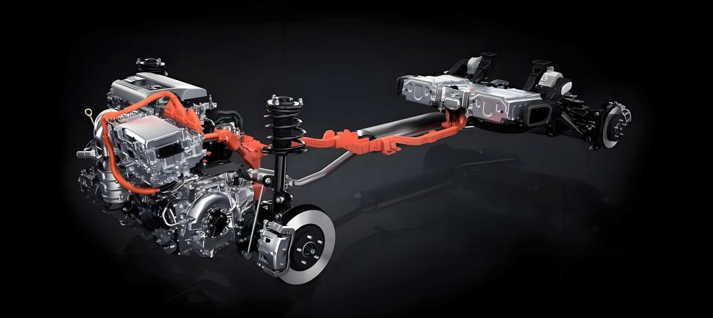
The efficiency analysis is demonstrated on a specific series-parallel hybrid car architecture, but the principles are broadly applicable. The system comprises an engine (ICE), a clutch (C1), two electric machines (EM1, EM2), and a multi-gear transmission system allowing various power flow paths. EM1 is connected to the engine via a fixed gear ratio ig and can couple to the driveline through two gear ratios (G1: i1, G2: i2) or a neutral position. EM2 is connected via its own fixed gear ratio i3. This configuration enables a variety of operational modes crucial for managing energy in a hybrid car, as summarized in the table below. This paper focuses on driving modes where power split decisions are critical; modes like regenerative braking or stationary generation are not covered in detail.
| Operational Mode | Engine (ICE) | Motor 1 (EM1) | Motor 2 (EM2) | Description |
|---|---|---|---|---|
| Pure Electric (EV) | OFF (0) | Drive (1) | Drive (1) | Vehicle powered solely by EM1 and/or EM2. |
| Series Charging | ON (1) | Generate (-1) | Drive (1) | Engine drives EM1 as generator. Power flows to battery and to EM2 for driving. |
| Direct Drive | ON (1) | Idle/Off (0) | Idle/Off (0) | Engine power goes directly to wheels, like a conventional vehicle. |
| Alternating Series | ON (1) | Generate (-1) | Drive (1) | A conceptual model: engine drives EM1 to generate power for both driving (via EM2) and charging the battery. The stored energy is later used in EV mode to maintain SOC balance. |
| Alternating Direct Drive | ON (1) | Generate (-1) | Off (0) | A conceptual model: engine power drives wheels directly, with surplus mechanical power used by EM1 to charge the battery. Stored energy is used later. |
| Parallel | ON (1) | Drive (1) | Drive (1) | Both engine and motors provide torque to the wheels simultaneously, consuming both fuel and battery energy. |
Note: (1) indicates the source is active/motoring; (0) indicates inactive; (-1) indicates generating.
Efficiency Analysis Methodology
The system efficiency analysis for a hybrid car integrates the efficiencies of the main components: the engine, electric machines (including their inverters), and the battery. Required inputs include vehicle parameters (wheel radius, gear ratios), component efficiency maps (engine BSFC, motor efficiency), torque/power limits, and battery parameters (open-circuit voltage, internal resistance).
Pure Electric Mode Efficiency
In pure electric mode, the hybrid car is powered by one or both motors. EM1 can operate in two gears (G1, G2) or be disconnected. For a given vehicle speed V (m/s) and wheel torque demand T_wheel (Nm), the optimal torque split between EM1 and EM2 and the optimal gear for EM1 are determined by maximizing the overall system efficiency. Let λ (between 0 and 1) represent the fraction of wheel torque provided by EM1’s path. The torques and speeds for EM1 (in G1) and EM2 are:
$$
t_{em1} = \frac{T_{wheel} \cdot \lambda}{i_1 \cdot i_0 \cdot i_g}, \quad n_{em1} = \frac{V \cdot 60 \cdot (i_1 \cdot i_0 \cdot i_g)}{3.6 \cdot 2 \pi r}
$$
$$
t_{em2} = \frac{T_{wheel} \cdot (1-\lambda)}{i_3 \cdot i_0}, \quad n_{em2} = \frac{V \cdot 60 \cdot (i_3 \cdot i_0)}{3.6 \cdot 2 \pi r}
$$
Where r is the wheel radius. The electrical power demand from the battery (gross) is the sum of the mechanical power for each motor divided by its efficiency η_motor at its operating point (t, n). The system efficiency for the EV_G1_EM2 mode is the ratio of wheel power to total electrical input power:
$$
\eta_{ev11}(V, T_{wheel}, \lambda) = \frac{P_{wheel}}{P_{elec}} = \frac{V \cdot T_{wheel}}{3.6 \cdot r \cdot 1000} \cdot \frac{1}{\left( \frac{t_{em1} \cdot n_{em1}}{9550 \cdot \eta_{em1}} + \frac{t_{em2} \cdot n_{em2}}{9550 \cdot \eta_{em2}} \right)}
$$
By discretizing V, T_wheel, and λ and performing a search, the optimal efficiency map η_ev11_opt(V, T) and the corresponding optimal torque split map λ_ev11_opt(V, T) are obtained. This process is repeated for EV mode with EM1 in G2 (η_ev21_opt) and for EM2-only driving (η_ev01_opt). Finally, for each (V, T) point, the highest efficiency among the three options is selected, yielding the global pure electric optimal efficiency map η_EV_opt(V, T), along with maps for the optimal gear and torque split.
Generating Efficiency
When the engine drives EM1 as a generator, the combined “generating efficiency” is the product of the engine efficiency and EM1’s generating efficiency at that operating point. The engine efficiency map η_eng(n_eng, t_eng) is first converted to a map based on engine speed and power η_I(n_eng, P_eng). The efficiency of EM1, when operating as a generator driven by the engine, is also mapped to engine coordinates η_em1_at_eng(n_eng, t_eng). The generating efficiency is then:
$$
\eta_{Gen}(n_{eng}, t_{eng}) = \eta_I(n_{eng}, P_{eng}) \cdot \eta_{em1\_at\_eng}(n_{eng}, t_{eng})
$$
This map is further transformed to be based on generating power P_gen and engine speed, denoted as η_G(n_eng, P_gen). For a given required generating power, the optimal engine speed that maximizes η_G is found, defining the generating optimal operating line (G-OOL).
Battery Charge/Discharge Efficiency
A simplified battery model with a constant internal resistance R_b is used. The open-circuit voltage is V_oc and the terminal voltage is V_t. For a charge power P_c (gross power into battery terminals), the net power stored is P_c_net. The charge current is I_c = P_c / V_t, and V_t = V_oc + I_c * R_b. Solving, the battery charge efficiency η_c is derived as:
$$
\eta_c(P_c) = \frac{V_{oc}}{V_t} = \frac{2}{1 + \sqrt{1 + \frac{4 R_b P_c}{V_{oc}^2}}}
$$
Similarly, for a discharge power P_d (net power from battery), the gross power from the battery chemistry is P_d_gross = I_d * V_t, with I_d = P_d / V_t and V_t = V_oc – I_d * R_b. The discharge efficiency η_d is:
$$
\eta_d(P_d) = \frac{V_t}{V_{oc}} = \frac{1 + \sqrt{1 – \frac{4 R_b P_d}{V_{oc}^2}}}{2}
$$
Alternating Series Mode Efficiency
This is a key conceptual mode for optimizing the hybrid car’s operation. It models a cycle where the engine generates power for a duration t_c. Part of this power is used to drive the wheels via EM2 (Series driving), and part charges the battery. The energy stored is later used in a pure electric (EV) mode for a duration t_d to maintain SOC balance, covering the same wheel power demand. The goal is to maximize the total distance (mileage) covered in the combined cycle (t_c + t_d) per unit of fuel consumed during t_c.
Let P_L be the wheel power demand. During the charging phase (t_c), the generating power P_gen must cover the wheel power (delivered via EM2 with efficiency η_ev01) plus the battery charge power P_c. The fuel power is P_f = P_gen / η_G, where η_G is the generating efficiency from the G-OOL corresponding to P_gen. During the EV phase (t_d), the wheel power P_L is supplied by the battery/both motors with the optimal pure EV efficiency η_EV_opt found earlier. SOC balance requires that the net energy change is zero:
$$
P_c \cdot \eta_c \cdot t_c = \frac{P_L}{\eta_{EV\_opt}} \cdot \frac{1}{\eta_d} \cdot t_d
$$
Solving for t_d and calculating the combined mileage efficiency (wheel energy per fuel energy) yields the Alternating Series system efficiency:
$$
\eta_{AltS} = \eta_G \cdot \eta_{ev01} \cdot \frac{P_L + \eta_c \cdot \eta_d \cdot \eta_{EV\_opt} \cdot P_c}{P_L + \eta_{ev01} \cdot P_c}
$$
For every vehicle operating point (V, T_wheel), a search is performed over all feasible generating/charging powers P_c (and thus P_gen). The combination that maximizes η_AltS is found. This yields the optimal efficiency map η_AltS_opt(V, T) and the corresponding optimal charging power map P_c_AltS_opt(V, T), which dictates the engine’s operating point. The equivalent fuel consumption rate for the electricity generated in this optimal state can be calculated as:
$$
CF_{AltS} = \frac{3600}{LHV \cdot \eta_G \cdot \eta_c}
$$
where LHV is the fuel’s lower heating value (~42,000 J/g for gasoline).
Alternating Direct Drive Mode Efficiency
This mode conceptually combines a direct drive phase with battery charging. During t_c, the engine power P_eng directly drives the wheels (with efficiency η_I at that operating point) and also provides mechanical power to EM1 for generating a charging power P_c. The SOC is balanced by an EV phase of duration t_d. The system efficiency is derived similarly:
$$
P_{eng} = P_L + \frac{P_c}{\eta_{em1\_gen}}
$$
$$
\eta_{AltD} = \eta_I \cdot \frac{P_L + \eta_c \cdot \eta_d \cdot \eta_{EV\_opt} \cdot \eta_{em1\_gen} \cdot P_c}{P_L + P_c}
$$
A search over P_c for each (V, T_wheel) point yields the optimal efficiency map η_AltD_opt and the optimal charging power map P_c_AltD_opt for this hybrid car mode. This analysis is performed for each available direct drive gear.
Parallel Mode Efficiency
In Parallel mode, both the engine and motors provide torque to the wheels simultaneously, consuming fuel and discharging the battery. A precise instantaneous optimization for this hybrid car mode is more complex as it directly consumes battery energy that was presumably stored optimally in other modes. A pragmatic approach is adopted: the “value” of the battery energy is considered equal to the average equivalent fuel consumption rate CF_avg derived from the optimal Alternating Series and Direct Drive modes. For a given vehicle point and an engine torque fraction λ_eng, the required motor torque and battery discharge power P_d_net are calculated. The battery gross discharge power is P_d_gross = P_d_net / η_d(P_d_net). The combined system efficiency for the hybrid car in parallel mode is then:
$$
\eta_{Para} = \frac{P_L}{\frac{P_{eng}}{\eta_I} + \frac{P_{d\_gross}}{CF_{avg} \cdot LHV / 3600}}
$$
A search over λ_eng yields the optimal parallel efficiency and torque split maps for each gear.
Synthesizing the Hybrid Control Strategy
After calculating the optimal efficiency maps (η_Series, η_AltS_opt, η_Direct, η_AltD_opt, η_Para_opt) for all relevant modes of the hybrid car, a final selection is made for every (V, T_wheel) point in the driving envelope: the mode with the highest efficiency is chosen. This results in a comprehensive hybrid rule-based control map. This map, along with the associated optimal torque split or power split maps for each mode, forms the core of the proposed efficiency-optimized control strategy for the hybrid car.
| Control Mode Decision Logic | Condition | Action |
|---|---|---|
| Electric Vehicle (EV) Mode | Battery SOC high OR driver request. | Use pure electric optimal efficiency map (η_EV_opt). Select gear and torque split from Gear_EV and λ_EV maps. |
| Charge Sustaining (CS) Mode | SOC low OR wheel power demand exceeds EM capability. | Query the synthesized Hybrid Rule Control Map. Based on selected mode (e.g., Alt. Series, Alt. Direct, Parallel), use the corresponding optimal power split map (P_c_opt) or torque split map (λ_eng_opt) to determine engine and motor setpoints. |
Experimental Validation and Results
The proposed efficiency-optimal strategy was implemented in a hybrid car and compared against a conventional rule-based baseline strategy on a chassis dynamometer over the WLTC cycle in charge-sustaining (CS) mode. The baseline strategy used fixed thresholds for speed, torque, and SOC to transition between heuristic rules for engine operation. The results demonstrated the effectiveness of the proposed method for the hybrid car.
The table below summarizes the fuel consumption comparison. To account for minor SOC differences at cycle end, the battery energy change was converted to an equivalent fuel consumption. The efficiency-optimal strategy showed a clear reduction in fuel use.
| Control Strategy | Battery Energy Change (kWh) | Equivalent Fuel Consumption (L/100km) | Relative Consumption |
|---|---|---|---|
| Baseline Strategy | -0.051 | 5.745 | 100% |
| Efficiency-Optimal Strategy | -0.091 | 5.467 | 95.2% |
Analysis of the engine operating points revealed a critical insight: under the baseline strategy, engine points were scattered around the medium-efficiency region of the engine map. In contrast, under the proposed hybrid car strategy, the engine operating points were predominantly aligned along the optimal generating line (G-OOL) during charging modes or the best efficiency line during direct drive, demonstrating a much more focused operation in high-efficiency regions. This concentration is the direct result of using the offline-calculated, efficiency-maximizing power split maps, confirming the strategy’s ability to improve the real-time energy management of the hybrid car.
Conclusion and Discussion
This paper presented a comprehensive, efficiency-optimal control methodology for power split in hybrid cars. By converting battery power into equivalent mileage and ensuring SOC neutrality over a conceptual cycle, the method determines the globally optimal power split at every possible operating point for each powertrain mode. The output—a set of efficiency maps and corresponding control maps—provides a robust, theoretically grounded rule-base for real-time vehicle control. The method is performed offline, independent of specific driving cycles or extensive engineering calibration, making it particularly valuable in the early development stages of a hybrid car. Experimental validation confirmed a measurable improvement in fuel economy, with engine operation concentrated in high-efficiency zones.
Future work to enhance this hybrid car strategy could focus on refining the “value” of electricity used in Parallel mode, potentially by making it adaptive to the driving cycle or the recent history of optimal charging costs. Furthermore, incorporating the effects of component temperatures on efficiency maps would increase the model’s accuracy and adaptability under diverse real-world operating conditions for the hybrid car. Nevertheless, the proposed method establishes a strong, systematic foundation for developing efficient and cost-effective control strategies for modern hybrid cars.