
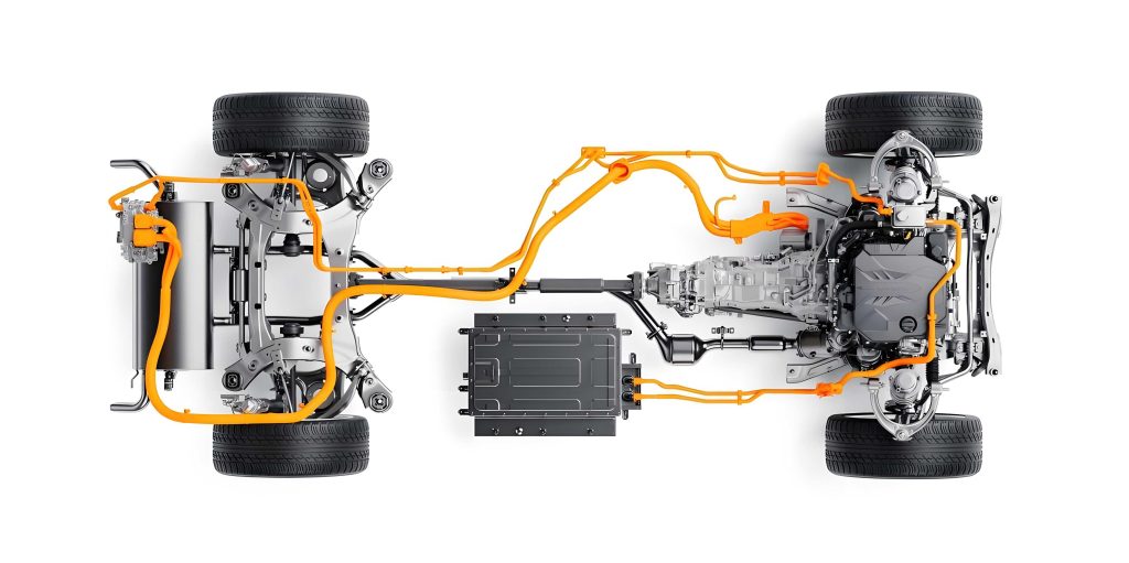
In my extensive career as an automotive diagnostics specialist, I have observed a significant shift towards hybrid electric vehicle technologies. These complex systems integrate internal combustion engines with electric propulsion, creating unique challenges for maintenance and repair. The hybrid electric vehicle represents a pinnacle of modern automotive engineering, but its sophistication demands a deep understanding of both traditional mechanical systems and advanced electronic networks. This article draws from my firsthand experiences to elaborate on systematic diagnostic approaches, focusing on common electrical and powertrain faults, while emphasizing the distinct characteristics of the hybrid electric vehicle platform.
The fundamental architecture of a hybrid electric vehicle can be summarized by its dual power sources. The total drivetrain power ($P_{total}$) is the sum of the power from the internal combustion engine ($P_{ICE}$) and the power from the electric motor-generator ($P_{MG}$). This relationship is expressed as:
$$P_{total} = P_{ICE} + P_{MG} = \tau_{ICE} \cdot \omega_{ICE} + \tau_{MG} \cdot \omega_{MG}$$
where $\tau$ represents torque and $\omega$ represents angular velocity. The energy management system dynamically controls this balance. A failure in any subsystem—be it high-voltage battery management, power inverter control, or low-voltage accessory networks—can lead to performance degradation or complete system shutdown. The following table outlines core components of a typical hybrid electric vehicle and their associated failure modes.
| System Domain | Key Component | Primary Function | Typical Failure Modes & Symptoms |
|---|---|---|---|
| High-Voltage Powertrain | Traction Battery Pack | Stores electrical energy for propulsion | Capacity loss, cell voltage imbalance, thermal runaway |
| Power Inverter Unit (PIU) | Converts DC battery power to AC for motor | IGBT/MOSFET failure, coolant leakage, communication loss | |
| Motor-Generator (MG1/MG2) | Provides traction torque and regenerative braking | Winding short/open circuit, bearing wear, resolver fault | |
| Low-Voltage Systems & Body Electronics | DC-DC Converter | Steps down high-voltage DC to 12V for accessories | Output voltage instability, complete shutdown |
| Body Control Modules & Networks (CAN, LIN) | Manages comfort, convenience, and safety features | Network bus faults, module software corruption, power/ground issues | |
| Thermal Management | Hybrid Power Unit Coolant System | Cools engine, inverter, and battery | Pump failure, thermostat stuck, coolant leakage or degradation |
Diagnosing issues in a hybrid electric vehicle often begins with the low-voltage electrical system, as it controls many ancillary functions. A common entry point is the Local Interconnect Network (LIN), a serial communication protocol widely used for controlling subsystems like power windows, mirrors, and seats. The LIN bus is a single-wire, master-slave network. The voltage waveform on a functional LIN bus is a pulsed digital signal. If a slave node (e.g., a door window switch) is disconnected due to a break in the bus wire, the waveform measured at the slave connector will appear as a constant battery voltage (e.g., 12V), indicating an open circuit. The diagnostic process for such a fault involves systematic measurement of resistance and waveform analysis. The signal integrity on a LIN bus can be modeled by its voltage level $V_{LIN}(t)$, which should alternate between a recessive state (near battery voltage, $V_{Bat}$) and a dominant state (near ground, ~0V). A faulty open circuit presents as:
$$V_{LIN}(t) = V_{Bat} \quad \text{(constant)}$$
Conversely, a healthy waveform shows:
$$V_{LIN}(t) = V_{Bat} – I_{pull-up} \cdot R_{line} \quad \text{(during recessive bits)}$$
$$V_{LIN}(t) \approx 0V \quad \text{(during dominant bits)}$$
where $I_{pull-up}$ is the current through the master’s internal pull-up resistor and $R_{line}$ is the line resistance. This precise understanding is crucial when troubleshooting body electronics in any modern hybrid electric vehicle.
Beyond body electronics, powertrain faults in a hybrid electric vehicle present a higher level of complexity. Take, for instance, a fault code related to turbocharger performance in the internal combustion engine portion of a hybrid system. The turbocharger’s function is to increase engine volumetric efficiency. Its pressure ratio $\Pi_c$ is defined as:
$$\Pi_c = \frac{P_{out}}{P_{in}}$$
where $P_{out}$ is the compressor outlet pressure and $P_{in}$ is the inlet pressure. A malfunctioning wastegate actuator, often controlled by an electronic pressure converter (Y77), can lead to under-boosting. The target boost pressure $P_{boost}^{target}$ is calculated by the Engine Control Unit (ECU) based on driver demand and operating conditions. If the actual measured pressure $P_{boost}^{actual}$ deviates beyond a calibrated threshold $\Delta P_{max}$ for a duration $t$, a fault is logged:
$$\int_{0}^{t} |P_{boost}^{target} – P_{boost}^{actual}| \, dt > \Delta P_{max} \cdot t$$
This integral fault model is common in modern diagnostics. In a hybrid electric vehicle, such an engine fault might be masked or compensated for by the electric motor providing additional torque, but it will eventually trigger a check engine light and store a fault code like P024400. The diagnostic tree for such a code in the context of a hybrid electric vehicle must consider interactions with the hybrid control unit.
| Step | Action | Tool Required | Expected Outcome & Interpretation |
|---|---|---|---|
| 1 | Retrieve all fault codes from Engine Control Unit (ECU), Hybrid Control Unit (HCU), and other relevant modules. | Advanced Diagnostic Scan Tool (e.g., supporting OEM-specific protocols) | Obtain a complete system snapshot. Correlate codes across modules. A code in the HCU may point to a compensating strategy for an engine fault. |
| 2 | Perform active tests (actuator diagnostics) on suspected components (e.g., wastegate actuator, throttle valve, EGR valve). | Diagnostic Scan Tool with bidirectional control | Verify mechanical and electrical response. No movement indicates a faulty actuator, wiring (open/short circuit), or driver circuit within the control unit. |
| 3 | Monitor live data parameters related to the fault (e.g., specified vs. actual boost pressure, MAF sensor readings, fuel trims, electric motor torque contribution). | Diagnostic Scan Tool with data graphing capability | Identify deviations from normative values. In a hybrid electric vehicle, observe if $P_{MG}$ increases to compensate for a drop in $P_{ICE}$. |
| 4 | Check integrity of related sensors and wiring. Measure supply voltage, signal voltage, ground, and check for short circuits to power/ground. | Digital Multimeter (DMM), Oscilloscope | Confirm sensor circuit resistance and signal plausibility. For example, a MAP sensor output should follow $V_{out} = V_{supply} \cdot (P_{actual} / P_{max})$. |
| 5 | Inspect mechanical components for obvious damage, leaks, or restrictions (e.g., intercooler, turbocharger vanes, exhaust system). | Visual and physical inspection, borescope | Identify physical failures causing functional faults. A cracked intercooler hose will leak boost pressure. |
| 6 | Verify control unit software calibration and, if necessary, perform programming/coding updates as per Technical Service Bulletins (TSBs). | Flash programming tool with internet access for latest software | Resolve issues caused by software bugs or incompatibilities, a common necessity in complex hybrid electric vehicle systems. |
The electrical energy storage system is the heart of a hybrid electric vehicle. Its state of health (SOH) and state of charge (SOC) are critical parameters. SOC is typically calculated using a coulomb counting method combined with voltage modeling:
$$SOC(t) = SOC(t_0) – \frac{1}{C_{nominal}} \int_{t_0}^{t} \eta I_{batt}(\tau) \, d\tau$$
where $C_{nominal}$ is the nominal battery capacity, $I_{batt}$ is the battery current (positive for discharge), and $\eta$ is the coulombic efficiency. A failing battery module will exhibit increased internal resistance $R_{internal}$, leading to excessive voltage sag under load according to Ohm’s law: $V_{drop} = I_{batt} \cdot R_{internal}$. This voltage drop reduces available power and can trigger isolation faults. Monitoring the differential voltage $\Delta V$ between individual cells in a series string is essential:
$$\Delta V_{max} = \max(V_{cell,i}) – \min(V_{cell,i}) \quad \text{for } i = 1, 2, …, N$$
If $\Delta V_{max}$ exceeds a threshold (e.g., 0.3V) during charging or discharging, the battery management system (BMS) will likely limit performance to protect the pack, which the driver may perceive as a lack of power or inability to use pure electric mode—a key feature of any hybrid electric vehicle.
Preventive maintenance is paramount for the long-term reliability of a hybrid electric vehicle. Unlike conventional vehicles, maintenance schedules must account for the high-voltage system’s cooling, insulation resistance checks, and software updates. The following table proposes a comprehensive maintenance schedule tailored for a hybrid electric vehicle, integrating traditional and novel requirements.
| Interval (Miles/Km or Months) | Service Items for Internal Combustion Engine | Service Items for Electric Drive & High-Voltage System | Service Items for Chassis & Body Systems |
|---|---|---|---|
| 10,000 km / 12 months | Engine oil and filter change; Inspect air filter, belts, and hoses. | Visual inspection of high-voltage cable connectors and orange wiring for damage; Scan for historical fault codes in HCU and BMS. | Rotate tires; Inspect brake pads, discs, and fluid level; Check operation of all lights and wipers. |
| 30,000 km / 24 months | Replace engine air filter and cabin air filter; Check spark plugs (if applicable). | Perform insulation resistance test on the high-voltage system using a megaohmmeter (e.g., test at 500V DC). Check coolant level and condition for the inverter/battery cooling system. | Inspect suspension components; Lubricate locks and hinges; Test battery (12V) state of health. |
| 60,000 km / 48 months | Replace engine coolant; Inspect fuel system (including injectors on hybrid electric vehicle engines, which may have unique carbon buildup patterns). | Replace inverter/battery cooling system coolant according to OEM specification (often a specific long-life type). Detailed diagnostic scan of all control units for software updates. | Replace brake fluid; Inspect and possibly replace brake pads/discs (wear may be less due to regenerative braking). |
| 100,000 km / 72 months | Comprehensive engine check: compression test, leak-down test, inspect EGR and turbocharger systems. | Professional assessment of high-voltage traction battery State of Health (SOH) using OEM diagnostic tools. Check and torque high-voltage connection points. | Replace shock absorbers if needed; Inspect all body electrical connections and network integrity (CAN/LIN bus health). |
The thermal management system in a hybrid electric vehicle is exceptionally complex, as it must dissipate heat from the engine, power electronics, and the traction battery. The heat load $Q_{total}$ that must be rejected is the sum of contributions from all sources:
$$Q_{total} = Q_{engine} + Q_{inverter} + Q_{battery} + Q_{other}$$
The cooling system’s capacity is defined by the heat transfer equation: $Q = \dot{m} \cdot c_p \cdot \Delta T$, where $\dot{m}$ is the coolant mass flow rate, $c_p$ is the specific heat capacity of the coolant, and $\Delta T$ is the temperature difference across the component. A failure in the electric coolant pump for the hybrid system can lead to rapid overheating of the inverter or battery, causing a severe fault and potentially expensive repairs. Therefore, monitoring pump current draw and coolant temperature sensors is a critical aspect of hybrid electric vehicle diagnostics.
Another fascinating aspect of hybrid electric vehicle technology is regenerative braking. The kinetic energy recovered during deceleration ($E_{regen}$) can be estimated by:
$$E_{regen} = \int_{t_{start}}^{t_{end}} P_{regen}(t) \, dt = \int_{t_{start}}^{t_{end}} \eta_{regen} \cdot \tau_{MG}(t) \cdot \omega_{MG}(t) \, dt$$
where $\eta_{regen}$ is the efficiency of the motor-generator and power electronics during regeneration. A fault in the wheel speed sensors, brake pedal position sensor, or hybrid control unit can disable this function, reducing fuel economy and increasing wear on the friction brakes. Diagnosing such an issue requires analyzing data from the anti-lock braking system (ABS) module, the hybrid control unit, and the engine control unit simultaneously, showcasing the deep integration inherent in a hybrid electric vehicle.
In conclusion, maintaining and repairing a hybrid electric vehicle demands a paradigm shift from traditional automotive practice. The technician must be proficient in high-voltage safety procedures, network communications diagnostics, data-driven analysis, and understand the intricate interplay between the electrical and mechanical powertrains. The two case studies referenced earlier—involving a LIN bus fault affecting a window and a turbocharger wastegate actuator failure—are mere examples of symptoms that can occur within the vast ecosystem of a hybrid electric vehicle. Each diagnosis requires a methodical approach, leveraging tools like oscilloscopes for waveform analysis, scan tools for bidirectional control, and multimeters for circuit testing. As the prevalence of the hybrid electric vehicle continues to grow, the industry’s knowledge base and toolset must evolve accordingly. Future advancements in onboard diagnostics (OBD) for hybrid and electric vehicles will likely provide even deeper insights, but the fundamental principles of electrical theory, logical fault tracing, and systematic verification will remain the cornerstone of effective repair. The hybrid electric vehicle is not just a car with an extra battery; it is a seamlessly integrated electromechanical system that offers superior efficiency and performance, and its care requires an equally integrated and knowledgeable approach from service professionals.