
With the increasing global awareness of environmental protection, electric vehicles have become a vital component in the transportation sector. In this context, EV charging stations, as essential supporting infrastructure, have gained significant importance in their construction and operation. However, traditional fixed EV charging stations face challenges such as high construction costs, poor layout flexibility, and an inability to meet diverse site and user requirements. Mobile EV charging stations, as a flexible and efficient solution, demonstrate superior adaptability and service capabilities, addressing a wide range of charging needs. Based on this, we designed a mobile EV charging station and optimized its structure using Workbench. By leveraging scientific and rational structural design principles, along with advanced 3D modeling tools and finite element analysis software, we gained deeper insights into the dimensional changes of the mobile EV charging station under three working conditions. The results show that the optimized mobile EV charging station achieves improvements in mass, cost, and material usage efficiency.
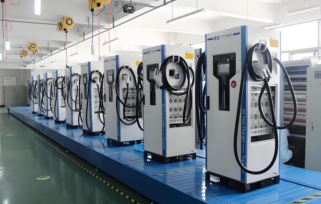
The structural design of the mobile EV charging station includes components such as the support frame, charging bracket, charging cable, charger, charging baffle, external charging panel, charging interface, and charging panel. The mobile EV charging station features a rectangular box-shaped exterior, equipped with a charging interface and charging panel. Additionally, the housing of the EV charging station includes mounting holes for easy installation in various locations.
The charging interface of the mobile EV charging station is a contact-based interface. Its working principle involves first controlling the rectifier to convert alternating current from the cable into direct current, which is stored in the battery of the mobile EV charging station. During charging, the mobile EV charging station inverts the stored direct current back to alternating current, which is then transmitted to the electric vehicle through the charging interface to complete the charging process. Due to its mobility and versatility, this EV charging station can be flexibly installed in various locations, facilitating quick setup and disassembly in different scenarios.
Optimization Analysis Methods for Mobile EV Charging Stations
ANSYS/Workbench is a general-purpose finite element analysis software developed by ANSYS Inc. This software integrates finite element analysis methods with relevant tools and serves as an excellent computer-aided engineering (CAE) platform, enabling the creation of a collaborative simulation environment. During product development and manufacturing, the software consolidates data, models, and technologies into a single simulation environment. This integrated environment encompasses 3D modeling, finite element model creation, computational simulation, and data analysis, providing comprehensive simulation and analysis services. Consequently, engineers and designers can better predict product behavior and optimize designs in the early stages of development.
Structural Design Optimization
For the mobile EV charging station, we employed finite element analysis methods to ensure design flexibility. Finite element analysis involves modeling, meshing, applying loads, and solving for the mobile EV charging station using ANSYS/Workbench. Since both the EV charging station and the onboard charger are electromechanical devices, the optimization module of ANSYS/Workbench software was used to optimize the structural parameters of the mobile EV charging station.
Optimizing the structural design requires综合考虑 the geometric shape and functional requirements of the EV charging station. Using the optimization module of ANSYS/Workbench software, we optimized the structural parameters of the EV charging station and then incorporated the optimized results into the charging station components for finite element analysis, ultimately obtaining the deformation behavior of the EV charging station. Furthermore, the finite element analysis results were combined with the design parameters of the mobile EV charging station, and adjustments were made to the structure based on simulation outcomes to achieve a mobile EV charging station structure that meets functional requirements.
Structural Reliability Analysis
In structural analysis, uncertainties such as material properties, boundary conditions, and manufacturing tolerances exist. To analyze the impact of these factors on the structure, they are typically set as deterministic parameters during modeling. Although precise values of these parameters are difficult to determine in practical applications, by combining probabilistic assessment methods, the failure probability can be accurately predicted without relying on fixed values. Reliability analysis has become an important tool for calculating the safety of mobile EV charging stations under the influence of uncertain factors and the probability of the mobile EV charging station achieving its intended functions.
With the continuous development of reliability analysis techniques, many mature and widely used reliability analysis methods have emerged. Among them, the Monte Carlo method is a common approach. The Monte Carlo method uses numerical simulation to solve complex structural reliability problems and is also known as the statistical试验法 or random sampling method. Its theoretical basis lies in probability theory and mathematical statistics, where specific methods are used to obtain random numbers and random variables \( x_i \), which are then substituted into the performance function \( g(x) \) to obtain a function value. If \( g(x) \leq 0 \), it indicates structural failure, and a failure event is recorded in the program; if \( g(x) > 0 \), it indicates the structure is safe, and no record is made. After one calculation, a random number is obtained, and the process continues until the desired number of experiments is reached. Finally, the experimental results are statistically processed to obtain the failure probability \( p_f \):
$$p_f = p[g(x) \leq 0] = \lim_{n \to \infty} \frac{k}{n}$$
where \( p_f \) is the failure probability of reliability, \( p[g(x) \leq 0] \) is the sampling distribution probability, \( n \) is the total number of sampling simulations, and \( k \) is the total number of qualified instances where \( g(x) \geq 0 \).
Analysis shows that the failure probability is related to the total number of sampling simulations \( n \), and the calculation results become more accurate as \( n \) increases.
Optimization Model for Mobile EV Charging Station Based on Workbench
The finite element method, as a numerical求解 approach, discretizes complex physical problems into small finite elements and establishes connections between these elements. By performing discrete processing on each element and constructing an analysis model for finite element analysis, the numerical solution of the original physical problem can be obtained.
3D Modeling
The finite element method is widely applied, especially in modern lightweight design, where numerical求解 methods play an increasingly important role in structural optimization design. When using the finite element method for structural analysis, a solid foundation in elastic mechanics is essential, and familiarity with the five basic assumptions is necessary to better apply these assumptions for analysis: 1) Continuity assumption, which assumes the structure under study is continuous, with no defects or gaps between materials; forces and displacements are transmitted through element nodes and can be represented by functions. 2) Homogeneity assumption, which assumes the material under study is uniformly distributed, with no variation in properties due to location. 3) Isotropy assumption, which assumes the material’s properties are the same in all directions, facilitating unified parameters. 4) Linear elasticity assumption, which assumes the displacement of the structure has a linear relationship with external loads. 5) Small deformation assumption, which assumes the deformation of the structure is small compared to its own dimensions.
Referring to the CAD drawings of the mobile EV charging station and实体 diagrams, we used UG NX10.0 modeling software to simplify the structure and create a 3D model of the EV charging station. Finite element models often employ three types of elements: beam elements, solid elements, and shell elements. The advantage of beam element calculations is simple pre-processing and fast computation speed, but the accuracy is lower; solid element calculations offer the highest accuracy, but the large number of element nodes results in heavy computational workload and low efficiency; shell elements are commonly used in thin plate structures,能够反映 the true mechanical performance of the frame, and have thickness properties, facilitating subsequent size optimization design. Based on comprehensive considerations, we adopted shell elements for finite element simulation. The simplified structural model of the EV charging station frame is as follows.
Mesh Generation
In UG software, the 3D solid model of the EV charging station was exported in STEP format and then imported into Hypermesh Mesh for mesh generation. Hypermesh software has powerful mesh generation capabilities and offers a variety of functions. Flexibly using Hypermesh Mesh’s surface mesh, solid mesh, and 1D mesh, complex structures can be meshed. Additionally, Hypermesh Mesh software has good compatibility and can work with common solvers, making it convenient to operate. After importing the EV charging station model into Hypermesh Mesh, a solver needs to be selected. Since the finite element simulation is performed in Workbench, the Workbench solver was chosen. Given the complexity of the model, geometric information loss may occur during import, so model repair is required. Due to the large size of the EV charging station model, after comparative calculations, the main load-bearing structures such as the upper panel, left panel, lower panel, and right panel were meshed with a size of 10 mm, while the remaining parts, being auxiliary structures, do not require high precision and were meshed with a size of 15 mm. After meshing, there are a total of 156,086 cells and 168,136 nodes.
Optimization Analysis of Panel Thickness
Through the software operation panel, the thickness of the upper panel, left panel, and lower panel can be adjusted to meet different usage requirements. The thickness variation range for the upper panel is 5–8 mm, for the left panel is 3–5 mm, and for the lower panel is 6–10 mm. Using the mechanical analysis module in Workbench, based on the mechanical conditions of the working conditions, the minimum mass was selected as the objective function. The thickness of the panels under three working conditions was optimized, and the stress results after optimization were obtained, as shown in Tables 1 and 2, to better analyze and evaluate the mechanical performance of the EV charging station.
| Working Condition | Upper Panel Thickness (mm) | Left Panel Thickness (mm) | Lower Panel Thickness (mm) |
|---|---|---|---|
| Initial State | 8.00 | 5.00 | 10.00 |
| Bending Condition | 5.09 | 3.67 | 6.98 |
| Torsion Condition | 5.35 | 4.21 | 7.53 |
| Unloading Condition | 5.03 | 3.98 | 7.22 |
| Actual State | 6.00 | 5.00 | 8.00 |
| Working Condition | Yield Limit (MPa) | Maximum Stress Value (MPa) | Maximum Displacement (mm) | Safety Factor |
|---|---|---|---|---|
| Bending Condition | 700 | 378.13 | 2.51 | 1.85 |
| Torsion Condition | 700 | 377.10 | 6.69 | 1.86 |
| Unloading Condition | 700 | 369.94 | 2.50 | 1.89 |
To improve the overall mass of the mobile EV charging station, optimization analysis was conducted under the premise of ensuring the strength, stiffness, and stability of the EV charging station. For the overall mass of the EV charging station, without adding additional components, the upper panel thickness was reduced from 8 mm to 6 mm, a size change rate of 25%. The lower panel thickness was reduced from 10 mm to 8 mm, a size change rate of 20%, while the left panel thickness remained unchanged. After remodeling, the mass of the EV charging station decreased from the original 272.33 kg to 140.67 kg, demonstrating significant optimization效果 and further reducing costs.
Conclusion
This study provides a valuable reference for the engineering practice of EV charging stations, showcasing an integrated approach of technology and design, and pointing out future research directions for mobile EV charging stations. The design combines practicality and feasibility, enriching the research content in the field of electric vehicle charging infrastructure and contributing innovative solutions to the construction of a sustainable transportation system. The optimization of the mobile EV charging station using Workbench has proven effective in achieving lightweight goals and cost reduction, which is crucial for the widespread adoption of EV charging stations. Future work could focus on dynamic load analysis and multi-objective optimization to further enhance the performance of mobile EV charging stations.
In summary, the structural optimization of the mobile EV charging station through finite element analysis and reliability methods has led to significant improvements. The use of advanced CAE tools like Workbench ensures that the EV charging station meets rigorous standards while maintaining flexibility and efficiency. As the demand for electric vehicles grows, the development of optimized mobile EV charging stations will play a pivotal role in supporting sustainable mobility solutions.