
As we navigate the transformative era of sustainable transportation, the electric drive system stands at the forefront of innovation, driving the evolution of vehicles from traditional internal combustion engines to efficient, zero-emission platforms. In this comprehensive discussion, I will delve into the latest advancements in electric drive systems, along with complementary technologies such as fuel cells and advanced sensors, which collectively enhance the performance, efficiency, and safety of modern electric vehicles. Our focus will be on elucidating the technical intricacies, supported by tables and formulas, to provide a detailed understanding of these cutting-edge developments. Throughout this article, the term “electric drive system” will be emphasized repeatedly to underscore its pivotal role in the automotive industry’s future.
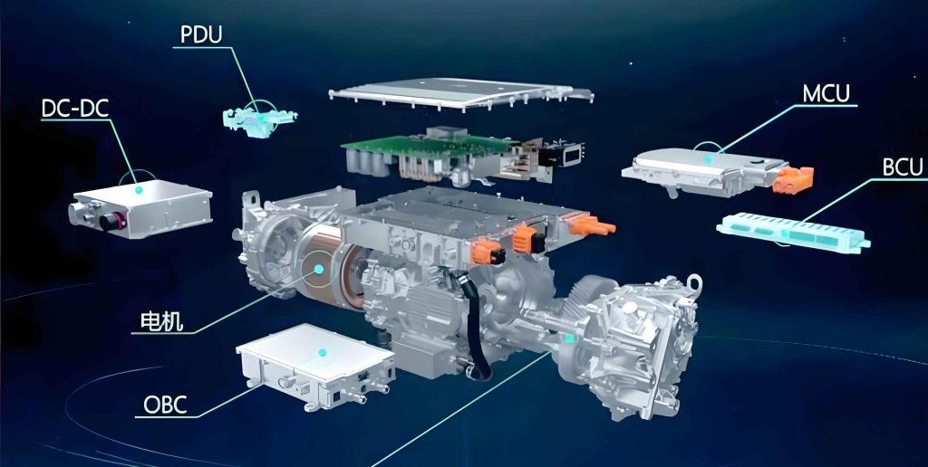
The electric drive system is the heart of any electric vehicle, converting electrical energy into mechanical motion to propel the vehicle. In our recent endeavors, we have developed a central electric drive system based on a “plug-and-play” design philosophy. This system is engineered for seamless integration into existing vehicle platforms, minimizing modifications to the chassis, axles, or differentials. By enabling manufacturers to transform conventional models into electric variants with minimal effort, this electric drive system optimizes costs and accelerates the adoption of electrification. The core components include a central electric drive unit, motor controller, and drive force controller, all supplied as a complete package to offer holistic solutions for application, performance, efficiency, and longevity.
To quantify the performance of our electric drive system, we can express the output torque as a function of current and motor constants. For instance, the maximum system output torque reaches 3200 Nm, which is applicable to city buses, coaches, and even electric trucks. The efficiency of the electric drive system can be modeled using the following formula:
$$ \eta_{\text{drive}} = \frac{P_{\text{mech}}}{P_{\text{elec}}} = \frac{T \cdot \omega}{V \cdot I} $$
where \( \eta_{\text{drive}} \) is the efficiency of the electric drive system, \( T \) is the torque in Nm, \( \omega \) is the angular velocity in rad/s, \( V \) is the voltage, and \( I \) is the current. This equation highlights how optimizing these parameters enhances the overall effectiveness of the electric drive system. Moreover, the power output can be derived as:
$$ P_{\text{out}} = T \cdot \omega = k_t \cdot I \cdot \omega $$
with \( k_t \) representing the torque constant. These formulas underscore the importance of precise control in maximizing the performance of the electric drive system.
In addition to the central electric drive system, we have explored advancements in fuel cell technology, which complements electric drive systems by providing an alternative energy source for electric vehicles. Fuel cells generate electricity through the chemical reaction of hydrogen and oxygen, producing only water as a byproduct. A key component in fuel cells is the metal bipolar plate, which we have developed leveraging expertise in materials science, forming technology, and surface treatment. These plates are crucial for stacking into the core stack of a fuel cell system, facilitating efficient energy conversion. The reaction in a proton exchange membrane fuel cell can be summarized as:
$$ 2H_2 + O_2 \rightarrow 2H_2O + \text{electrical energy} + \text{heat} $$
The overall efficiency of a fuel cell system, when integrated with an electric drive system, can be expressed as:
$$ \eta_{\text{total}} = \eta_{\text{fuel cell}} \cdot \eta_{\text{electric drive system}} $$
where \( \eta_{\text{fuel cell}} \) is the fuel cell efficiency, typically around 40-60%, and \( \eta_{\text{electric drive system}} \) is as defined earlier. This synergy highlights how fuel cells can enhance the range and sustainability of vehicles powered by electric drive systems.
To further illustrate the components of our electric drive system and related technologies, the following table provides a detailed breakdown:
| Component | Function | Key Parameters | Application in Electric Drive System |
|---|---|---|---|
| Central Electric Drive Unit | Converts electrical energy to mechanical torque | Max torque: 3200 Nm, Speed range: 0-5000 rpm | Core of the electric drive system for propulsion |
| Motor Controller | Regulates current and voltage to the motor | Efficiency: >95%, Switching frequency: 10 kHz | Ensures optimal performance of the electric drive system |
| Drive Force Controller | Manages torque distribution and vehicle dynamics | Response time: < 5 ms, Integration with CAN bus | Enhances stability and control in the electric drive system |
| Metal Bipolar Plates | Facilitates fuel cell reactions and current collection | Thickness: 0.1 mm, Coating: graphene-based | Supports fuel cell systems that may power electric drive systems |
| Solid-State 3D Flash LiDAR | Provides high-resolution 3D environmental mapping | Range: up to 200 m, Field of view: 120°, Frame rate: 25 Hz | Augments safety and autonomy in vehicles with electric drive systems |
Another critical area of innovation is in sensor technology, particularly for autonomous driving, which enhances the functionality of vehicles equipped with electric drive systems. We have developed a solid-state 3D flash LiDAR sensor designed for commercial vehicle markets. This sensor offers superior angular resolution and accuracy in dense urban environments, complementing existing ADAS suites. Unlike traditional radar, it emits laser pulses in non-visible wavelengths, ensuring eye safety. The distance measurement principle of LiDAR can be described by:
$$ d = \frac{c \cdot \Delta t}{2} $$
where \( d \) is the distance to an object, \( c \) is the speed of light (approximately \( 3 \times 10^8 \) m/s), and \( \Delta t \) is the time delay between pulse emission and detection. This sensor captures 4096 continuous depth data pixels per frame, generating detailed 3D point clouds that define and track moving objects. When integrated with an electric drive system, such sensors enable precise navigation and collision avoidance, crucial for autonomous electric vehicles.
The integration of these technologies into a cohesive ecosystem is essential for advancing sustainable mobility. For instance, the electric drive system benefits from fuel cells by extending range without compromising zero-emission goals, while advanced sensors like LiDAR improve safety and efficiency. To quantify the interplay, consider the overall energy management in an electric vehicle. The total energy consumption \( E_{\text{total}} \) can be modeled as:
$$ E_{\text{total}} = \int (P_{\text{drive}} + P_{\text{aux}}) \, dt $$
where \( P_{\text{drive}} \) is the power required by the electric drive system, and \( P_{\text{aux}} \) includes auxiliary systems like sensors and climate control. Optimizing this equation through efficient components reduces energy waste, thereby enhancing the sustainability of the electric drive system.
We have also focused on thermal management within the electric drive system, as overheating can degrade performance and longevity. The heat generation in an electric motor can be approximated by:
$$ Q = I^2 R t $$
where \( Q \) is the heat generated in joules, \( I \) is the current, \( R \) is the resistance, and \( t \) is time. Effective cooling systems, such as liquid cooling, are integrated into our electric drive system to dissipate this heat, ensuring reliable operation. Additionally, in fuel cell systems, thermal management modules regulate temperatures to maintain optimal reaction rates, further supporting the electric drive system when used in hybrid configurations.
To provide a comparative analysis of different electric drive system configurations, the following table outlines key performance metrics:
| Configuration | Efficiency (%) | Max Torque (Nm) | Weight (kg) | Integration Complexity | Suitability for Electric Drive System |
|---|---|---|---|---|---|
| Central Electric Drive | 92-95 | 3200 | 150 | Low (plug-and-play) | High for buses and trucks |
| Distributed Wheel Hub Motors | 88-92 | 800 per wheel | 200 (total) | Moderate (requires chassis mods) | Medium for lightweight vehicles |
| Fuel Cell Hybrid System | 50-60 (fuel cell) + 90-95 (electric drive) | 3000 | 300 | High (complex integration) | High for long-range applications |
| Battery-Electric with LiDAR | 90-94 | 2500 | 180 | Low to moderate | High for autonomous urban transport |
The development of these technologies is driven by the need for cost optimization and scalability. For the electric drive system, we employ modular designs that allow for mass production, reducing unit costs. The cost function \( C_{\text{drive}} \) for manufacturing an electric drive system can be expressed as:
$$ C_{\text{drive}} = C_{\text{materials}} + C_{\text{labor}} + C_{\text{overhead}} $$
where each component is minimized through automation and efficient supply chains. Similarly, for fuel cell bipolar plates, advanced coating techniques reduce material costs while enhancing durability, indirectly benefiting the electric drive system by lowering overall vehicle expenses.
In terms of control algorithms, the electric drive system relies on sophisticated software to manage torque vectoring and energy regeneration. The control law for torque output can be derived from PID controllers:
$$ T_{\text{out}} = K_p e(t) + K_i \int e(t) \, dt + K_d \frac{de(t)}{dt} $$
where \( e(t) \) is the error between desired and actual torque, and \( K_p \), \( K_i \), \( K_d \) are tuning constants. This ensures smooth and responsive performance of the electric drive system under varying load conditions. Moreover, in autonomous vehicles, sensor fusion algorithms combine LiDAR data with camera and radar inputs to create a comprehensive environmental model, enhancing the decision-making processes that interact with the electric drive system.
Looking ahead, the evolution of the electric drive system will be influenced by advancements in battery technology, power electronics, and regulatory frameworks. For example, higher energy-density batteries will reduce the weight and size of energy storage units, directly impacting the design of the electric drive system. The relationship between battery capacity \( C_{\text{batt}} \) and driving range \( R \) can be modeled as:
$$ R = \frac{C_{\text{batt}} \cdot V_{\text{batt}}}{\rho_{\text{vehicle}}} $$
where \( V_{\text{batt}} \) is the battery voltage, and \( \rho_{\text{vehicle}} \) is the vehicle’s energy consumption per kilometer. As batteries improve, the electric drive system can be optimized for higher efficiency and lower costs.
Furthermore, standardization efforts are crucial for interoperability of electric drive systems across different vehicle platforms. We advocate for common interfaces and communication protocols, such as CAN FD or Ethernet, to facilitate seamless integration. The benefits of standardization can be quantified through reduced development time \( \Delta t_{\text{dev}} \):
$$ \Delta t_{\text{dev}} = t_{\text{custom}} – t_{\text{standard}} $$
where \( t_{\text{custom}} \) and \( t_{\text{standard}} \) are development times for custom and standardized electric drive systems, respectively. This accelerates time-to-market for manufacturers adopting our electric drive system.
In conclusion, the electric drive system is a cornerstone of modern sustainable transportation, and its continuous improvement is vital for achieving global emission targets. Through innovations in central drive units, fuel cell components, and advanced sensors, we are pushing the boundaries of what is possible with electric drive systems. The integration of these technologies not only enhances performance but also paves the way for fully autonomous, zero-emission vehicles. As we move forward, our commitment to refining the electric drive system remains unwavering, driven by the goal of creating a cleaner, safer, and more efficient mobility ecosystem.
To encapsulate the technical details discussed, here is a summary table of key formulas related to the electric drive system and associated technologies:
| Formula Description | LaTeX Representation | Application Context |
|---|---|---|
| Efficiency of electric drive system | $$ \eta_{\text{drive}} = \frac{T \cdot \omega}{V \cdot I} $$ | Evaluating performance of the electric drive system |
| Fuel cell reaction | $$ 2H_2 + O_2 \rightarrow 2H_2O + \text{energy} $$ | Energy generation for hybrid electric drive systems |
| LiDAR distance measurement | $$ d = \frac{c \cdot \Delta t}{2} $$ | Sensor integration with electric drive system for autonomy |
| Heat generation in motor | $$ Q = I^2 R t $$ | Thermal management in the electric drive system |
| Total energy consumption | $$ E_{\text{total}} = \int (P_{\text{drive}} + P_{\text{aux}}) \, dt $$ | System-level optimization of electric drive system |
| Torque control via PID | $$ T_{\text{out}} = K_p e(t) + K_i \int e(t) \, dt + K_d \frac{de(t)}{dt} $$ | Control algorithms for the electric drive system |
The journey toward electrified mobility is multifaceted, and the electric drive system serves as the linchpin that connects various technological strands. By relentlessly innovating in this domain, we aim to deliver solutions that are not only technically superior but also economically viable and environmentally responsible. The electric drive system, in its myriad forms, will continue to evolve, shaping the future of transportation for generations to come.