
As environmental awareness grows and technology advances, new energy vehicles (NEVs) have rapidly developed worldwide. As a core component of NEVs, the electronic control system (ECS) directly impacts vehicle safety and operational efficiency. Its stability and reliability are crucial, yet the complexity of the ECS presents significant challenges for fault diagnosis and maintenance. In this study, I delve into the intricacies of NEV ECS fault diagnosis and repair strategies, aiming to enhance road safety and vehicle performance. Through first-person exploration, I will discuss system components, diagnostic techniques, and maintenance protocols, incorporating tables and formulas to summarize key concepts. The term ‘motor control unit’ will be frequently emphasized, as it plays a pivotal role in the ECS.
The ECS in NEVs is a highly integrated and complex system, primarily comprising the battery management system (BMS), motor control unit (MCU), and vehicle control unit (VCU). These components are interconnected via high-speed data communication buses, enabling real-time information sharing and协同工作. For instance, the BMS monitors parameters like voltage, current, and temperature of each battery cell, optimizing charge-discharge cycles to extend battery life. The motor control unit, a key executive component, adjusts torque and speed based on commands from the VCU, ensuring smooth acceleration and deceleration. The VCU acts as a command center, processing sensor data to manage energy, diagnose faults, and facilitate network communication. To illustrate, consider a simplified model of battery dynamics: the state of charge (SOC) can be estimated using the coulomb counting method, expressed as $$SOC(t) = SOC_0 – \frac{1}{Q_n} \int_0^t i(\tau) d\tau$$, where \(SOC_0\) is the initial SOC, \(Q_n\) is the nominal capacity, and \(i(t)\) is the current. Similarly, the motor control unit operates based on torque control equations, such as $$T_e = k_t \cdot i_q$$, where \(T_e\) is the electromagnetic torque, \(k_t\) is the torque constant, and \(i_q\) is the quadrature-axis current. These formulas highlight the technical depth involved in ECS operations.
| Component | Primary Function | Key Parameters Monitored |
|---|---|---|
| Battery Management System (BMS) | Monitor battery state, prevent overcharge/over-discharge | Voltage, current, temperature, SOC |
| Motor Control Unit (MCU) | Control motor torque and speed based on VCU commands | Torque, speed, current, voltage |
| Vehicle Control Unit (VCU) | Coordinate overall vehicle functions, diagnose faults | Speed, brake pressure, steering angle, energy flow |
In my analysis, fault diagnosis techniques are essential for maintaining ECS integrity. Electronic diagnosis technology utilizes specialized instruments to monitor real-time performance indicators, enabling precise fault localization. For example, by analyzing data streams,维修人员 can identify anomalies in the motor control unit, such as irregular current spikes. This technology relies on algorithms like fault detection and isolation (FDI), which can be modeled as $$y(t) = f(x(t), \theta) + e(t)$$, where \(y(t)\) is the measured output, \(x(t)\) is the state vector, \(\theta\) represents parameters, and \(e(t)\) is the error term indicating faults. Another prevalent method is fault code diagnosis technology, which interprets diagnostic trouble codes (DTCs) generated by the ECS. These codes provide clues about fault locations, such as a P0A1F code indicating a motor control unit malfunction. I often employ this in practice by connecting a scan tool to the onboard diagnostics (OBD) port, reading codes like U0100 for communication loss with the motor control unit. To compare these techniques, I have compiled a table below.
| Technology | Principle | Advantages | Limitations |
|---|---|---|---|
| Electronic Diagnosis | Real-time monitoring and data analysis using instruments | High accuracy, immediate fault detection | Requires expensive equipment, skilled operators |
| Fault Code Diagnosis | Interpretation of DTCs from ECS modules | Quick identification, standardized codes | May miss intermittent faults, dependent on code accuracy |
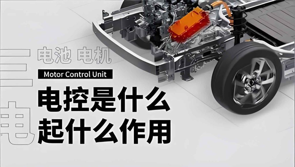
Regarding the motor control unit, it is a critical subsystem that demands focused attention. The motor control unit regulates the electric motor’s performance, and its failure can lead to reduced efficiency or complete breakdown. In my experience, common issues include overheating due to excessive current, modeled by $$P_{loss} = I^2 R + k_f \omega^2$$, where \(P_{loss}\) is power loss, \(I\) is current, \(R\) is resistance, \(k_f\) is a friction coefficient, and \(\omega\) is angular speed. To visualize its importance, I include an image below that highlights the motor control unit’s role in the ECS architecture.
Maintenance strategies are equally vital to ensure long-term ECS reliability. I advocate for standardized repair操作流程 to minimize human error. This involves steps like pre-repair diagnostics, adherence to safety protocols, and post-repair testing. For instance, when servicing the motor control unit, I follow a checklist: first, verify input voltages using a multimeter, with acceptable ranges defined by $$V_{in} = 12V \pm 10\%$$; second, inspect connections for corrosion; third, update firmware if needed. A comprehensive testing phase post-repair is crucial, involving functional tests of the BMS, MCU, and VCU. I often use formulas to validate performance, such as calculating motor efficiency as $$\eta_m = \frac{P_{out}}{P_{in}} \times 100\%$$, where \(P_{out}\) is mechanical power output and \(P_{in}\) is electrical power input. Expected values should exceed 90% for optimal operation. Additionally, I emphasize经验总结 and sharing within维修团队 to foster continuous improvement. By documenting cases, like a recurrent motor control unit fault due to voltage surges, we develop predictive models, such as $$R_{fail}(t) = \lambda e^{-\lambda t}$$ for failure rate over time \(t\), with \(\lambda\) as the failure rate constant.
| Step | Action | Tools Required | Expected Outcome |
|---|---|---|---|
| 1. Initial Diagnosis | Read DTCs, perform electronic scans | Scan tool, oscilloscope | Identify fault location (e.g., motor control unit) |
| 2. Repair Execution | Replace or repair faulty components | Multimeter, soldering iron | Restore component functionality |
| 3. Post-Repair Test | Conduct functional and road tests | Dynamometer, data logger | Verify system stability and safety |
To deepen the discussion, I explore advanced diagnostic algorithms that integrate with the motor control unit. For example, model-based fault diagnosis uses observers to estimate system states, with residuals calculated as $$r(t) = y(t) – \hat{y}(t)$$, where \(\hat{y}(t)\) is the estimated output. If \(|r(t)|\) exceeds a threshold, a fault is flagged in the motor control unit. Another approach involves machine learning, where neural networks classify faults based on historical data from the motor control unit. The training process minimizes a loss function like $$L = \frac{1}{N} \sum_{i=1}^N (y_i – \hat{y}_i)^2$$, where \(N\) is the number of samples. These techniques enhance the accuracy of diagnosing complex issues, such as subtle degradations in the motor control unit’s performance over time.
In terms of maintenance, I recommend proactive strategies beyond reactive repairs. For the motor control unit,定期保养 includes thermal management checks, as overheating can be predicted using $$T(t) = T_0 + \int_0^t \frac{P_{loss}}{C} dt$$, where \(T(t)\) is temperature, \(T_0\) is initial temperature, and \(C\) is heat capacity. By monitoring this, we can schedule maintenance before failures occur. Furthermore, I stress the importance of software updates for the motor control unit, as firmware bugs can cause erratic behavior. Validation tests post-update should involve simulating driving cycles, with power consumption computed as $$E = \int V(t) I(t) dt$$ to ensure efficiency gains.
Looking ahead, the evolution of NEV ECS will demand更高级的诊断和维修方法. I anticipate increased integration of artificial intelligence for real-time fault prediction in the motor control unit, using algorithms like support vector machines (SVMs) with kernel functions $$K(x_i, x_j) = \exp(-\gamma ||x_i – x_j||^2)$$ for non-linear classification. Additionally, blockchain technology could secure维修记录, enhancing transparency. As I continue my research, I focus on developing standardized protocols that prioritize the motor control unit’s resilience, contributing to safer and more efficient NEVs. In conclusion, through diligent application of diagnostic technologies and maintenance strategies, we can ensure the reliability of NEV electronic control systems, paving the way for sustainable transportation.
To summarize key points, I provide a formula-based overview of ECS health metrics. For instance, overall system reliability can be expressed as $$R_{system}(t) = R_{BMS}(t) \cdot R_{MCU}(t) \cdot R_{VCU}(t)$$, where each component’s reliability \(R(t)\) follows an exponential distribution. This underscores the interdependence of parts like the motor control unit. By embracing innovation and collaboration, we can overcome challenges and advance the NEV industry forward.