
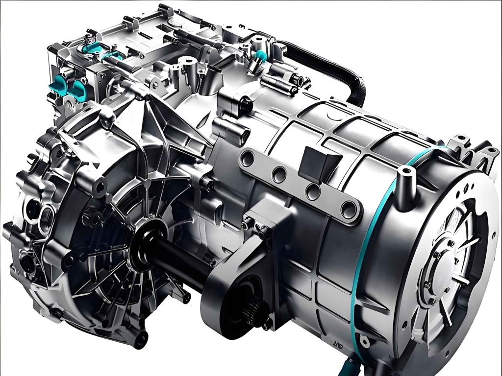
The electric drive unit (EDU) serves as the pivotal core component in new energy vehicles, functioning as the primary actuator that governs vehicle operation. Its control characteristics fundamentally determine the key performance metrics of the electric vehicle. Within the compact architecture of the electric drive unit, the Insulated Gate Bipolar Transistor (IGBT) power modules exhibit substantial thermal dissipation. The high heat flux necessitates an efficient cooling system where coolant is circulated through dedicated internal passages to maintain the IGBT modules within their safe operational temperature window. The integrity of this cooling loop is paramount; a failure in coolant transport due to leakage or connection failure can lead to inadequate heat dissipation, resulting in IGBT overheating, malfunction of the electric drive unit, potential vehicle immobilization, and serious safety hazards.
A critical juncture in this cooling circuit is the connection between the metal coolant pipe and the housing of the electric drive unit. The prevalent method for establishing this connection is an interference fit, also known as a press-fit or shrink-fit. This technique relies on joining components by pressing a pipe (the “inner member” or “shaft”) with a slightly larger outer diameter into a housing bore (the “outer member” or “hub”) with a slightly smaller inner diameter. The dimensional difference, known as the interference, generates significant radial contact pressure at the interface. This pressure, in turn, creates frictional forces that resist axial pull-out (tension) and torsional loads, securing the connection and ensuring sealing performance. Therefore, the reliability of the entire electric drive unit’s thermal management system is intrinsically linked to the mechanical integrity of this press-fit joint, which is predominantly governed by the selected interference magnitude.
Selecting the optimal interference value is a delicate balance. Insufficient interference leads to inadequate contact pressure, resulting in low pull-out force and a risk of leakage or disconnection under operational vibration and thermal cycles. Conversely, excessive interference can induce plastic deformation in one or both components, potentially damaging the electric drive unit housing, altering the material properties, and, paradoxically, reducing the joint strength while also making assembly difficult. This paper presents a comprehensive study on determining the optimal interference fit for the coolant pipe connection in an electric drive unit, integrating theoretical calculation, finite element analysis (FEA), and experimental validation.
Theoretical Foundation of Interference Fits
The mechanical principle of an interference fit is based on the theory of thick-walled cylinders under internal and external pressure. When assembled, the contact pressure \( p_c \) generated at the nominal interface diameter \( d_f \) is the fundamental parameter. The maximum allowable contact pressure is limited by the yield strengths of the materials to prevent permanent deformation. For the outer member (housing, typically aluminum alloy ADC 12) and the inner member (pipe, typically stainless steel SUS 304), the maximum elastic contact pressures are given by:
For the outer member (housing):
$$ p_{c,max,o} = \frac{\sigma_{y,o}}{\sqrt{3}} \cdot \frac{1 – Q_o^2}{\sqrt{3 + Q_o^4}} $$
where \( Q_o = d_i / d_o \) is the diameter ratio for the housing, \( d_i \) is the inner diameter of the housing, \( d_o \) is the outer diameter of the housing, and \( \sigma_{y,o} \) is the yield strength of the housing material.
For the inner member (pipe):
$$ p_{c,max,i} = \frac{\sigma_{y,i}}{2} \cdot (1 – Q_i^2) $$
where \( Q_i = d_i’ / d_f \) is the diameter ratio for the pipe (often approximated for a solid or thick-walled shaft), \( d_i’ \) is the inner diameter of the pipe, and \( \sigma_{y,i} \) is the yield strength of the pipe material.
The overall maximum allowable contact pressure \( p_{c,max} \) is the lower of these two values:
$$ p_{c,max} = \min(p_{c,max,o}, p_{c,max,i}) $$
The required minimum contact pressure \( p_{c,min} \) is dictated by the service loads the joint must transmit—namely, the axial force \( F_a \) (pull-out force from hose connection and pressure) and the torque \( T \) (from potential twisting during assembly or operation). The required pressure is derived from the friction grip needed to resist the combined load:
$$ p_{c,min} = \frac{\sqrt{F_a^2 + \left( \frac{2T}{d_f} \right)^2}}{\pi d_f L_f \mu} $$
where \( L_f \) is the length of the engagement (press-fit length) and \( \mu \) is the static coefficient of friction at the interface.
The interference \( \delta \) required to generate a specific contact pressure \( p_c \) is derived from Lamé’s equations for radial displacement. The total mechanical interference needed is:
$$ \delta = p_c d_f \left( \frac{C_o}{E_o} + \frac{C_i}{E_i} \right) $$
where:
$$ C_o = \frac{1 + Q_o^2}{1 – Q_o^2} + \nu_o, \quad C_i = \frac{1 + Q_i^2}{1 – Q_i^2} – \nu_i $$
\( E_o, E_i \) are the Young’s moduli, and \( \nu_o, \nu_i \) are the Poisson’s ratios of the housing and pipe materials, respectively.
Therefore, the allowable range for the design interference is bounded by:
$$ \delta_{min} = p_{c,min} d_f \left( \frac{C_o}{E_o} + \frac{C_i}{E_i} \right) $$
$$ \delta_{max} = p_{c,max} d_f \left( \frac{C_o}{E_o} + \frac{C_i}{E_i} \right) $$
The design interference \( \delta_{design} \) must satisfy \( \delta_{min} \leq \delta_{design} \leq \delta_{max} \).
The axial force required for press-fitting (assembly force) \( F_{press} \) is related to the instantaneous friction during assembly, which can be estimated as:
$$ F_{press} \approx \pi d_f L_f \mu p_c $$
This force must be greater than \( F_a \) but should not be excessively high to avoid damaging components during assembly.
| Parameter | Symbol | Value (Housing – ADC12) | Value (Pipe – SUS304) |
|---|---|---|---|
| Yield Strength | \( \sigma_y \) | 165 MPa | 215 MPa |
| Ultimate Tensile Strength | \( \sigma_u \) | 260 MPa | 505 MPa |
| Young’s Modulus | \( E \) | 70 GPa | 193 GPa |
| Poisson’s Ratio | \( \nu \) | 0.33 | 0.29 |
| Density | \( \rho \) | 2823 kg/m³ | 8000 kg/m³ |
Finite Element Analysis of the Press-Fit Joint
To complement and visualize the theoretical calculations, a detailed 3D Finite Element Analysis (FEA) was conducted. The primary goal was to analyze the stress-strain distribution and predict the pull-out force for various interference values, specifically focusing on the behavior within the electric drive unit housing. A quarter-symmetry model was employed to reduce computational cost, with appropriate symmetry boundary conditions. The housing bore was modeled with a diameter of 15.56 mm, and the pipe outer diameter was varied to achieve specific interferences from 0.01 mm to 0.12 mm.
The contact between the pipe and the housing was defined using a surface-to-surface formulation with a frictional coefficient of \( \mu = 0.18 \). The pipe was designated as the contact surface, and the housing bore as the target surface. The analysis was performed in two main steps: a static step simulating the radial interference (using a “shrink fit” contact adjustment or a displacement-controlled radial expansion), followed by a second step where an axial displacement was applied to the pipe to simulate a pull-out test. The reaction force was measured to obtain the simulated pull-out force. The mesh was refined in the contact region to ensure accuracy of the stress and contact pressure results.
The FEA results revealed critical insights. For small interferences (e.g., 0.01-0.04 mm), the stress distribution was primarily elastic in both components. The maximum von Mises stress was located on the inner surface of the pipe at the entry region and the corresponding contact surface of the housing. The pull-out force increased nearly linearly with interference in this elastic regime. As the interference increased into the 0.04-0.08 mm range, the von Mises stress in the aluminum housing at the entry chamfer began to exceed its yield strength (165 MPa), initiating localized plastic deformation. This plasticity causes a redistribution of stress and a change in the contact pressure profile. The relationship between pull-out force and interference deviated from linearity, showing a more gradual, plateau-like increase. For interferences exceeding 0.08 mm, extensive plastic deformation occurred in the housing. This significant yielding can lead to a decrease in effective contact pressure and, consequently, a reduction or unstable behavior in the pull-out force, while also posing a risk of cracking or damaging the brittle aluminum housing of the electric drive unit.
| Interference (mm) | Max Housing Stress (MPa) – FEA | Max Pipe Stress (MPa) – FEA | Pull-Out Force (N) – FEA | Plastic Strain Observation |
|---|---|---|---|---|
| 0.01 | 95 | 210 | ~800 | Fully Elastic |
| 0.02 | 135 | 280 | ~1650 | Fully Elastic |
| 0.04 | 195 | 380 | ~3230 | Housing Yield Onset |
| 0.06 | 240 | 450 | ~3550 | Local Plasticity |
| 0.08 | 260 | 490 | ~3600 | Significant Plasticity |
| 0.10 | 275 | 510 | ~3450 | Extensive Plastic Deformation |
Experimental Validation and Results
To validate the FEA models and theoretical predictions, a series of physical tests were conducted. Sample pairs of aluminum ADC12 housings (simplified test blocks) and SUS304 pipes were manufactured with precise tolerances to achieve target interferences. The press-fit operation was performed using a calibrated hydraulic press with controlled speed to ensure consistent assembly conditions. Following assembly, the pull-out force was measured using a universal tensile testing machine. The pipe was gripped and pulled axially at a constant displacement rate until connection failure (pull-out or significant force drop), while the housing was firmly clamped.
The experimental data showed a strong correlation with the FEA trend. The pull-out force increased sharply in the low-interference elastic zone, reached a peak plateau in the 0.04-0.08 mm range, and exhibited a slight decline for higher interferences. The absolute values from experiments were slightly lower than FEA predictions, which is common and can be attributed to factors like surface roughness, minor geometric imperfections, and slight variations in the actual coefficient of friction compared to the modeled value. However, the identification of the optimal interference range was unequivocally confirmed. The target minimum pull-out force for the electric drive unit application, considering safety factors and operational loads, was set at 1000 N. All tested interferences within the 0.04-0.08 mm range yielded pull-out forces exceeding 3000 N, providing a substantial safety margin.
| Interference (mm) | Avg. Pull-Out Force – Test (N) | Std. Deviation (N) | Failure Mode |
|---|---|---|---|
| 0.02 | 1580 | 120 | Sliding (clean pull-out) |
| 0.04 | 3050 | 180 | Sliding with slight galling |
| 0.06 | 3400 | 210 | Sliding with material transfer |
| 0.08 | 3320 | 250 | Sliding with noticeable housing deformation |
| 0.10 | 3100 | 300 | Sliding, heavy deformation/galling |
Discussion and Design Considerations for Electric Drive Units
The convergence of theoretical, numerical, and experimental results clearly identifies the interference range of 0.04 mm to 0.08 mm as optimal for this specific electric drive unit coolant pipe connection. Within this window, the joint provides maximum and stable pull-out strength. The rationale is that this range leverages a controlled amount of plastic deformation in the softer aluminum housing. This plasticity increases the actual contact area beyond the nominal geometric area, enhancing friction. It also creates a form of “cold welding” or material interlocking at a microscopic level, further increasing resistance to disassembly. Designing within this optimal range ensures reliability against axial loads and vibration while maintaining the structural integrity of the electric drive unit housing.
Several additional factors must be considered in the design and manufacturing process for electric drive units:
- Surface Finish and Coatings: The surface roughness of both the pipe and housing bore significantly impacts the real contact area and the effective coefficient of friction. A machined finish is typical. Coatings (e.g., zinc, nickel) on the pipe can be used to prevent corrosion and may slightly alter the frictional characteristics.
- Thermal Effects: The electric drive unit operates across a wide temperature range. The differential thermal expansion between the aluminum housing and the stainless-steel pipe must be considered. The effective interference at the maximum operating temperature will differ from that at room temperature. The design must ensure that the contact pressure remains positive (i.e., the joint does not become loose) at the highest temperature and does not become excessively high at the lowest temperature, potentially causing over-stress.
- Fatigue and Creep: Under long-term cyclic thermal and vibrational loads, the joint may be subject to fatigue. The stress concentration at the entry of the housing bore is a critical location. The controlled plasticity in the optimal range should be assessed for its impact on long-term creep behavior of the aluminum, especially under sustained high temperature.
- Assembly Process Control: Achieving the designed interference consistently requires tight control over component machining tolerances. Furthermore, the press-fitting process itself—the alignment, speed, and use of lubricants—must be standardized. Misalignment can cause uneven contact pressure, scoring, and reduced strength. A press-fit force monitor can be used as a quality control check; the measured press-fit force should fall within a window predicted by analysis for the specified interference.
Conclusion
The reliability of the cooling system connection is non-negotiable for the safe and efficient operation of an electric drive unit. This study systematically demonstrates that the performance of a press-fit joint for the coolant pipe is highly sensitive to the selected interference value. Through an integrated approach of theoretical thick-wall cylinder analysis, nonlinear finite element simulation, and physical testing, an optimal interference design range of 0.04 mm to 0.08 mm was determined for a connection between an SUS304 pipe and an ADC12 aluminum housing. Within this range, the joint achieves peak pull-out strength by beneficially utilizing localized plastic deformation in the housing to maximize contact and frictional engagement, without causing detrimental widespread yielding. For interferences below this range, the connection is weaker and operates purely elastically; for interferences above, excessive plastic deformation occurs, leading to potential component damage and reduced joint integrity. This methodology and the resulting design guidance are crucial for ensuring the durability and leak-free performance of thermal management systems in modern electric drive units, thereby contributing to the overall safety and reliability of new energy vehicles.