
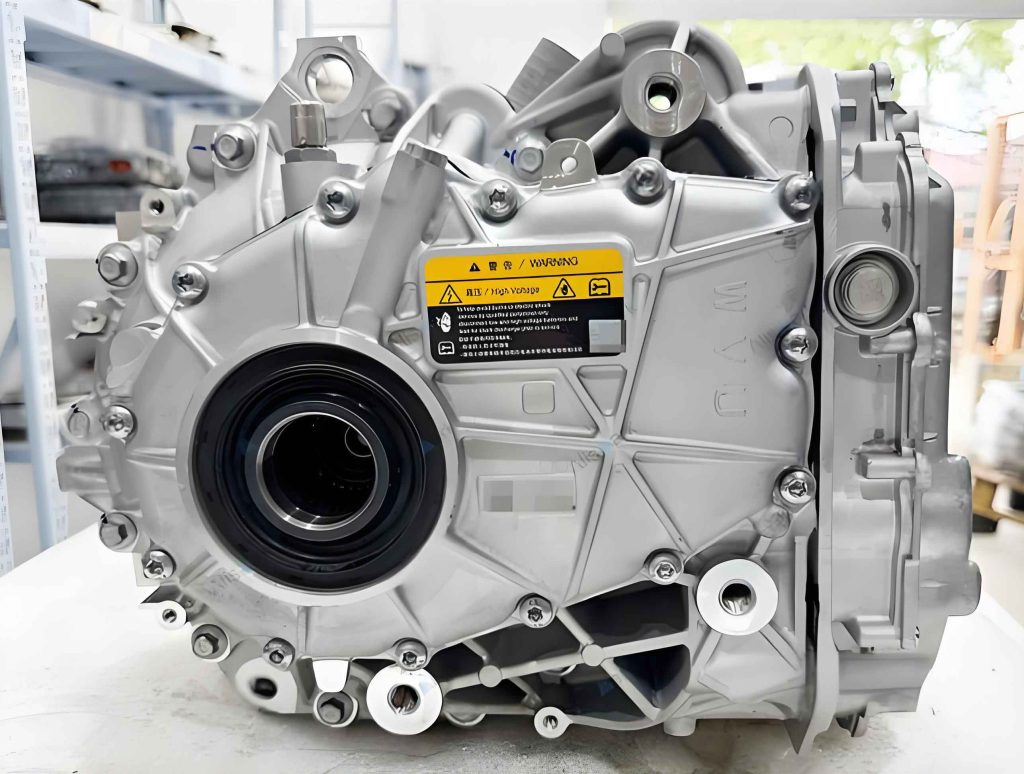
In recent years, with the increasing demand for environmentally friendly transportation and the depletion of fossil fuels, electric vehicles have emerged as a dominant focus in the automotive industry. The electric drive unit, which integrates a motor and a reducer, plays a crucial role in the performance and comfort of electric vehicles. However, due to its high operational speeds, rapid torque response, and the absence of traditional engine masking effects, noise, vibration, and harshness (NVH) issues associated with the electric drive unit have become critical challenges that need urgent resolution. In this study, I investigate the noise problems of an electric drive unit in an electric vehicle, focusing on identifying the sources through experimental analysis and proposing optimization strategies for both structural resonance and electromagnetic excitation. The goal is to provide a comprehensive approach to controlling noise in electric drive units, thereby enhancing passenger comfort and vehicle quality.
The electric drive unit consists of a permanent magnet synchronous motor (PMSM) coupled with a two-stage reducer. The PMSM has 10 poles and 12 slots, and the reducer parameters include gear ratios that influence the vibrational characteristics. The noise generated by the electric drive unit can be attributed to two primary pathways: airborne transmission, where vibrations from the unit radiate noise directly into the cabin, and structural transmission, where vibrations propagate through components like half-shafts and suspensions, causing secondary noise radiation. Through extensive testing and analysis, I have identified that the main noise sources are structural resonance and electromagnetic forces, which exacerbate the overall NVH performance.
To understand the noise mechanisms, I conducted vehicle-level acoustic and vibration tests under various operating conditions, including acceleration, deceleration, and steady-state scenarios. The testing setup involved placing sound pressure sensors near the driver’s ear and above the electric drive unit, and tri-axial vibration accelerometers at key locations such as the motor input/output, reducer input/output, and leaf springs. Data acquisition was performed using an LMS SCADAS III front-end with LMS Test.Lab software, ensuring accurate signal recording. The results from these tests revealed distinct noise orders corresponding to electromagnetic excitations and gear meshing frequencies, highlighting the dominance of electromagnetic noise in the electric drive unit.
In acceleration tests, the vibration amplitudes increased with motor speed, with the motor casing showing the most significant changes. The noise orders identified included the 10th order from electromagnetic forces, the 12th order from stator slot harmonics, and gear meshing orders at 5.2 and 13. These orders contributed substantially to the overall sound pressure level, especially at higher speeds where electromagnetic noise became prominent. In deceleration tests, resonance bands were observed around 890-910 Hz and 1147-1205 Hz, indicating potential structural resonances in the electric drive unit. Steady-state tests at speeds of 10, 20, 30, and 40 km/h showed vibration peaks at frequencies related to the motor’s electrical frequency, with a notable peak at 883.4 Hz corresponding to twice the supply frequency. This suggests that electromagnetic force waves are exciting the structure, leading to amplified vibrations and noise.
The electromagnetic noise in the electric drive unit primarily stems from the PMSM, where radial and tangential force densities are generated due to the interaction between rotor magnets and stator windings. According to Maxwell’s stress tensor method, the radial force density $F_{rad}$ and tangential force density $F_{tan}$ can be expressed as:
$$F_{rad} = \frac{1}{2\mu_0} (b_n^2 – b_t^2)$$
$$F_{tan} = \frac{1}{\mu_0} b_n b_t$$
where $b_n$ and $b_t$ are the radial and tangential magnetic flux densities, respectively, and $\mu_0$ is the permeability of free space ($\mu_0 = 4\pi \times 10^{-7}$ H/m). The force wave orders and frequencies are derived from stator and rotor harmonics, given by:
$$r = (\nu \pm \mu)p$$
$$f_r = (u \pm 1)f$$
Here, $r$ is the force wave order, $f_r$ is the excitation frequency, $\nu$ and $\mu$ are harmonic numbers, $p$ is the pole pair number, and $f$ is the supply frequency. For the PMSM in this electric drive unit, with $p=5$, the dominant force waves occur at orders 0 and 10, with frequencies that align with the observed vibration peaks. This confirms that electromagnetic excitation is a key contributor to the noise problem.
To address the structural resonance issue, I developed a finite element model (FEM) of the electric drive unit, considering the coupling between the motor and reducer, material complexities, and coil winding masses. The model was simplified by removing non-essential features and using bonded contacts for components like the iron core and casing. The coil windings were represented as mass additions to the teeth, and bolt connections were approximated. The anisotropic properties of the stator laminations were accounted for to improve accuracy. Modal analysis was performed to extract natural frequencies and mode shapes, and the model was validated through experimental modal testing using impact hammer techniques. The comparison between simulation and test results showed errors within 5%, verifying the reliability of the FEM.
The constrained modal analysis revealed natural frequencies that correlated with the resonance bands observed in tests. For instance, the third constrained mode at 923 Hz was close to the 890-910 Hz resonance band, and the fourth mode at 1198 Hz matched the 1147-1205 Hz band. This indicates that the electric drive unit structure is susceptible to resonance under electromagnetic excitations. To mitigate this, I focused on optimizing the local stiffness based on modal strain energy, which indicates regions of high deformation and low stiffness. The modal strain energy $P_r$ for the $r$-th mode is given by:
$$P_r = \Phi_r^T K \Phi_r$$
where $\Phi_r$ is the mode shape vector and $K$ is the stiffness matrix. High strain energy areas, such as the connection between the motor end cover and reducer, were identified and reinforced by increasing thickness and adding fillets. This optimization reduced the maximum modal strain energy from 2709 J to 1992 J and increased the natural frequencies, as shown in the table below.
| Mode | Natural Frequency Before Optimization (Hz) | Natural Frequency After Optimization (Hz) |
|---|---|---|
| 1 | 352 | 363 |
| 2 | 653 | 703 |
| 3 | 923 | 1002 |
| 4 | 1198 | 1253 |
These changes shifted the resonance frequencies away from the excitation bands, reducing the risk of resonance in the electric drive unit. For example, the second mode frequency increased by 50 Hz, providing a margin from the 883.4 Hz electromagnetic force frequency.
For the electromagnetic noise control, I targeted the cogging torque in the PMSM, as it is a major source of torque ripple and vibration. Cogging torque arises from the interaction between permanent magnets and stator slots, causing periodic variations that excite structural modes. To reduce it, I employed an electromagnetic simulation model of the PMSM, based on the motor parameters listed in the table below.
| Parameter | Value |
|---|---|
| Phase Voltage | 300 V |
| Output Power | 1.2 kW |
| Motor Speed | 5300 rpm |
| Number of Poles | 10 |
| Number of Slots | 12 |
| Stator Outer Diameter | 140 mm |
| Stator Inner Diameter | 88 mm |
| Rotor Outer Diameter | 87 mm |
| Rotor Inner Diameter | 26 mm |
| Permanent Magnet Thickness | 16 mm |
| Permanent Magnet Width | 4 mm |
| Permanent Magnet Height | 45 mm |
| Winding Connection | Star |
The model was used to simulate the motor’s performance under transient conditions, and cogging torque was calculated by de-energizing the windings. To minimize cogging torque, I explored rotor slot modifications, specifically adding auxiliary slots on the rotor teeth. Four factors were considered: slot shape, slot width, slot depth, and slot angle. Each factor had four levels, leading to 256 possible combinations. To efficiently find the optimal design, I used an orthogonal experimental design (L16 array), which reduces the number of tests while maintaining representativeness. The factors and levels are summarized below.
| Factor | Level 1 | Level 2 | Level 3 | Level 4 |
|---|---|---|---|---|
| Slot Shape (A) | Rectangular | Triangular | Circular | Trapezoidal |
| Slot Angle (B) | 6.0° | 6.5° | 7.0° | 7.5° |
| Slot Width (C) | 1 mm | 2 mm | 3 mm | 4 mm |
| Slot Depth (D) | 1.0 mm | 1.5 mm | 2.0 mm | 2.5 mm |
Sixteen representative models were simulated, and the results for cogging torque peak, average output torque, and air-gap magnetic flux density were recorded. The analysis involved calculating the sum and average of results for each factor level, and the range values were used to determine the influence of factors. The table below shows the orthogonal array and results.
| Test No. | A | B | C | D | Cogging Torque Peak (mNm) | Average Output Torque (Nm) | Average Air-gap Flux Density (T) |
|---|---|---|---|---|---|---|---|
| 1 | 1 | 1 | 1 | 1 | 48.47 | 37.41 | 0.783 |
| 2 | 1 | 2 | 2 | 2 | 44.70 | 35.76 | 0.769 |
| 3 | 1 | 3 | 3 | 3 | 39.37 | 33.18 | 0.724 |
| 4 | 1 | 4 | 4 | 4 | 32.13 | 29.52 | 0.656 |
| 5 | 2 | 1 | 2 | 3 | 46.91 | 36.69 | 0.786 |
| 6 | 2 | 2 | 1 | 4 | 48.27 | 37.24 | 0.794 |
| 7 | 2 | 3 | 4 | 1 | 46.12 | 36.31 | 0.777 |
| 8 | 2 | 4 | 3 | 2 | 46.30 | 36.32 | 0.776 |
| 9 | 3 | 1 | 3 | 4 | 39.09 | 33.24 | 0.733 |
| 10 | 3 | 2 | 4 | 3 | 36.46 | 32.00 | 0.708 |
| 11 | 3 | 3 | 1 | 2 | 47.90 | 37.07 | 0.791 |
| 12 | 3 | 4 | 2 | 1 | 46.72 | 36.52 | 0.781 |
| 13 | 4 | 1 | 4 | 2 | 40.67 | 34.03 | 0.741 |
| 14 | 4 | 2 | 3 | 1 | 45.29 | 35.98 | 0.772 |
| 15 | 4 | 3 | 2 | 4 | 45.46 | 35.89 | 0.769 |
| 16 | 4 | 4 | 1 | 3 | 48.01 | 37.06 | 0.790 |
From the range analysis, slot width had the greatest influence on cogging torque, followed by slot shape, slot depth, and slot angle. The optimal combination for minimizing cogging torque while maintaining output torque was identified as A3B4C4D3: circular slot shape, 7.5° slot angle, 4 mm slot width, and 2 mm slot depth. This design was simulated and compared with the original model. The results showed a 23% reduction in cogging torque peak, from 39.32 mNm to 29.88 mNm, with only a minor decrease in average output torque from 37.48 Nm to 34.53 Nm. The efficiency of the optimized electric drive unit was slightly reduced from 91.5% to 90.8%, but this is acceptable given the significant noise reduction.
The combined structural and electromagnetic optimizations led to a substantial improvement in the NVH performance of the electric drive unit. The structural modifications increased resonance frequencies, avoiding excitation from electromagnetic forces, while the rotor slot design reduced cogging torque, thereby minimizing torque ripple and associated vibrations. These changes contribute to a quieter and more comfortable electric vehicle experience. It is important to note that this study focused on steady-state conditions; future work should investigate transient operations and the impact of control strategies, such as harmonic currents from inverters, which may also affect the noise characteristics of the electric drive unit.
In conclusion, through systematic testing and analysis, I have demonstrated that the noise issues in the electric drive unit are primarily due to structural resonance and electromagnetic excitation. By employing finite element modeling and orthogonal experimental design, effective optimization strategies were developed. The structural optimization enhanced local stiffness, shifting natural frequencies away from critical bands, and the electromagnetic optimization reduced cogging torque significantly. These approaches provide valuable insights for noise control in electric drive units, offering a reference for automotive engineers aiming to improve vehicle NVH. The electric drive unit remains a key component in electric vehicles, and ongoing research into its dynamic and electromagnetic properties will continue to drive advancements in this field.