
As an automotive technician, I often delve into the intricate systems that define modern electric vehicles. In this discussion, I will explore the vehicle states and the electric drive system, focusing on their operational principles and components. The electric drive system is the heart of an EV, responsible for converting electrical energy into mechanical motion and vice versa. Understanding these systems is crucial for effective maintenance and repair.
Vehicles today employ sophisticated state management to synchronize functions and reduce network complexity. The Central Gateway Controller (CGW) serves as the master controller for vehicle states, determining them based on various input signals and internal logic. These states dictate which functions are enabled or disabled, optimizing performance and energy efficiency. The electric drive system plays a pivotal role in many of these states, especially during driving operations.
There are four primary vehicle states: Parked Vehicle, Driver Present, Driving, and SW Update. Each state has specific triggers and functionalities, which I will summarize in a table below.
| State | Triggers | Enabled Functions | Key Signals |
|---|---|---|---|
| Parked Vehicle | Driver leaves seat and exits via door, or after software update. | Limited functions in Comfort Enable phase (e.g., infotainment), with time threshold (default 4 hours). | Seat occupancy, door status, power relay. |
| Driver Present | Driver sits in seat and closes door, or presses brake pedal without door closure. | All non-driving user functions activated based on driver profile; systems prepared for driving. | Seat occupancy, door status, brake pedal. |
| Driving | Gear shifted to D or R, brake pedal pressed, and no charging signal. | All user functions activated; driving-related features enabled except charging functions. | Gear position, brake pedal, charging status. |
| SW Update | Remote software update initialized. | Diagnostics, software updates, configuration settings; network communication active. | Update signals, power relay. |
The transition between states can be modeled using state machine logic. For example, the transition from Parked to Driver Present occurs when conditions are met, which can be expressed as: $$ \text{Parked} \xrightarrow{\text{DriverIn} \land \text{DoorClosed}} \text{Driver Present} $$ where $\text{DriverIn}$ represents seat occupancy and $\text{DoorClosed}$ is the door status. The electric drive system remains inactive in Parked state but is primed in Driver Present state.
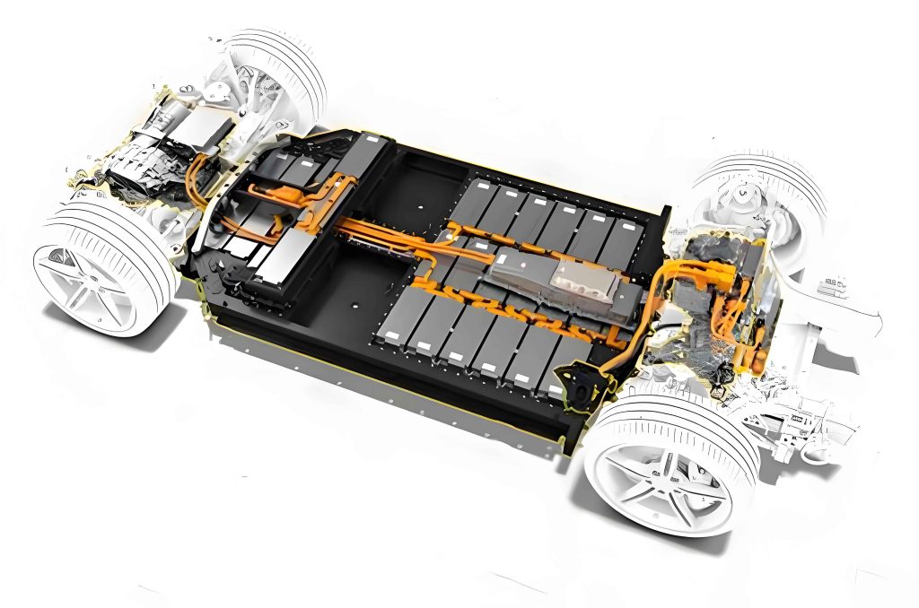
Now, let’s focus on the electric drive system, which is essential for vehicle propulsion. The electric drive system consists of multiple components that work together to deliver torque to the wheels. In many EVs, including the model discussed, the electric drive system is comprised of an inverter, a drive motor, and a gearbox. These elements form a cohesive unit that ensures efficient energy conversion. The electric drive system is designed to handle high power outputs while maintaining reliability.
The inverter is a critical component of the electric drive system. It acts as the control interface, communicating with the Vehicle Control Unit (VCU) to manage torque requests. The inverter converts DC energy from the battery pack into AC energy for the motor during driving, and performs the reverse during regeneration. This process involves power electronics that can be described by formulas such as the power conversion efficiency: $$ \eta_{\text{inv}} = \frac{P_{\text{out}}}{P_{\text{in}}} \times 100\% $$ where $P_{\text{in}}$ is the input DC power and $P_{\text{out}}$ is the output AC power. The electric drive system’s inverter also monitors parameters like voltage, current, and temperature, sending data via CAN network.
There are two inverter variants discussed: 240kW and 160kW. Both serve similar functions but differ in specifications. Below is a table comparing their features within the electric drive system context.
| Parameter | 240kW Inverter | 160kW Inverter |
|---|---|---|
| Power Rating | 240 kW | 160 kW |
| High-Voltage Connections | 2 lines (positive and negative) | 2 lines (positive and negative) |
| AC Connections to Motor | 6 busbars | 3 busbars |
| Communication | CAN with VCU | CAN with VCU |
| Cooling | Liquid-cooled,串联 with motor | Liquid-cooled,串联 with motor |
The drive motor is another key part of the electric drive system. It transforms electrical energy into mechanical torque, with a maximum speed of 15000 rpm. The motor’s performance can be expressed using the torque-speed characteristic: $$ \tau = k_t \cdot I $$ where $\tau$ is torque, $k_t$ is the torque constant, and $I$ is current. The electric drive system motor includes NTC sensors for temperature monitoring and a speed sensor for position feedback, ensuring precise control. The electric drive system relies on these sensors for optimal operation and protection against overheating.
Similar to inverters, drive motors come in 240kW and 160kW versions. Both integrate with the gearbox and inverter to form a complete electric drive system. The table below highlights their differences.
| Parameter | 240kW Motor | 160kW Motor |
|---|---|---|
| Power Rating | 240 kW | 160 kW |
| Max Speed | 15000 rpm | 15000 rpm |
| Sensors | 3 NTC sensors, 1 speed sensor | 3 NTC sensors, 1 speed sensor |
| Connection | Bolted to gearbox and inverter | Bolted to gearbox and inverter |
The gearbox in the electric drive system reduces motor speed and increases torque for wheel propulsion. It uses a single-speed gear ratio, such as 9.599 for the 240kW version and 9.57 for the 160kW version. The torque transmission can be modeled as: $$ \tau_{\text{out}} = \tau_{\text{in}} \cdot r $$ where $r$ is the gear ratio. The electric drive system gearbox lacks a physical neutral, emphasizing simplicity and efficiency. Lubrication is vital, with oil capacities varying by model.
To summarize the gearbox details, here’s a table:
| Parameter | 240kW Gearbox | 160kW Gearbox |
|---|---|---|
| Gear Ratio | 9.599 | 9.57 |
| Oil Capacity (Front) | 1.9 L | 1.3 L |
| Oil Capacity (Rear) | 1.6 L | 1.1 L |
| Function | Torque multiplication, speed reduction | Torque multiplication, speed reduction |
The electric drive system operates in various modes to enhance driving experience. Driving modes include Personalized, Eco, Comfort, and Sport, each with customizable settings. These modes affect parameters like acceleration, regenerative braking, suspension, and steering, all coordinated through the electric drive system components. The table below outlines these modes, highlighting how the electric drive system adapts to different preferences.
| Category | Personalized Mode | Eco Mode | Comfort Mode | Sport Mode |
|---|---|---|---|---|
| Acceleration | Standard or Sport (selectable) | Standard | Standard | Sport |
| Regenerative Braking | Low or Standard (selectable) | Standard | Standard | Low |
| Suspension Height | Standard or Low (selectable) | Auto | Auto | Auto |
| Steering Mode | Stable, Standard, or Light (selectable) | Standard | Light | Stable |
| Electric Drive System Response | Customized torque delivery | Optimized for efficiency | Balanced for comfort | Aggressive for performance |
Regenerative braking is a key feature of the electric drive system, capturing kinetic energy during deceleration. The energy recovered can be expressed as: $$ E_{\text{regen}} = \int P_{\text{regen}} \, dt $$ where $P_{\text{regen}}$ is the regenerative power, dependent on braking force and motor efficiency. The electric drive system inverter facilitates this conversion, feeding energy back to the battery.
Tow mode is another operational aspect, where the electric drive system is disengaged logically. When activated, the parking brake releases, and the VCU sets a logical neutral, allowing towing without damaging the electric drive system. This mode highlights the integration of vehicle states with the electric drive system’s safety features.
In terms of thermal management, the electric drive system relies on liquid cooling. The coolant flows through the inverter and motor in series, dissipating heat generated during operation. The heat dissipation rate can be approximated by: $$ Q = m \cdot c \cdot \Delta T $$ where $m$ is coolant mass flow rate, $c$ is specific heat, and $\Delta T$ is temperature difference. Proper cooling ensures the electric drive system maintains optimal performance and longevity.
The electric drive system’s control logic involves complex algorithms. For instance, torque request from the VCU is processed by the inverter using field-oriented control (FOC), which can be described by equations such as: $$ i_d = 0 \quad \text{(for maximum torque per ampere)} $$ and $$ i_q = \frac{\tau}{k_t} $$ where $i_d$ and $i_q$ are direct and quadrature currents. This precision allows the electric drive system to deliver smooth and responsive power.
Furthermore, the electric drive system contributes to vehicle dynamics. During cornering, torque vectoring can be employed, where the electric drive system adjusts torque to individual wheels, enhancing stability. This involves differential equations like: $$ \Delta \tau = k \cdot \omega_{\text{diff}} $$ where $\omega_{\text{diff}}$ is the wheel speed difference. The electric drive system enables such advanced features through rapid motor control.
In software update state, the electric drive system may undergo firmware upgrades to improve efficiency or add functionalities. This emphasizes the electric drive system’s role in over-the-air updates, ensuring it stays current with technological advancements.
To delve deeper into the electric drive system’s energy flow, consider the overall efficiency chain from battery to wheels: $$ \eta_{\text{total}} = \eta_{\text{inv}} \cdot \eta_{\text{motor}} \cdot \eta_{\text{gearbox}} $$ where each $\eta$ represents the efficiency of respective components. Typical values for the electric drive system range from 85% to 95%, showcasing its superiority over internal combustion systems.
The electric drive system also interfaces with other vehicle networks. For example, CAN messages from the inverter include data packets with information like: $$ \text{CAN ID}: 0x100, \quad \text{Data}: [\text{Voltage}, \text{Current}, \text{Temperature}] $$ This communication ensures the VCU can coordinate the electric drive system with braking, steering, and suspension systems.
In conclusion, the electric drive system is a marvel of modern engineering, integral to vehicle states and driving experiences. From inverters to gearboxes, each component plays a vital role in delivering efficient and powerful propulsion. As technicians, understanding these systems allows us to diagnose issues, perform maintenance, and appreciate the innovation behind electric mobility. The electric drive system continues to evolve, promising even greater performance and sustainability in future vehicles.