
In recent years, the rapid adoption of new energy vehicles (NEVs), particularly electric vehicles (EVs), has revolutionized the automotive industry due to their environmental benefits and energy efficiency. As a professional deeply involved in this field, I have observed that the electronic control system (ECS) is the core technology governing the performance, safety, and reliability of these vehicles. However, the complexity and high integration of the ECS pose significant challenges in fault diagnosis and repair. In this article, I will delve into the intricacies of NEV electronic control systems, analyze common faults, and propose effective maintenance strategies, with a focus on the critical role of the motor control unit. I aim to provide a comprehensive guide that leverages tables and formulas to summarize key concepts, enhancing understanding for technicians and engineers alike.
The electronic control system of a new energy vehicle is essentially the “brain” that coordinates all operational aspects. It comprises several core components, each with distinct functions that interact seamlessly to ensure optimal vehicle performance. Below, I outline these components and their roles, emphasizing how they integrate to form a cohesive system.
| Component | Primary Function | Key Parameters Monitored/Controlled |
|---|---|---|
| Battery Management System (BMS) | Monitors battery state (e.g., voltage, current, temperature), prevents overcharge/discharge, optimizes charging strategies, and extends battery life. | State of Charge (SOC), State of Health (SOH), temperature gradients. |
| Motor Control Unit (MCU) | Regulates motor speed and torque for precise power output; implements control algorithms for acceleration, deceleration, and efficiency. | Torque output, rotational speed, power efficiency. |
| Vehicle Control System (VCS) | Coordinates subsystems (BMS, MCU, braking, steering) via communication networks; processes driver inputs for holistic vehicle management. | System integration status, driver command execution, safety protocol activation. |
From my perspective, the motor control unit is particularly pivotal, as it directly influences driving dynamics and energy consumption. The MCU operates based on control algorithms that can be expressed mathematically. For instance, the torque control in an electric motor often follows a proportional-integral-derivative (PID) model to maintain stability. The error signal e(t) between desired and actual torque is minimized using the formula: $$ u(t) = K_p e(t) + K_i \int_0^t e(\tau) d\tau + K_d \frac{de(t)}{dt} $$ where \( u(t) \) is the control output, and \( K_p \), \( K_i \), and \( K_d \) are tuning constants. This ensures smooth acceleration and responsiveness, highlighting the sophistication embedded in the motor control unit. Beyond these core parts, the ECS incorporates advanced technologies like regenerative braking, which recovers kinetic energy during deceleration. The energy recovered \( E_{rec} \) can be approximated as: $$ E_{rec} = \eta \int_{t_1}^{t_2} P_{brake}(t) dt $$ where \( \eta \) is the efficiency factor and \( P_{brake}(t) \) is the braking power. Additionally, driver-assistance systems such as Anti-lock Braking System (ABS) and Electronic Stability Program (ESP) are integrated, relying on real-time data from sensors and the motor control unit to enhance safety.
Despite these advancements, the ECS is prone to various faults that can compromise vehicle operation. Based on my experience, common issues arise from sensors, actuators, communication networks, and software. These faults often manifest in subtle ways, making diagnosis challenging without systematic approaches.
| Fault Category | Typical Symptoms | Potential Causes | Impact on Motor Control Unit |
|---|---|---|---|
| Sensor and Actuator Faults | Erratic data readings (e.g., speed inaccuracies), loss of signals, slow or failed actuator responses (e.g., motor jerking, brake inefficiency). | Environmental wear, frequent usage, electromagnetic interference, physical damage. | Degraded torque control, unstable power output, increased risk of motor overload. |
| Communication and Software Faults | System crashes, function failures (e.g., inability to start), abnormal dashboard displays, data transmission errors. | Network line aging, poor connectivity, software bugs, update errors, cyber threats. | Disrupted command signals to MCU, leading to unresponsive motor behavior or sudden shutdowns. |
In the context of sensor faults, a mathematical model can describe the deviation. For example, if a temperature sensor in the BMS drifts, the measured value \( T_m \) relates to the actual temperature \( T_a \) as: $$ T_m = T_a + \delta(t) $$ where \( \delta(t) \) is a time-varying error term. This directly affects the motor control unit’s decisions, as thermal management is crucial for motor performance. Similarly, software faults in the MCU’s firmware can cause control loop instability, which might be analyzed using Lyapunov stability criteria: $$ \dot{V}(x) \leq -\alpha V(x) $$ where \( V(x) \) is a Lyapunov function and \( \alpha > 0 \). When this inequality fails due to bugs, the motor control unit may oscillate or fail. To address these issues, I advocate for robust maintenance strategies that combine optimized processes with preventive measures.
Effective maintenance of NEV electronic control systems requires a multifaceted approach. From my viewpoint, streamlining repair workflows and utilizing advanced tools are essential for efficiency, while preventive maintenance and data-driven insights can mitigate faults proactively. Below, I summarize key strategies in a table and elaborate with formulas.
| Strategy | Key Actions | Tools and Techniques | Role of Motor Control Unit |
|---|---|---|---|
| Optimized Repair Processes | Establish step-by-step diagnostic protocols, standardize component replacement procedures, conduct system testing post-repair. | Electronic multimeters, oscilloscopes, diagnostic scanners, programming tools for firmware updates. | MCU-specific diagnostics via software interfaces to calibrate torque parameters and verify control algorithms. |
| Preventive Maintenance and Data-Driven Decisions | Schedule regular inspections (e.g., battery checks, software updates), analyze operational data for trends, implement predictive maintenance models. | Data loggers, cloud analytics platforms, machine learning algorithms for anomaly detection. | Continuous monitoring of MCU performance metrics to preempt failures, such as overheating or efficiency drops. |
In optimizing repair processes, the motor control unit often requires specialized attention. For instance, calibrating the MCU after a sensor replacement involves adjusting PID gains using formulas like: $$ K_p = \frac{2\zeta\omega_n}{K} $$ where \( \zeta \) is the damping ratio, \( \omega_n \) is the natural frequency, and \( K \) is the system gain. This ensures the motor control unit operates within specified tolerances. Regarding preventive maintenance, data-driven decision-making leverages statistical models. Suppose we collect time-series data on MCU temperature \( T(t) \). A predictive model might use regression: $$ \hat{T}(t+1) = \beta_0 + \beta_1 T(t) + \epsilon $$ where \( \hat{T}(t+1) \) is the predicted temperature, \( \beta_0 \) and \( \beta_1 \) are coefficients, and \( \epsilon \) is error. Deviations from predictions can signal impending faults, allowing timely intervention. Moreover, the integration of these strategies enhances overall system reliability. For example, by correlating BMS data with motor control unit performance, we can derive a health index \( H \) for the ECS: $$ H = \sum_{i=1}^n w_i f_i(x_i) $$ where \( w_i \) are weights and \( f_i(x_i) \) are functions of parameters like voltage stability and torque consistency. This holistic view supports proactive repairs.
To visualize the centrality of the motor control unit in these systems, consider the following illustration that depicts its integration within the ECS architecture. It highlights how the motor control unit interacts with other components, underscoring its role in power management and fault diagnostics.
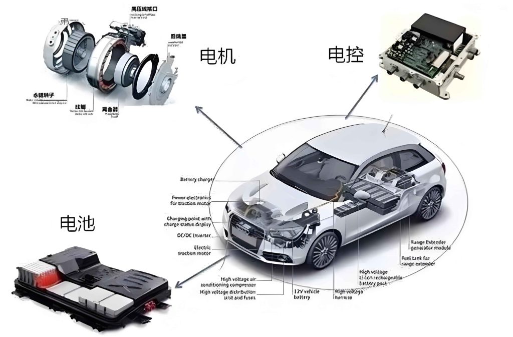
As shown, the motor control unit acts as a hub, processing inputs from the BMS and VCS to drive the electric motor efficiently. This interconnectedness means that any fault in the motor control unit can cascade, affecting vehicle safety and performance. Therefore, in my practice, I emphasize regular software updates for the motor control unit to patch vulnerabilities and enhance control algorithms. The update process can be modeled as a Markov decision process to optimize timing: $$ V(s) = \max_{a} \left( R(s,a) + \gamma \sum_{s’} P(s’|s,a) V(s’) \right) $$ where \( V(s) \) is the value function for system state \( s \), \( a \) is the action (e.g., update now or delay), \( R \) is the reward (e.g., reduced downtime), \( \gamma \) is a discount factor, and \( P \) is the transition probability. This mathematical approach ensures maintenance actions are data-informed.
Looking ahead, the evolution of NEV electronic control systems will demand even more sophisticated maintenance paradigms. From my perspective, ongoing research into fault diagnosis technologies is crucial for improving repair accuracy and system resilience. Innovations in artificial intelligence, such as neural networks for anomaly detection in the motor control unit, hold promise. For instance, a deep learning model could analyze sensor data to predict MCU failures with high precision, using a loss function like: $$ L = -\frac{1}{N} \sum_{i=1}^N y_i \log(\hat{y}_i) $$ where \( y_i \) is the true label and \( \hat{y}_i \) is the predicted probability. By training on historical fault data, such models can reduce diagnostic time and enhance the motor control unit’s longevity. In conclusion, as NEVs become more prevalent, the electronic control system—and particularly the motor control unit—will remain a focal point for maintenance efforts. Through optimized processes, preventive strategies, and data-driven insights, we can ensure these vehicles operate safely and efficiently, paving the way for a sustainable automotive future. I encourage technicians to embrace continuous learning and leverage mathematical tools, as outlined here, to navigate the complexities of NEV repair successfully.