
With the increasing global awareness of environmental protection and the deep-rooted concept of sustainable development, new energy vehicles (NEVs) have become widely adopted. As one of the core technologies in NEVs, the electric control system (ECS) plays a pivotal role in ensuring vehicle performance and driving safety. Its stability and reliability are directly linked to the overall functionality and security of the vehicle. Any malfunction in the ECS can severely impair operational efficiency and even lead to critical safety incidents. Therefore, conducting in-depth research on fault diagnosis and maintenance methods for the ECS is of paramount importance to guarantee the safe, reliable, and efficient operation of NEVs. In this paper, we explore the structure, fault diagnosis techniques, and maintenance strategies for the ECS in NEVs, aiming to provide theoretical foundations and technical support for the healthy development of the industry. Our focus is on enhancing the robustness of the motor control unit, which is central to the ECS, through advanced diagnostic and repair approaches.
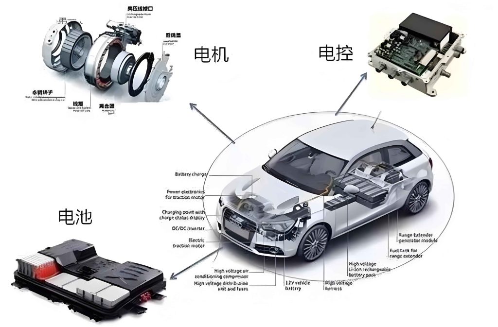
The ECS in NEVs is a complex integration of multiple subsystems that work in harmony to manage energy flow, propulsion, and auxiliary functions. Understanding its architecture is essential for effective fault diagnosis and maintenance. Below, we break down the key components and their interrelationships, with particular emphasis on the motor control unit as a critical element in the electric drive system.
| Component | Primary Function | Key Subsystems |
|---|---|---|
| High-Voltage Battery Pack | Energy storage and power supply | Battery cells, Battery Management System (BMS) |
| Electric Drive System | Conversion of electrical energy to mechanical energy | Motor, Motor Control Unit (MCU), Reduction gear |
| Auxiliary Electrical System | Provision of ancillary services | On-board charger, DC/DC converter, Climate control |
| Body Control System | Monitoring and adjustment of vehicle states | Suspension control, Lighting, Door modules |
The high-voltage battery pack serves as the primary energy source, composed of numerous cells with high energy density and long cycle life. The BMS monitors parameters such as voltage, current, and temperature to prevent overcharging or over-discharging. The electric drive system, which includes the motor and the motor control unit, is responsible for propulsion. The motor control unit regulates the motor’s power output based on driver inputs and system demands, ensuring efficient torque generation. The auxiliary system handles functions like charging and low-voltage power distribution, while the body control system manages comfort and safety features. Throughout this paper, we will repeatedly address the motor control unit due to its significance in fault scenarios.
Fault diagnosis in the ECS relies on a combination of technologies that enable quick identification and analysis of issues. We categorize these into fault code diagnosis, data analysis, and fault pattern recognition, each with its own methodologies and applications. The motor control unit often generates specific fault codes that are crucial for initial diagnosis. Below, we summarize these techniques in a table and delve into mathematical formulations for data analysis.
| Diagnostic Technique | Description | Tools/ Methods |
|---|---|---|
| Fault Code Diagnosis | Reading error codes from the ECS via diagnostic tools to pinpoint failures. | OBD-II scanners, proprietary software |
| Data Analysis | Processing real-time sensor data to assess system health and predict faults. | Signal processing, statistical models |
| Fault Pattern Recognition | Using machine learning to identify fault patterns from historical data. | Wavelet transforms, neural networks |
In fault code diagnosis, the motor control unit typically logs codes such as P0A00 for motor-related issues, which can be retrieved using standardized protocols. For data analysis, we employ mathematical models to evaluate battery and motor performance. For instance, the state of charge (SOC) of the battery can be estimated using ampere-hour integration combined with a Kalman filter, represented as:
$$ SOC(t) = SOC(0) – \frac{1}{C_n} \int_0^t \eta I(\tau) d\tau $$
where \( C_n \) is the nominal capacity, \( \eta \) is the coulombic efficiency, and \( I \) is the current. Similarly, the motor control unit’s output can be analyzed through torque equations, such as:
$$ T = k_t \cdot I $$
where \( T \) is torque, \( k_t \) is the torque constant, and \( I \) is current. Deviations from expected values indicate faults. Fault pattern recognition often involves wavelet transforms for signal decomposition, given by:
$$ W(a,b) = \int_{-\infty}^{\infty} x(t) \psi_{a,b}(t) dt $$
with \( \psi_{a,b}(t) = \frac{1}{\sqrt{a}} \psi\left(\frac{t-b}{a}\right) \), where \( a \) and \( b \) are scale and translation parameters. This helps in detecting anomalies in motor control unit signals, such as irregularities in PWM waveforms.
Maintenance strategies for the ECS must be systematic and safety-oriented to ensure long-term reliability. We propose three core strategies: matching diagnosis results with repair plans, optimizing operational procedures with training, and conducting post-repair performance tests. The motor control unit requires careful handling due to its sensitivity and integration within the system. Below, we outline a detailed maintenance workflow in a table, followed by discussions on each strategy.
| Maintenance Phase | Actions | Focus on Motor Control Unit |
|---|---|---|
| Diagnosis Matching | Align fault codes/data with specific repair steps, ensuring precise interventions. | Verify MCU error logs, check connections, update firmware if needed. |
| Procedure Optimization | Standardize workflows and enhance technician skills through training programs. | Include MCU-specific safety protocols and calibration techniques. |
| Post-Repair Testing | Perform comprehensive tests to validate repairs and ensure system integrity. | Test MCU output signals, monitor temperature, and verify communication. |
In the diagnosis matching phase, we emphasize correlating fault indicators from the motor control unit with actionable repair steps. For example, if a fault code indicates an overcurrent condition in the motor control unit, the repair plan might involve inspecting power transistors, checking wiring insulation, and recalibrating control parameters. This requires deep knowledge of the motor control unit’s architecture, which includes microcontrollers, gate drivers, and sensors. We often use diagnostic software to read live data from the motor control unit, such as phase currents and voltages, to confirm issues before disassembly.
Optimizing maintenance procedures involves creating detailed checklists and safety guidelines. Since the motor control unit operates at high voltages, technicians must wear insulated gear and ensure power disconnection. Training programs should cover topics like motor control unit programming, signal interpretation, and emergency handling. We recommend regular workshops to keep pace with advancements in motor control unit technology, as newer models may feature more complex algorithms. For instance, a typical procedure for servicing the motor control unit includes:
- Isolate the high-voltage system and discharge capacitors.
- Use multimeters and oscilloscopes to measure signals at the motor control unit terminals.
- Compare readings with manufacturer specifications, using formulas like \( V_{phase} = \sqrt{3} \cdot V_{line} \) for three-phase systems.
- If replacement is needed, ensure compatibility and perform software matching.
Post-repair performance testing is critical to avoid recurrent faults. For the motor control unit, we conduct dynamic tests under various load conditions to verify its response. This includes checking the torque output using the equation \( T = \frac{P}{\omega} \), where \( P \) is power and \( \omega \) is angular velocity. Additionally, we monitor communication networks like CAN bus for errors originating from the motor control unit. A comprehensive test suite might involve:
- Battery load tests to ensure stable voltage supply to the motor control unit.
- Motor efficiency calculations based on \( \eta = \frac{P_{out}}{P_{in}} \times 100\% \).
- Thermal imaging of the motor control unit to detect overheating spots.
These steps help in validating that the motor control unit functions within safe limits and integrates seamlessly with other ECS components.
In conclusion, the electric control system is fundamental to the efficient operation of new energy vehicles, and its fault diagnosis and maintenance require a multifaceted approach. By leveraging technologies like fault code analysis, data-driven models, and pattern recognition, we can swiftly identify issues, particularly those involving the motor control unit. Maintenance strategies must be tailored to match diagnostic outcomes, reinforced by standardized procedures and rigorous testing. Through continuous research and innovation, we aim to enhance the reliability of the motor control unit and the overall ECS, thereby supporting the sustainable growth of the new energy vehicle industry. Future work will focus on integrating artificial intelligence for predictive maintenance and developing more resilient motor control unit designs.