
In my years of experience as an automotive technician, I have witnessed the rapid evolution of vehicle propulsion systems. The advent of electronically controlled engine systems, which integrate mechanical, electronic, and computational technologies, has revolutionized automotive performance, fuel efficiency, and emissions. At the heart of this system lies the motor control unit, a sophisticated computer that processes sensor data and commands actuators to optimize engine operation. However, the complexity of these systems, particularly the intricate network centered on the motor control unit, makes them susceptible to various faults. This article explores fault diagnosis and maintenance techniques from my first-hand perspective, aiming to enhance repair efficiency and ensure vehicle safety and reliability.
The modern automotive engine is no longer a purely mechanical device; it is a cyber-physical system where the motor control unit plays the pivotal role. This unit continuously receives data from an array of sensors monitoring parameters like crankshaft position, air mass flow, oxygen content in exhaust, coolant temperature, and throttle position. Based on pre-programmed maps and algorithms, the motor control unit calculates optimal outputs for fuel injection, ignition timing, and idle speed control. The precision offered by the motor control unit allows for exceptional adaptability to different driving conditions. Yet, this reliance on electronics means that any malfunction within the sensor-motor control unit-actuator loop can lead to significant performance issues, ranging from poor drivability to complete engine failure. Therefore, mastering diagnostic and repair methodologies is paramount.
Fault Diagnosis Strategies for Electronically Controlled Engines
Diagnosing faults in these systems requires a blend of advanced tooling and nuanced human expertise. I generally categorize the approaches into instrumental diagnosis and experiential, or manual, diagnosis.
Instrumental Diagnosis
The use of specialized diagnostic instruments is often the first line of defense. These tools communicate directly with the vehicle’s onboard diagnostics (OBD) system, primarily interfacing with the motor control unit. A scan tool can read Diagnostic Trouble Codes (DTCs) stored in the motor control unit’s memory when a fault is detected. However, codes only indicate a problem area, not the root cause. For deeper analysis, I utilize data streaming. This function allows real-time observation of sensor inputs and actuator commands as processed by the motor control unit. For instance, by comparing the actual throttle position sensor voltage to the commanded value from the motor control unit, one can identify discrepancies.
Beyond code readers, electrical measurements are fundamental. A high-quality digital multimeter (DMM) and an oscilloscope are indispensable. When a circuit related to the motor control unit is suspect, I follow a logical testing procedure. Consider a scenario where an engine cranks but fails to start. A simple voltage check at the fuel pump relay control circuit, which is commanded by the motor control unit, can reveal if the command signal is present. The relationship between voltage, current, and resistance in these circuits is governed by Ohm’s Law, which is constantly applied:
$$ V = I \times R $$
where \( V \) is voltage, \( I \) is current, and \( R \) is resistance. If the motor control unit commands a relay to close (low resistance path), but a voltage drop is detected across the switch, it suggests high resistance or an open circuit. Short circuits, often caused by insulation failure, can be identified by a fused link blowing, which follows the power dissipation formula:
$$ P = I^2 \times R $$
A sudden surge in current \( I \) dramatically increases power \( P \), leading to fuse failure. Oscilloscopes are particularly valuable for analyzing dynamic signals, such as those from crankshaft position sensors or injector pulses initiated by the motor control unit. A distorted or absent waveform can pinpoint a faulty sensor or a wiring issue before it reaches the motor control unit.
| Test Instrument | Primary Function | Typical Measurement Related to Motor Control Unit |
|---|---|---|
| OBD-II Scan Tool | Read/Clear DTCs, view live data stream | Retrieves fault codes from motor control unit memory; displays sensor inputs (e.g., MAF, O2) and output states. |
| Digital Multimeter (DMM) | Measure DC/AC voltage, current, resistance, frequency | Checks power supply to motor control unit, sensor reference voltages, signal wire continuity, actuator coil resistance. |
| Oscilloscope | Graphically visualize electrical signals over time | Analyzes waveform integrity of crank/cam sensors, ignition primary/secondary signals, injector pulses commanded by motor control unit. |
| Fuel Pressure Gauge | Measure fuel delivery system pressure | Verifies that the fuel pump (often controlled by motor control unit via relay) is providing adequate pressure for commanded injection. |
| Exhaust Gas Analyzer | Measure concentrations of exhaust gases | Assesses combustion efficiency, validating the fuel trim adjustments made by the motor control unit based on oxygen sensor feedback. |
Experiential (Manual) Diagnosis
While instruments provide quantitative data, they cannot replicate human senses and heuristic reasoning. Manual diagnosis complements instrumental methods. This approach relies heavily on the technician’s sensory perception and systematic logical deduction. For example, a subtle misfire might not immediately set a code in the motor control unit, but it can be felt as a vibration or heard as an irregular exhaust note. Smelling unburned fuel or seeing abnormal smoke color provides immediate clues. I often perform component substitution based on probability and symptom analysis before conclusive instrumental testing, especially for intermittent faults that evade scanner detection. The process involves understanding system interdependencies. A faulty coolant temperature sensor sending a permanently cold signal to the motor control unit will cause the unit to enrich the fuel mixture excessively, leading to poor fuel economy and rough idle—symptoms that can be initially assessed without tools. However, the limitation is reproducibility and potential for misdiagnosis if experience is lacking. The synergy between instrument and experience is key; the instrument validates the hypothesis formed through manual inspection.
Core Maintenance Techniques for System Components
Once a fault is isolated, precise repair is essential. The system can be divided into three core areas: sensors, actuators, and the central controller—the motor control unit.
Sensor Fault Remediation
Sensors are the eyes and ears of the motor control unit. Their failure leads to erroneous data input, causing the motor control unit to make flawed calculations. The repair process involves verification, testing, and replacement.
Oxygen (O2) Sensor: This sensor is critical for closed-loop fuel control. It operates on the Nernst principle, generating a voltage based on the difference in oxygen partial pressure between the exhaust gas and the ambient air. The output voltage \( V_{O2} \) is approximated by the Nernst equation:
$$ V_{O2} = \frac{RT}{4F} \ln\left(\frac{P_{O2,\text{air}}}{P_{O2,\text{exhaust}}}\right) $$
where \( R \) is the gas constant, \( T \) is the absolute temperature, \( F \) is Faraday’s constant, and \( P_{O2} \) are partial pressures. A faulty sensor may show a sluggish response, a stuck rich/lean signal, or no activity. Diagnosis involves checking heater circuit resistance (typically 5-20 Ω) and observing the signal voltage swing between 0.1V (lean) and 0.9V (rich) with a DMM or scope. If out of specification, replacement is necessary after confirming wiring integrity back to the motor control unit.
Mass Air Flow (MAF) Sensor: It measures the mass of air entering the engine. A common type is the hot-wire sensor. The motor control unit passes a current through a platinum wire to maintain it at a constant temperature above ambient. The cooling effect of incoming air requires more electrical power, which is proportional to mass flow. The governing heat transfer principle can be summarized as:
$$ I^2 R_w = h A (T_w – T_a) $$
Here, \( I \) is the current, \( R_w \) is wire resistance, \( h \) is heat transfer coefficient, \( A \) is surface area, \( T_w \) is wire temperature, and \( T_a \) is air temperature. Contamination on the wire alters \( h \), causing inaccurate readings. Cleaning with specialized MAF cleaner is the first step. Failure often leads to data stream values that are static, implausibly high/low, or unresponsive to throttle changes. A comparison between MAF readings and calculated load based on engine speed and manifold pressure can reveal discrepancies.
Crankshaft Position (CKP) Sensor: This sensor provides the essential timing reference for the motor control unit to synchronize ignition and injection. Magnetic reluctance sensors generate an alternating voltage as a toothed reluctor wheel passes. The induced voltage \( \epsilon \) is given by Faraday’s law:
$$ \epsilon = -N \frac{d\Phi_B}{dt} $$
where \( N \) is the number of coil turns and \( \frac{d\Phi_B}{dt} \) is the rate of change of magnetic flux. A fault here often prevents engine start. Testing involves checking coil resistance (usually 200-2000 Ω) and inspecting the AC voltage output while cranking (typically 0.5-2.0 V AC). An oscilloscope shows the sinusoidal waveform; missing or irregular pulses indicate a problem. The air gap between sensor and reluctor is critical and must be within specification (e.g., 0.5-2.0 mm).
| Sensor | Typical Fault | Engine Symptom | Key Diagnostic Measurements | Standard Range Example |
|---|---|---|---|---|
| Oxygen Sensor (Heated) | Heater failure, contamination, slow response | High fuel consumption, elevated emissions, rough idle, stored rich/lean codes in motor control unit. | Heater resistance, signal voltage activity (0.1-0.9V), response time. | Heater Res: 5-20 Ω; Signal Freq: ~1 Hz at idle. |
| Mass Air Flow (MAF) | Contaminated hot wire/element, circuit fault | Hard start, hesitation, stalling, lack of power. | Output voltage/Hz at different RPMs, comparison with MAP-derived load in motor control unit data. | Voltage: 0.5-5.0V corresponding to 0-∞ g/s flow. |
| Coolant Temp (ECT) | Resistance drift, open/short circuit | Poor cold start, overheating fan not activating, incorrect fuel mixture. | Resistance vs. Temperature curve. Use DMM and thermometer. | e.g., 3000 Ω @ -10°C, 300 Ω @ 50°C, 30 Ω @ 100°C. |
| Crankshaft Position (CKP) | Coil damage, incorrect gap, debris on reluctor | No-start, intermittent stalling, misfire. | AC voltage output while cranking, resistance, waveform shape on oscilloscope. | Resistance: 200-2000 Ω; AC Voltage: >0.5V while cranking. |
| Throttle Position (TPS) | Wear in potentiometer, poor contact | Surge during acceleration, erratic idle, hesitation. | Voltage sweep from closed to open throttle (smooth, linear). Check at motor control unit connector. | Closed: ~0.5V, Wide Open: ~4.5V (for 5V reference). |
Actuator Fault Remediation
Actuators execute the commands from the motor control unit. Common actuators include fuel injectors, ignition coils, and throttle actuators.
Fuel Injectors: These are solenoid-operated valves controlled by pulsed signals from the motor control unit. The motor control unit calculates the required injection pulse width \( t_{inj} \) based on engine load and speed. A clogged or leaky injector disrupts fuel delivery. Testing involves checking coil resistance (typically 10-20 Ω for high-impedance types), listening for a clicking sound with a stethoscope during operation, and performing a balance test to compare flow rates. A leak-down test checks for dribbling after the engine is off. Cleaning via ultrasonic bath or replacement is the remedy.
Ignition Coils: They transform the low-voltage signal from the motor control unit into a high-voltage spark. The coil operates on the principle of mutual induction. The energy stored in the primary coil \( E_p \) is given by:
$$ E_p = \frac{1}{2} L_p I_p^2 $$
where \( L_p \) is primary inductance and \( I_p \) is primary current broken by the motor control unit command. This energy is transferred to the secondary circuit to produce a high-voltage spark. Faults cause misfires. Testing includes measuring primary resistance (0.5-3.0 Ω) and secondary resistance (5,000-30,000 Ω). An oscilloscope test of the primary current ramp and secondary voltage waveform is definitive. A weak or open coil must be replaced.
Electronic Throttle Body (Actuator): This device uses a DC motor, precisely controlled by the motor control unit via pulse-width modulation (PWM), to regulate throttle plate angle. Faults lead to idle control problems and reduced power modes. Diagnosis involves checking motor resistance (usually a few ohms), inspecting gear train for binding, and verifying the feedback signals from the throttle position sensors (often dual for redundancy) to the motor control unit. After any repair or replacement, a throttle learn procedure—where the motor control unit recalibrates the closed and open positions—is mandatory.
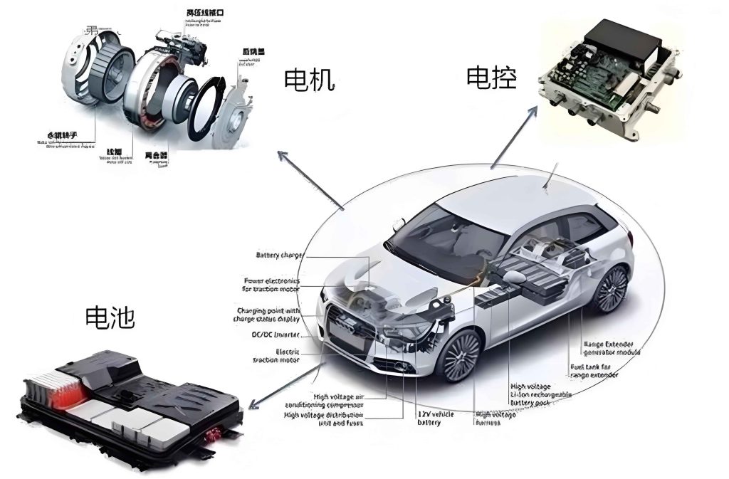
The image above illustrates a typical motor control unit, showcasing its complex circuit board and connectors. This unit is the nexus where all sensor data converges and all actuator commands originate. Understanding its role is fundamental to diagnosing systemic issues.
Motor Control Unit (ECU) Fault Remediation
The motor control unit itself, while robust, can fail. Issues can be software-related (corruption, calibration mismatch) or hardware-related (physical damage). As the core processor, the motor control unit executes control laws that can be represented by transfer functions. For example, the fuel injection calculation might involve a multidimensional map:
$$ t_{inj} = f(N, L, T_{cool}, \lambda_{feedback}, …) $$
where \( N \) is engine speed, \( L \) is load, \( T_{cool} \) is coolant temperature, and \( \lambda_{feedback} \) is the air-fuel ratio feedback from the O2 sensor. If the motor control unit has corrupted memory, this function can yield erroneous outputs.
Software/Calibration Issues: These may arise from battery disconnections, flash programming interruptions, or compatibility problems. Symptoms are often bizarre and inconsistent. Remediation involves using a professional diagnostic programming tool to reflash the motor control unit with the correct software calibration. This process rewrites the program memory and data maps within the motor control unit.
Hardware Failures: Physical damage can result from water ingress, voltage spikes, or thermal stress. Components like power transistors driving injectors or ignition coils, voltage regulators, or the main microprocessor can fail. Diagnosing a faulty motor control unit is a process of elimination. First, ensure all power supplies (constant battery, ignition-switched) and grounds to the motor control unit are perfect, using voltage drop tests:
$$ V_{drop} = V_{source} – V_{load} $$
A drop greater than 0.1V on a ground circuit under load is problematic. If power and grounds are good, and all sensor inputs verified at the motor control unit connector are plausible, but outputs are missing or incorrect, the motor control unit is suspect. Advanced repair involves board-level diagnostics with an oscilloscope and possibly replacing surface-mount components. However, due to complexity and proprietary coding, replacement with a new or remanufactured unit is often the practical solution. After replacement, the new motor control unit frequently requires vehicle-specific programming (VIN programming, immobilizer pairing, and parameter learning) to function correctly. This step is crucial and underscores the motor control unit’s role as the vehicle’s central nervous system.
| Symptom / Test Result | Possible Cause | Diagnostic Action | Repair Action |
|---|---|---|---|
| No communication with scan tool. | Faulty motor control unit power/ground, damaged OBD circuit, or dead motor control unit. | Check fuses, measure voltage at motor control unit pins (B+ and Ignition). Check CAN bus resistance (typically 60Ω between pins). | Repair wiring. If power/ground good and bus resistance OK, replace motor control unit. |
| Multiple, implausible sensor codes across unrelated systems. | Bad motor control unit ground or reference voltage circuit, internal motor control unit fault. | Check sensor common 5V reference from motor control unit for stability and correct value. Check all motor control unit grounds for resistance. | Repair reference voltage circuit or ground. If internal fault, replace motor control unit. |
| Intermittent operation, resets when hot/tapped. | Poor solder joint, cracked circuit board inside motor control unit, thermal failure of component. | Monitor motor control unit power pins for dropouts during fault. Gentle manipulation of motor control unit/harness while monitoring data. | Usually requires motor control unit replacement or specialized board repair. |
| Single, consistent output driver failure (e.g., one injector never fires). | Blown driver transistor within motor control unit for that circuit. | Swap actuator (e.g., injector) with another channel. If fault follows channel, motor control unit driver is faulty. Verify by checking command signal at motor control unit pin with scope. | Replace motor control unit or seek professional board repair to replace the specific driver IC. |
| Configuration/calibration error after battery replacement. | Software corruption or lost adaptive memory in motor control unit. | Use scan tool to check for “configuration not accepted” or similar codes. Review adaptive values. | Perform motor control unit reset/relearn procedures via scan tool. May require flashing. |
Integrative Diagnostic Approach and Future Perspectives
In practice, diagnosing a fault is rarely linear. It involves a cyclical process of observation (using both instruments and senses), hypothesis formation, testing, and validation. A systematic approach is vital. I often start with a visual inspection, followed by scanning for codes from the motor control unit, then analyzing live data to confirm the plausibility of sensor readings. For instance, if the motor control unit reports a low coolant temperature but the engine is warm, I investigate the ECT sensor circuit before condemning the motor control unit itself. Wiring diagrams and knowledge of the motor control unit’s pinout are essential to perform “pin-to-pin” tests, verifying signals directly at the unit’s connector.
The future of diagnosis is leaning towards greater integration with the motor control unit. On-board diagnostics are becoming more advanced, with capabilities for continuous component monitoring and even predictive fault reporting. Wireless telematics can transmit motor control unit data to manufacturers for analysis. As vehicles evolve towards electrification and higher automation, the role of the motor control unit will expand further, potentially integrating with battery management and autonomous driving systems. This will necessitate even more sophisticated diagnostic tools and continuous technician training. The core principles, however—understanding electrical fundamentals, systematic testing, and recognizing the motor control unit as the central decision-maker—will remain timeless.
To conclude, the effective diagnosis and repair of automotive electronically controlled engine systems demand a deep understanding of the interplay between sensors, actuators, and the central motor control unit. Mastery requires proficiency with advanced diagnostic instruments, sharpened by hands-on experience and deductive reasoning. As these systems grow more complex, the technician’s role evolves from a parts changer to a systems analyst and software manager. The relentless focus must be on precision, for an error in diagnosing a signal to or from the motor control unit can have cascading effects. By adhering to methodical procedures, leveraging both quantitative data and qualitative assessment, and respecting the sophistication of the modern motor control unit, we can ensure these marvels of engineering continue to deliver their promised performance, efficiency, and reliability on the road.