
In the context of national energy conservation and emission reduction policies, the demand for high-efficiency industrial drives has intensified. Our team embarked on a project to develop a high-speed, large-capacity asynchronous motor specifically for electric drive systems in critical applications such as blast furnace blower units. This electric drive system is integral to modernizing industrial processes, and our goal was to create a motor that meets rigorous performance, reliability, and efficiency standards. The development focused on electromagnetic design, structural integrity, thermal management, and validation through testing, all tailored for integration into advanced electric drive systems.
The motor is designed for use in Blast furnace air Blower and Power Recovery Turbine (BPRT) units, where it works in tandem with a gas expansion turbine to reduce net shaft power and save energy. As grid capacities have expanded, users have begun adopting asynchronous motors exceeding 30 MW. Our project aimed to push this boundary, resulting in a 38 MW prototype that represents a significant advancement in electric drive system technology. This motor employs a single high-voltage frequency converter for control, enabling soft-start capabilities and optimized performance across the operational range, which is crucial for the dynamic demands of electric drive systems.
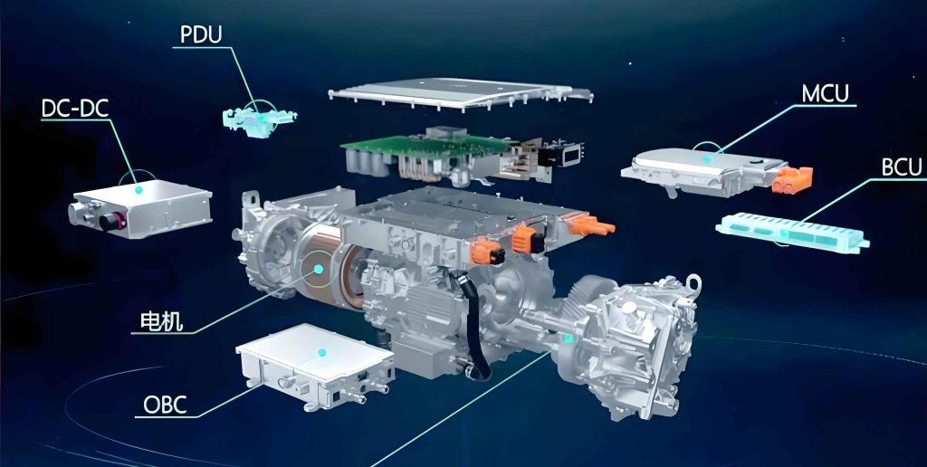
In the electromagnetic design phase, we prioritized factors essential for high-performance electric drive systems. Large-capacity motors often use bar-type windings to minimize circulating current losses. We innovated by researching winding phase-band splitting and parallel connection techniques, achieving breakthroughs that reduce cost and enhance production efficiency. Since the motor is fed by a frequency converter, the windings endure high surge voltages, necessitating enhanced turn-to-turn insulation. The surge voltages, superimposed on operating voltages, can accelerate aging of ground insulation. Therefore, we selected a reliable Class F insulation system to ensure longevity in demanding electric drive system environments.
The electromagnetic parameters were chosen to meet BPRT unit requirements, with maximum thermal factors adhering to temperature rise limits, peak magnetic parameters within material capabilities, and torque multiples satisfied at the highest frequency points. The rated efficiency and power factor were optimized for the electric drive system. We utilized mature in-house calculation programs to determine the electromagnetic scheme. Key electrical parameters are summarized in the table below, which aligns with user specifications for the electric drive system.
| Parameter | Value |
|---|---|
| Rated Power (kW) | 38000 |
| Rated Voltage (V) | 10000 |
| Rated Current (A) | 2458 |
| Rated Speed (r/min) | 1496 |
| Cooling Method | IC81W |
| Rated Efficiency (%) | 98.0 |
| Full-Load Power Factor | 0.911 |
| Locked-Rotor Current Multiple | 4.36 |
| Locked-Rotor Torque Multiple | 0.36 |
| Maximum Torque Multiple | 1.8 |
| Insulation Class | F |
| Protection Class | IP55 |
| Overall Dimensions (L×W×H, mm) | 5670 × 3969 × 4410 |
| Total Weight (t) | 70 |
To validate the design, we performed advanced finite element analysis (FEA) simulations. The electromagnetic field distribution, torque ripple, and current waveforms were analyzed to ensure accuracy. The magnetic field simulation confirmed uniform flux density, critical for stable operation in electric drive systems. The torque ripple was minimized to reduce mechanical stress, and the current waveform adhered to sinusoidal expectations under变频 conditions. The electromagnetic torque can be expressed as: $$T_e = \frac{3}{2} p \left( \psi_d i_q – \psi_q i_d \right)$$ where $T_e$ is the electromagnetic torque, $p$ is the number of pole pairs, $\psi_d$ and $\psi_q$ are d- and q-axis flux linkages, and $i_d$ and $i_q$ are d- and q-axis currents. This formula underpins our torque optimization for the electric drive system.
The structural design of the motor was tailored for robustness in high-speed electric drive systems. The motor features a squirrel-cage asynchronous design with a fully enclosed water-cooled循环 system and end-shield sliding bearings. The structure includes a stator (comprising frame, core, and windings), rotor (with core, bars, end rings, fans, and shaft), and two end shields with bearings. Auxiliary components such as main terminal boxes, neutral point boxes, heater boxes, and temperature measurement boxes are mounted on the side. The main shaft extension is cylindrical with a keyway, while the non-drive end can accommodate speed measurement devices.
Bearing selection was critical due to the high rotor weight and dynamic performance requirements. We opted for elliptical sliding bearings with high oil film stiffness and damping coefficients to support the large inertia and prolonged starting via the frequency converter in the electric drive system. A high-low pressure oil supply system was implemented: high-pressure oil lifts the rotor during start-up to reduce friction, while low-pressure circulation provides lubrication during normal operation. The bearing parameters were calculated to ensure reliability, as summarized below.
| Parameter | Non-Drive End | Drive End |
|---|---|---|
| Working Load (N) | 123448 | 130724 |
| Average Bearing Pressure (MPa) | 1.687 | 1.787 |
| Minimum Oil Film Thickness (mm) | 0.067 | 0.064 |
| Power Loss (kW) | 17.67 | 17.79 |
| Maximum Oil Film Temperature (°C) | 79.4 | 80.0 |
| Stiffness Coefficient Kxx (N/m) | 5.86×10⁸ | 6.27×10⁸ |
| Stiffness Coefficient Kxy (N/m) | -1.17×10⁸ | -7.15×10⁷ |
| Stiffness Coefficient Kyx (N/m) | 1.70×10⁹ | 1.82×10⁹ |
| Stiffness Coefficient Kyy (N/m) | 2.66×10⁹ | 2.91×10⁹ |
| Damping Coefficient Dxx (N·s/m) | 4.18×10⁶ | 4.18×10⁶ |
| Damping Coefficient Dxy (N·s/m) | 3.77×10⁶ | 3.77×10⁶ |
| Damping Coefficient Dyy (N·s/m) | 2.24×10⁷ | 2.37×10⁷ |
| Bearing Nominal Diameter (mm) | 335.0 | |
| Bearing Effective Width (mm) | 218.5 | |
| Relative Clearance (‰) | 0.8 | |
| Rated Speed (r/min) | 1496 | |
| Preload Factor | 0.528 | |
| Lubricant Type | L-TSA46 | |
| Oil Flow (L/min): Low Pressure / High Pressure | 52 / 6 | |
| Inlet Oil Temperature (°C) | 40 | |
The stator design employed an external pressure assembly structure. The core is tightened with tie rods, and after pressing, channel steels and lifting pieces are welded in place. Sixteen channel steels均匀 distributed around the circumference provide radial stiffness, while end plates ensure axial compression. The stator windings, once inserted, are secured with slot wedges in the straight sections. The end portions are fixed using end-binding structures, with insulating materials packed between coils and bound with glass-fiber ropes, followed by vacuum VPI impregnation and curing. This enhances mechanical strength and insulation integrity for the electric drive system.
The stator frame is a box-type structure welded from steel plates, with reinforcing ribs added for increased stiffness and strength to protect the core and windings. Internal frame walls and external止口配合 with end shields ensure alignment. Ventilation openings on the top plate accommodate coolers, while side panels have windows for terminal boxes. The symmetric internal air circuit, driven by shaft-mounted fans, was optimized for cooling efficiency. We increased the frame width to improve ventilation and enlarged the bottom support plates for enhanced strength.
The rotor consists of a forged shaft, core, bars, end rings, and fans. The shaft features a milled-rib design to reduce weight while maintaining rigidity. The rotor deflection was kept below 10% of the air gap, and the first vertical critical speed exceeds 1.3 times the rated speed, ensuring stability in high-speed electric drive systems. The interference fit between the rotor core and shaft满足 torque transmission requirements. We performed rotor dynamics analysis using ANSYS finite element software to compute critical speeds, confirming reliability. The rotor natural frequency $f_n$ can be estimated using: $$f_n = \frac{1}{2\pi} \sqrt{\frac{k}{m}}$$ where $k$ is the stiffness and $m$ is the mass, though more complex FEA models were used for accuracy.
Given the high power density, ventilation and散热 were critical. We optimized the internal air path using computational fluid dynamics (CFD) simulations. The风压 distribution and fan performance were analyzed to improve airflow and heat dissipation. By refining the ventilation structure and increasing heat transfer areas, we enhanced cooling effectiveness. This allowed us to adopt an IC81W cooling method instead of the more common IC86W for motors above 25 MW, reducing auxiliary power consumption and potential failure points in the electric drive system. The heat transfer equation $$Q = h A \Delta T$$ where $Q$ is heat transfer rate, $h$ is convective coefficient, $A$ is area, and $\Delta T$ is temperature difference, guided our design to maximize $A$ and $h$.
The cooler structure was integrated into the frame, utilizing a closed-loop water system. The IC81W method relies on internal air circulation cooled by water-to-air heat exchangers, eliminating the need for external fans and simplifying the electric drive system. The table below compares cooling methods, highlighting the advantages of IC81W for this application.
| Aspect | IC86W (Typical for >25 MW) | IC81W (Our Design) |
|---|---|---|
| Cooling Mechanism | Air-to-water with external fan | Air-to-water with internal circulation |
| Auxiliary Power | Higher due to external fan | Lower, no external fan |
| System Complexity | Higher, more components | Lower, integrated design |
| Reliability | Potential fan failures | Reduced failure points |
| Suitability for Electric Drive Systems | Moderate | High, due to simplicity and efficiency |
We also incorporated an intelligent operation and maintenance system into the electric drive system. This system monitors equipment status, tracks运行 records, and enables unified management of dispersed devices. Through temperature, current, and vibration subsystems, it provides real-time data on key operating indicators, accessible via Web/App interfaces. Users can set alarm thresholds and query historical records for predictive maintenance. By analyzing trends with智能 algorithms, the system offers early fault warnings, enhancing reliability in electric drive systems. The vibration monitoring, for instance, uses加速度 sensors to detect anomalies, with data processed using Fourier transforms: $$X(f) = \int_{-\infty}^{\infty} x(t) e^{-j2\pi ft} dt$$ where $x(t)$ is the time-domain vibration signal and $X(f)$ is its frequency representation, aiding in diagnosis.
Testing was conducted according to GB/T 1032 standards and market requirements. The motor underwent comprehensive performance, loss, and temperature rise tests at an authoritative检测机构. Results demonstrated that efficiency, power factor, torque, temperature rise, and noise met or exceeded design targets, validating its suitability for high-demand electric drive systems. Key performance data are summarized below.
| Parameter | Test Value | Design Value | Standard Requirement |
|---|---|---|---|
| Full-Load Current (A) | 2425 | 2458 | – |
| Full-Load Torque (N·m) | 242629 | 242647 | – |
| Locked-Rotor Torque Multiple | 0.45 | 0.36 | 0.35 |
| Maximum Torque Multiple | 1.91 | 1.80 | 1.80 |
| Locked-Rotor Current Multiple | 4.27 | 4.36 | 5.00 |
| Full-Load Efficiency (%) | 98.01 | 98.10 | 97.80 |
| Full-Load Power Factor | 0.923 | 0.911 | 0.90 |
Loss components were measured to assess efficiency. The table below details the losses, showing alignment with design predictions and highlighting the low losses achieved for the electric drive system.
| Loss Component | Test Value (kW) | Design Value (kW) |
|---|---|---|
| No-Load Current (at Rated Voltage, A) | 285.9 | 278.0 |
| No-Load Input (at Rated Voltage, kW) | 323.0 | 284.2 |
| Core Loss (at Rated Voltage, kW) | 117.59 | 133.62 |
| Windage and Friction Loss (kW) | 203.70 | 148.67 |
| Stator Full-Load Copper Loss (at 115°C, kW) | 140.08 | 149.35 |
| Rotor Full-Load Copper Loss (kW) | 114.42 | 113.71 |
| Full-Load Stray Loss (0.5% of Input, kW) | 193.85 | 191.37 |
| Total Losses (kW) | 769.64 | 736.72 |
Temperature rise tests confirmed thermal performance. The stator winding温升, measured via resistance (R) and embedded temperature detector (ETD) methods, remained within limits, ensuring long-term reliability in electric drive systems.轴承 temperatures were also well-controlled.
| Parameter | Test Value | Standard Limit |
|---|---|---|
| Stator Winding温升 (K) – R Method | 69.2 | 80.0 |
| Stator Winding温升 (K) – ETD Method | 75.9 | 85.0 |
| Bearing Temperature Drive End (°C) | 66.2 | 80.0 |
| Bearing Temperature Non-Drive End (°C) | 66.0 | 80.0 |
In conclusion, the development of this high-speed, large-capacity asynchronous motor represents a significant achievement in electric drive system technology. The design addressed complex challenges in电磁, structural, thermal, and dynamic domains, with innovations in winding configuration, cooling, and bearing systems. Extensive simulations and testing validated the motor’s performance, efficiency, and reliability. Building on the successful 38 MW prototype, we have extended the product series to cover 30–40 MW, offering versatile solutions for industrial electric drive systems. This advancement not only meets the evolving needs of BPRT units but also contributes to national energy conservation and emission reduction goals, underscoring the critical role of advanced electric drive systems in sustainable industry. The integration of intelligent monitoring further enhances its value, providing predictive insights for optimal operation. Future work may focus on material advancements and control algorithms to push the boundaries of electric drive system performance even further.
The entire development process emphasized a holistic approach, where every component—from insulation materials to ventilation paths—was optimized for the electric drive system. The use of advanced仿真 tools, such as FEA for electromagnetic and structural analysis and CFD for thermal management, ensured precision and robustness. Formula such as the efficiency equation $$\eta = \frac{P_{out}}{P_{in}} \times 100\%$$ where $P_{out}$ is output power and $P_{in}$ is input power, guided our efficiency targets, achieving over 98% in tests. Similarly, the power factor correction was critical for grid interaction in electric drive systems, with our design maintaining a high power factor above 0.9. These efforts collectively demonstrate how tailored motor design can elevate the performance and sustainability of modern electric drive systems across heavy industries.