
In the rapidly evolving landscape of new energy vehicles, electromagnetic compatibility (EMC) has emerged as a critical factor ensuring operational stability, safety, and reliability. The electric drive system, being the heart of these vehicles, presents significant electromagnetic interference (EMI) risks due to the high-power, fast-switching behavior of its components. As defined in relevant standards, EMC refers to the ability of vehicles and their electrical/electronic systems to function correctly in their electromagnetic environment without adversely affecting other systems. For electric drive systems, this translates to stringent requirements to control EMI within specified limits, as outlined in standards such as GB/T 18655-2018 and GB/T 36282-2018. In this article, I will delve into a comprehensive closed-loop development methodology that integrates testing and simulation to address these challenges, focusing on the electric drive system under load conditions. This approach encompasses the development of a test platform, specialized test equipment, and a simulation platform, forming a robust framework for EMC performance management.
The electric drive system in new energy vehicles typically includes components like inverters, motors, and high-voltage cables, which generate substantial EMI during operation. This interference can propagate through conduction and radiation, potentially disrupting onboard receivers, other electronic control units, and even posing health risks. Traditional EMC testing methods often fall short in replicating real-world load conditions, leading to gaps in performance evaluation. To bridge this gap, we have pioneered a closed-loop development technique that combines physical testing with advanced simulation. This technique not only validates EMC compliance but also enables predictive design optimizations, thereby reducing development cycles and costs. The core of this methodology lies in three interconnected pillars: the test platform for standard-based assessments, the test equipment for hardware emulation of load conditions, and the simulation platform for forward-looking parameter analysis and optimization.
Let me begin by discussing the development of the on-load test equipment for the electric drive system. Simulating load conditions accurately is paramount for realistic EMC testing. Among various methods—such as hydraulic, magnetic powder, or inductive equivalent loading—the through-wall shaft loading approach, as depicted in standards like CISPR 25:2016, is considered the most representative for replicating actual vehicle dynamics. However, existing solutions like the “E-Chamber” are often imported and costly. To address this, we embarked on designing and fabricating a cost-effective, standardized through-wall on-load test equipment, termed “Motor-Chamber.” This equipment features a setup where a dynamometer motor outside a semi-anechoic chamber drives a shaft that penetrates the chamber wall to connect with the electric drive system under test inside, mimicking real operational loads while maintaining electromagnetic isolation.
The EMC performance of this test equipment was rigorously evaluated through three-dimensional electromagnetic modeling and simulation. We constructed a detailed model including components like the dynamometer motor end, through-wall shaft, connectors, and the anechoic chamber. Key parameters such as material selection, shaft current paths, and shielding effectiveness were analyzed to minimize interference leakage. For instance, the shaft current simulation involved setting a current source of 1 A on the dynamometer output shaft and observing current distribution at critical points: outside the chamber (Point A), inside the chamber at the shaft end (Point B), and at the test piece location (Point C). The simulation results indicated that materials like glass could reduce intrusive currents but posed durability issues; thus, we opted for carbon fiber composites with conductive treatments as a balance. The shielding effectiveness was assessed by varying the through-wall aperture diameter and adding shielding covers and conductive grounding rings. Simulations revealed that an aperture diameter of 390 mm provided optimal shielding across most frequency bands, with improvements of 14–40 dB after installing shielding covers and additional gains of 3–10 dB with grounding rings. These findings guided the final design, ensuring that the equipment itself does not contribute to EMI, thereby validating its suitability for standard-compliant testing.
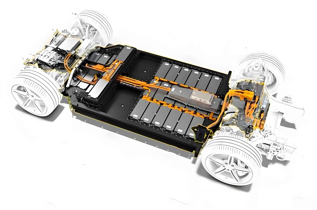
To quantify the electrical capabilities of our developed test equipment, we have summarized the key specifications in the table below. This equipment supports high-voltage and high-power testing, essential for modern electric drive systems in vehicles.
| Category | Parameter |
|---|---|
| High-voltage supply | Up to 1000 V |
| Low-voltage supply | 9–200 V |
| Rated current | 500 A |
| Bench power | 220 kW |
| Maximum speed | 7000 rpm |
| Maximum torque | 1000 N·m |
Under operational conditions—such as 7000 rpm and 150 A—the radiation emissions inside the anechoic chamber were measured and compared against the Class 5 limits of GB/T 18655-2018. The results showed emissions more than 20 dB below the limits across all frequency bands, confirming the equipment’s compliance. This validation underscores the effectiveness of our EMC-focused design, enabling reliable testing of the electric drive system under load without external interference.
Moving beyond hardware, the second pillar of our closed-loop approach involves establishing a simulation platform for conducting EMI analysis under load. This platform is crucial for predictive design, allowing us to model and optimize the electric drive system’s EMC performance before physical prototyping. The simulation model encompasses all critical components of the electric drive system, including the IGBT power module, high-voltage line impedance stabilization network (LISN), DC and AC cables, bus capacitors, copper busbars, and the motor itself. Additionally, it integrates control algorithms and load characteristics to emulate real-world operation. The model structure is designed to align with standard test setups, focusing on conducted emissions from the high-voltage side, which are often a major source of compliance issues.
A key aspect of this simulation is accurately modeling the electric drive system’s motor under load. For a permanent magnet synchronous motor (PMSM)—commonly used in electric vehicles—the electromagnetic torque is governed by the equation:
$$ T_{em} = p \left[ \phi_f i_q + (L_d – L_q) i_d i_q \right] $$
where \( T_{em} \) is the electromagnetic torque, \( p \) is the number of pole pairs, \( \phi_f \) is the permanent magnet flux linkage, \( i_d \) and \( i_q \) are the direct and quadrature axis currents, and \( L_d \) and \( L_q \) are the corresponding inductances. To obtain these parameters under various operating conditions, we performed three-dimensional electromagnetic simulations of the motor geometry. The model included detailed representations of the stator, rotor, and windings, with boundary conditions set to extract characteristics like inductance and flux linkage across speed and torque ranges. This data was then used to create a load model that replicates the motor’s behavior under maximum torque per ampere control, ensuring realistic simulation of on-load scenarios.
For example, at a condition of 3000 rpm and 100 N·m torque, the simulation achieved stable speed and torque outputs, as shown in the performance curves. This load model was integrated into the overall electric drive system EMI model, which was simulated using a time-domain solver with a step size of 2 ns to capture high-frequency switching effects. The output was processed through an EMI receiver model with bandwidths and step sizes per GB/T 18655-2018 (e.g., 9 kHz RBW for 150 kHz–30 MHz). Validation against physical measurements at 3000 rpm and 50 N·m showed good agreement: in the 150 kHz–20 MHz range, the simulated conducted emission spectra matched the test data in terms of resonant peaks and trends, with amplitude errors generally within 6 dBμV. This confirms the accuracy of our simulation platform for predicting EMI behavior.
With a validated model, we proceeded to analyze the impact of key parasitic parameters on the electric drive system’s conducted EMI. Parasitic elements, such as inductances and capacitances within the IGBT module, play a significant role in EMI propagation. For instance, the parasitic inductance at the IGBT gate and the parasitic capacitance between the IGBT and heat sink are critical. We conducted parametric studies by varying these values in the simulation. When the gate parasitic inductance was increased from 1 nH to 10 nH, the conducted emissions in the 2–30 MHz range rose significantly, with resonant peaks shifting to lower frequencies. This highlights the importance of minimizing this inductance through careful packaging design, as it affects switching speeds and ringing. Similarly, increasing the IGBT-to-heat-sink capacitance from 796.5 pF to 1796.5 pF led to higher emissions in the 150 kHz–8 MHz band, due to reduced common-mode impedance, making it easier for interference to escape. These insights emphasize that controlling such parasitics is essential for EMC optimization in the electric drive system.
Another avenue for optimization is through pulse-width modulation (PWM) control strategies. Electric drive systems typically use space vector PWM (SVPWM) for its efficiency. We explored alternative methods like discontinuous PWM (DPWM) to assess their EMI reduction potential. Switching to DPWM3 showed minimal change, with only about 2 dBμV reduction in emissions from 200 kHz to 2 MHz. However, DPWMmin demonstrated more substantial improvements: overall conducted emission levels dropped, with an 8 dBμV reduction at the 8 MHz resonant peak. This suggests that tailored PWM schemes can mitigate EMI without compromising performance, offering a software-based optimization lever for the electric drive system. The table below summarizes the effects of these parameter variations on conducted emissions, based on our simulation results.
| Parameter Variation | Impact on Conducted EMI | Key Frequency Range |
|---|---|---|
| Gate parasitic inductance increase (1 nH to 10 nH) | Increased emissions, resonant shift lower | 2–30 MHz |
| IGBT-to-heat-sink capacitance increase (796.5 pF to 1796.5 pF) | Increased emissions | 150 kHz–8 MHz |
| PWM change: SVPWM to DPWM3 | Minor reduction (~2 dBμV) | 200 kHz–2 MHz |
| PWM change: SVPWM to DPWMmin | Significant reduction (up to 8 dBμV) | Peak at 8 MHz |
The integration of test equipment and simulation forms a closed-loop system for EMC development. In practice, we use the test equipment to gather empirical data on the electric drive system’s emissions under load, which feeds back into the simulation model for refinement. Conversely, simulation predictions guide design modifications that are then validated on the test bench. This iterative process ensures continuous improvement and compliance from early design stages to production. For example, after identifying high EMI from a prototype electric drive system via testing, we used the simulation to pinpoint parasitic capacitances as the culprit, redesigned the IGBT module layout to reduce them, and verified the improvement through retesting. Such cycles reduce trial-and-error, saving time and resources.
Looking broader, the electric drive system’s EMC is influenced by systemic factors like cable routing, grounding strategies, and filter design. Our simulation platform allows for exploring these aspects virtually. We modeled the entire high-voltage harness, including its impedance and coupling effects, to assess differential-mode and common-mode noise. Filters were designed using component values derived from impedance analyses, with transfer functions calculated to attenuate critical frequencies. The effectiveness of these filters was simulated before implementation, ensuring they meet standards without over-engineering. This holistic approach extends beyond the electric drive system itself to include interactions with other vehicle systems, providing a comprehensive EMC assessment framework.
In conclusion, the closed-loop development methodology presented here offers a robust solution for managing electromagnetic compatibility in electric drive systems for new energy vehicles. By combining advanced test equipment that accurately replicates load conditions with a high-fidelity simulation platform, we can predict, analyze, and optimize EMC performance throughout the development lifecycle. Key findings include the critical role of parasitic parameters in IGBT modules, the potential of PWM control strategies for EMI reduction, and the importance of shielding and grounding in test equipment design. This integrated approach not only ensures compliance with stringent standards like GB/T 18655-2018 but also enhances the reliability and safety of electric vehicles. As the automotive industry shifts toward electrification, such methodologies will become indispensable for developing efficient and interference-free electric drive systems, paving the way for wider adoption of sustainable transportation.