
In recent years, the rapid development of battery electric vehicles has brought about significant advancements in autonomous driving technologies. As a core component of autonomous systems, trajectory tracking aims to minimize deviations between the actual path of a vehicle and the desired trajectory by controlling lateral motion. However, under extreme conditions such as high speeds or low-adhesion roads, traditional control methods often struggle to maintain both tracking accuracy and vehicle stability due to tire nonlinearities and dynamic complexities. In this article, we propose a coordinated control strategy that integrates trajectory tracking with direct yaw moment control, optimized using a Genetic Firefly Algorithm (G-FA), to enhance the performance of battery electric vehicles. Our approach leverages a Linear Quadratic Regulator (LQR) for trajectory tracking, augmented with feedforward control and a fuzzy PID controller for stability, with key parameters tuned via G-FA. Through CarSim/Simulink co-simulations, we demonstrate substantial improvements in tracking errors and stability indicators, underscoring the efficacy of our method for battery electric vehicles in challenging scenarios.
The proliferation of battery electric vehicles has intensified research into intelligent control systems, particularly for trajectory tracking, which is crucial for safe and efficient autonomous navigation. Traditional controllers, such as PID or basic LQR, often rely on fixed parameters that are manually tuned, leading to suboptimal performance under varying conditions. Moreover, while Model Predictive Control (MPC) offers robustness, its computational burden can hinder real-time application in battery electric vehicles. To address these limitations, we introduce a hybrid algorithm—G-FA—that combines the global search capabilities of genetic algorithms with the local refinement of firefly algorithms, enabling adaptive optimization of controller parameters. This article details our modeling framework, control design, and simulation results, highlighting the synergy between trajectory tracking and stability enhancement for battery electric vehicles.
Our contributions are threefold: First, we establish a comprehensive vehicle dynamics model and tracking error model tailored for battery electric vehicles. Second, we develop an LQR-based trajectory tracking controller with feedforward compensation, optimized offline using G-FA to eliminate steady-state errors. Third, we incorporate a fuzzy PID direct yaw moment controller to maintain vehicle stability, ensuring robust performance in double lane-change and S-shaped curve maneuvers. The subsequent sections elaborate on these aspects, supported by mathematical formulations, tables, and simulation data, all aimed at advancing the control paradigms for battery electric vehicles.
Vehicle Dynamics and Error Modeling
To formulate the control problem, we begin by deriving a simplified vehicle model that captures the essential lateral and yaw motions of a battery electric vehicle. Assuming constant longitudinal velocity and neglecting vertical dynamics, we consider a two-degree-of-freedom bicycle model, which is widely used for control design in battery electric vehicles due to its balance between accuracy and simplicity. The model equations are as follows:
The lateral force and yaw moment balances yield:
$$(k_1 + k_2) \beta + \frac{1}{u}(a k_1 – b k_2) \omega_r – k_1 \delta = m(\dot{v} + u \omega_r)$$
$$(a k_1 – b k_2) \beta + \frac{1}{u}(a^2 k_1 + b^2 k_2) \omega_r – a k_1 \delta = I_z \dot{\omega}_r$$
where \(k_1\) and \(k_2\) are the cornering stiffnesses of the front and rear axles, \(\beta\) is the sideslip angle, \(u\) and \(v\) are the longitudinal and lateral velocities, \(a\) and \(b\) are distances from the center of mass to the front and rear axles, \(\omega_r\) is the yaw rate, \(\delta\) is the front wheel steering angle, \(m\) is the mass of the battery electric vehicle, and \(I_z\) is the moment of inertia about the vertical axis.
Defining the state vector \(\xi = [v, \omega_r]^T\) and control input \(U = \delta\), we express the state-space representation:
$$\dot{\xi} = A_c \xi + B_c U$$
with:
$$A_c = \begin{bmatrix} \frac{k_1 + k_2}{m u} & \frac{a k_1 – b k_2}{m u} – u \\ \frac{a k_1 – b k_2}{I_z u} & \frac{a^2 k_1 + b^2 k_2}{I_z u} \end{bmatrix}, \quad B_c = \begin{bmatrix} -\frac{k_1}{m} \\ -\frac{a k_1}{I_z} \end{bmatrix}$$
This model serves as the ideal reference for our battery electric vehicle, providing baseline dynamics against which tracking performance is evaluated.
Next, we develop a trajectory tracking error model to quantify deviations from a desired path. Let \(e_d\) denote the lateral error (distance from the vehicle’s center of mass to the projected point on the reference trajectory), and \(e_\phi\) represent the heading error (difference between the vehicle’s yaw angle \(\phi\) and the reference yaw angle \(\theta_r\)). Assuming small sideslip angles, we approximate \(e_\phi \approx \phi – \theta_r\). The error dynamics are derived as:
$$\dot{e}_d = u e_\phi + v$$
$$\dot{e}_\phi = \dot{\phi} – \dot{\theta}_r$$
By differentiating and substituting the vehicle model, we obtain the error state equation:
$$\dot{e}_{rr} = A e_{rr} + B U + C \dot{\theta}_r$$
where \(e_{rr} = [e_d, \dot{e}_d, e_\phi, \dot{e}_\phi]^T\) is the error state vector, and matrices \(A\), \(B\), and \(C\) are defined as:
$$A = \begin{bmatrix} 0 & 1 & 0 & 0 \\ 0 & \frac{k_1 + k_2}{m u} & -\frac{k_1 + k_2}{m} & \frac{k_1 a – k_2 b}{m u} \\ 0 & 0 & 0 & 1 \\ 0 & \frac{a k_1 – b k_2}{I_z u} & -\frac{a k_1 – b k_2}{I_z} & \frac{a^2 k_1 + b^2 k_2}{I_z u} \end{bmatrix}, \quad B = \begin{bmatrix} 0 \\ -\frac{k_1}{m} \\ 0 \\ -\frac{a k_1}{I_z} \end{bmatrix}, \quad C = \begin{bmatrix} 0 \\ \frac{k_1 a – k_2 b}{m u} – u \\ 0 \\ \frac{a^2 k_1 + b^2 k_2}{I_z u} \end{bmatrix}$$
This formulation encapsulates the tracking challenges for battery electric vehicles, setting the stage for controller design.
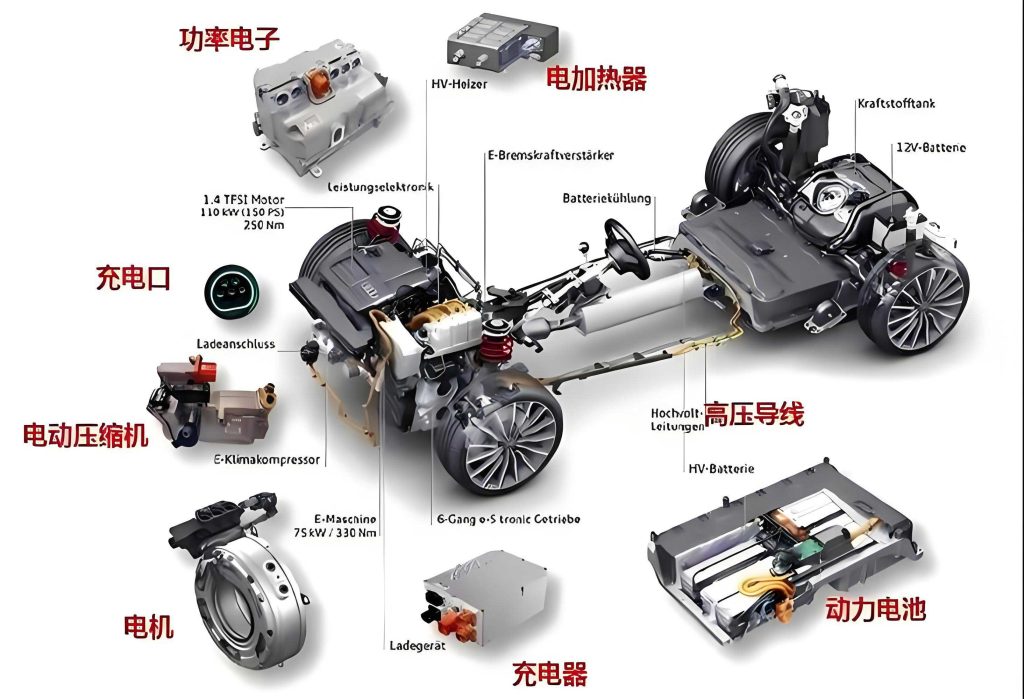
Control Strategy Development
Our control architecture for battery electric vehicles integrates two main components: a trajectory tracking controller based on LQR with G-FA optimization, and a stability controller using fuzzy PID for direct yaw moment control. The synergy between these modules ensures precise path following while maintaining vehicle integrity under dynamic stresses.
LQR Trajectory Tracking with G-FA Optimization
The LQR controller aims to minimize a quadratic cost function that penalizes tracking errors and control efforts. For our battery electric vehicle, we define the cost function as:
$$J = \frac{1}{2} \int_0^\infty \left( e_{rr}^T Q e_{rr} + U^T R U \right) dt$$
where \(Q\) and \(R\) are weighting matrices that balance state deviations and input usage. Typically, \(Q\) is diagonal with elements corresponding to the importance of each error state, and \(R\) is a scalar or matrix reflecting control input costs. The optimal control law is given by:
$$\Delta U(t) = -K e_{rr}(t)$$
with feedback gain \(K = R^{-1} B^T P\), where \(P\) solves the algebraic Riccati equation:
$$P A + A^T P – P B R^{-1} B^T P + Q = 0$$
However, fixed \(Q\) and \(R\) matrices often lead to suboptimal performance across diverse operating conditions for battery electric vehicles. To address this, we employ the Genetic Firefly Algorithm (G-FA) to optimize \(Q\), specifically focusing on the weights associated with lateral and heading errors. G-FA merges the evolutionary operations of genetic algorithms (selection, crossover, mutation) with the attraction-based movement of firefly algorithms, enhancing global search efficiency and local convergence.
The optimization process involves encoding \(Q\) parameters as chromosomes, evaluating fitness based on tracking error metrics, and iteratively updating solutions. We define the fitness function as:
$$F = w_1 |\bar{e}_d| + w_2 |\bar{e}_\phi|$$
where \(w_1 = 0.6\) and \(w_2 = 0.4\) are weighting coefficients, and \(|\bar{e}_d|\) and \(|\bar{e}_\phi|\) are average absolute lateral and heading errors from simulations. The G-FA steps include:
- Initialization: Generate a population of \(Q\) matrices with random values within bounds.
- Fitness Evaluation: Simulate the battery electric vehicle model under test conditions to compute \(F\).
- Genetic Operations: Apply selection, crossover, and mutation to create offspring populations.
- Firefly Movement: Update solutions based on attractiveness and distance, using the update rule:
$$X_i^{t+1} = X_i^t + \beta_0 e^{-\gamma r_{ij}^2}(X_j^t – X_i^t) + \alpha^t (\text{rand} – 0.5)$$
where \(X_i\) represents a solution vector, \(\beta_0 = 0\) is the attractiveness at zero distance, \(\gamma = 0.33\) is the light absorption coefficient, and \(\alpha = 0.9\) controls randomization. - Termination: Repeat until convergence or a maximum iteration count is reached.
Through offline optimization for specific scenarios (e.g., double lane-change at 80 km/h), we obtain optimal \(Q\) matrices that are then interpolated for real-time application in battery electric vehicles. This adaptive tuning significantly improves tracking precision.
Additionally, to eliminate steady-state errors, we incorporate a feedforward control term \(\delta_f\) derived from the steady-state analysis of the error dynamics. The combined control input becomes:
$$U = -K e_{rr} + \delta_f$$
where \(\delta_f\) is calculated as:
$$\delta_f = \rho \left[ a + b – b K_3 – \frac{m u^2}{a + b} \left( \frac{b}{k_1} + \frac{a}{k_2} K_3 – \frac{a}{k_2} \right) \right]$$
with \(\rho\) being the path curvature and \(K_3\) the third element of the feedback gain \(K\). This feedforward component compensates for inherent system biases, enhancing the responsiveness of battery electric vehicles to curved paths.
Fuzzy PID Direct Yaw Moment Control for Stability
While trajectory tracking focuses on spatial accuracy, vehicle stability—particularly yaw and sideslip behavior—is critical for safety in battery electric vehicles. We design a fuzzy PID controller to compute an additional yaw moment \(\Delta M\) that corrects deviations from ideal dynamics. The control structure compares actual vehicle states (sideslip angle \(\beta\) and yaw rate \(\omega_r\)) with reference values from the ideal model, generating \(\Delta M\) to restore stability.
The reference sideslip angle \(\beta_d\) is derived from the steady-state response of the bicycle model, adjusted for road adhesion limits:
$$\beta_d = \min \left( \frac{b + \frac{m a u^2}{k_2 L}}{L(1 + K u^2)} \delta, \left| \frac{\mu g (b u^2 + m a)}{k_2 L} \right| \cdot \text{sgn}(\cdot) \right)$$
where \(L = a + b\), \(K = \frac{m}{L^2} \left( \frac{a}{k_2} – \frac{b}{k_1} \right)\) is the stability factor, \(\mu\) is the road adhesion coefficient, and \(g\) is gravitational acceleration. This ensures physically feasible references for battery electric vehicles.
The fuzzy PID controller uses error \(e_\beta = \beta – \beta_d\) and its derivative \(\dot{e}_\beta\) as inputs, dynamically adjusting proportional, integral, and derivative gains (\(k_p\), \(k_i\), \(k_d\)) through fuzzy inference. The output yaw moment is:
$$\Delta M(t) = k_p e_\beta(t) + k_i \int_0^t e_\beta(\tau) d\tau + k_d \frac{d e_\beta(t)}{dt}$$
We define fuzzy sets (e.g., Negative, Zero, Positive) and rules (e.g., IF \(e_\beta\) is Positive AND \(\dot{e}_\beta\) is Negative THEN \(k_p\) is High) to encapsulate expert knowledge. This adaptive approach allows the controller to mitigate oversteer or understeer in battery electric vehicles, especially during aggressive maneuvers.
Simulation Results and Analysis
We validate our coordinated control strategy using CarSim/Simulink co-simulations for a battery electric vehicle with parameters listed in Table 1. Two test scenarios are considered: a double lane-change maneuver at 80 km/h on a road with adhesion coefficient 0.7, and an S-shaped curve at 60 km/h with adhesion coefficient 0.6. We compare three controllers: the original LQR (baseline), G-FA optimized LQR (G-FA-LQR), and our full coordinated controller (G-FA-LQR-DYC). Performance metrics include lateral error \(e_d\), heading error \(e_\phi\), sideslip angle \(\beta\), and yaw rate \(\omega_r\), with results summarized in tables and discussed below.
| Parameter | Symbol | Value |
|---|---|---|
| Vehicle mass | \(m\) | 1412 kg |
| Distance from CoG to front axle | \(a\) | 1.015 m |
| Distance from CoG to rear axle | \(b\) | 1.895 m |
| Front axle cornering stiffness | \(k_1\) | -110 kN/rad |
| Rear axle cornering stiffness | \(k_2\) | -110 kN/rad |
| Yaw moment of inertia | \(I_z\) | 1536.7 kg·m² |
| Wheel effective radius | \(r\) | 0.325 m |
The double lane-change results, as shown in Figure 1 (though not referenced directly), indicate that our G-FA-LQR-DYC controller achieves the closest tracking to the reference trajectory, particularly in high-curvature sections. Quantitative improvements are evident in Table 2, which compiles peak and root-mean-square (RMS) values for key metrics. For instance, lateral error peaks drop by 32.14% compared to the original LQR, highlighting the efficacy of G-FA optimization in battery electric vehicles. Moreover, the integration of direct yaw moment control reduces sideslip angle peaks by 25.61%, underscoring enhanced stability.
| Metric | Original LQR | G-FA-LQR | G-FA-LQR-DYC |
|---|---|---|---|
| Lateral error peak (m) | 0.5508 | 0.3806 | 0.3738 |
| Lateral error RMS (m) | 0.2066 | 0.1731 | 0.1574 |
| Heading error peak (rad) | 0.0901 | 0.0874 | 0.0664 |
| Heading error RMS (rad) | 0.0396 | 0.0361 | 0.0326 |
| Sideslip angle peak (rad) | 0.0898 | 0.0818 | 0.0668 |
| Sideslip angle RMS (rad) | 0.0363 | 0.0313 | 0.0274 |
| Yaw rate peak (rad/s) | 0.5549 | 0.5296 | 0.5132 |
| Yaw rate RMS (rad/s) | 0.2912 | 0.2542 | 0.2449 |
Similarly, for the S-shaped curve scenario, Table 3 presents comparative data. Our coordinated controller reduces lateral error peaks by 60.28% relative to the baseline, demonstrating robust tracking in complex paths for battery electric vehicles. The sideslip angle and yaw rate are also better contained, with reductions of 10.34% and 9.49% in peaks, respectively, affirming the stability benefits of fuzzy PID intervention.
| Metric | Original LQR | G-FA-LQR | G-FA-LQR-DYC |
|---|---|---|---|
| Lateral error peak (m) | 0.6843 | 0.6733 | 0.2718 |
| Lateral error RMS (m) | 0.4895 | 0.4907 | 0.2183 |
| Heading error peak (rad) | 0.0460 | 0.0437 | 0.0426 |
| Heading error RMS (rad) | 0.0338 | 0.0290 | 0.0273 |
| Sideslip angle peak (rad) | 0.0174 | 0.0161 | 0.0156 |
| Sideslip angle RMS (rad) | 0.0054 | 0.0049 | 0.0045 |
| Yaw rate peak (rad/s) | 0.3646 | 0.3380 | 0.3300 |
| Yaw rate RMS (rad/s) | 0.2776 | 0.2767 | 0.2728 |
To further illustrate the control effects, we analyze the time-domain responses of key variables. For example, the lateral error \(e_d(t)\) under G-FA-LQR-DYC converges faster and with smaller oscillations, as described by the differential equation from our error model. The yaw moment \(\Delta M(t)\) generated by the fuzzy PID controller can be expressed as a function of error dynamics, contributing to stability. These results collectively validate that our approach significantly enhances both tracking accuracy and vehicle stability for battery electric vehicles, making it suitable for real-world autonomous applications.
Mathematical Insights and Formulations
Underpinning our simulations are detailed mathematical models that govern the behavior of battery electric vehicles. The LQR controller’s optimal gain matrix \(K\) is computed via the Riccati equation, which for our system yields a unique positive-definite solution \(P\) given appropriate \(Q\) and \(R\). The G-FA optimization alters \(Q\) iteratively, with each candidate evaluated through numerical integration of the vehicle dynamics. For instance, the state trajectory under control input \(U\) is obtained by solving:
$$\dot{x} = f(x, U)$$
where \(x\) includes vehicle states and errors. The fitness evaluation involves simulating this ODE system over the maneuver duration.
Moreover, the fuzzy PID controller’s output \(\Delta M\) influences the yaw dynamics by modifying the moment balance. The augmented yaw equation becomes:
$$I_z \dot{\omega}_r = \Delta M + (a k_1 – b k_2) \beta + \frac{1}{u}(a^2 k_1 + b^2 k_2) \omega_r – a k_1 \delta$$
This integration ensures that stability corrections are consistent with the physical constraints of battery electric vehicles. The fuzzy rules are designed based on phase-plane analysis of \(\beta\) and \(\omega_r\), where stable regions are identified to prevent rollover or skidding.
We also derive sensitivity analyses to parameter variations, such as changes in cornering stiffness due to tire wear or road conditions. For a battery electric vehicle, these variations can be accommodated by the adaptive nature of G-FA and fuzzy logic, as opposed to fixed-gain controllers. The robustness of our method is thus mathematically grounded in its ability to adjust to nonlinearities and uncertainties.
Conclusion and Future Directions
In this article, we have presented a coordinated control strategy for battery electric vehicles that combines G-FA optimized LQR trajectory tracking with fuzzy PID direct yaw moment control. Our methodology addresses the dual challenges of path accuracy and dynamic stability, which are paramount for autonomous battery electric vehicles operating in extreme conditions. Through comprehensive modeling and CarSim/Simulink simulations, we demonstrated substantial reductions in lateral error, heading error, sideslip angle, and yaw rate across double lane-change and S-shaped curve scenarios. These improvements underscore the potential of hybrid optimization algorithms and intelligent control systems for enhancing the performance of battery electric vehicles.
Looking ahead, several avenues warrant further exploration. First, real-time implementation of G-FA optimization could be investigated using edge computing platforms to enable online parameter tuning for battery electric vehicles. Second, incorporating roll dynamics and active suspension control may extend stability benefits to three-dimensional vehicle behavior. Third, validation with hardware-in-the-loop experiments or field tests on actual battery electric vehicles would strengthen the practical relevance of our approach. Lastly, integrating vehicle-to-everything (V2X) communications could allow predictive adjustments based on road preview, further advancing autonomous capabilities for battery electric vehicles.
Overall, our work contributes to the evolving landscape of intelligent vehicle control, offering a scalable and effective solution for battery electric vehicles. By leveraging advanced algorithms like G-FA and fuzzy logic, we pave the way for safer, more efficient, and more responsive autonomous driving experiences in battery electric vehicles.