
As the adoption of battery electric cars accelerates globally, the infrastructure supporting these vehicles, particularly charging systems, has become a critical focus. In this article, I will delve into the testing and evaluation framework for charging interfaces used in battery electric cars. These interfaces, including connectors and sockets for both direct current (DC) and alternating current (AC) charging, are essential for safe and efficient energy replenishment. With battery electric cars becoming more prevalent in diverse environments—from urban settings to extreme climates—ensuring the reliability, safety, and durability of charging interfaces is paramount. I aim to provide an in-depth exploration of the key testing methodologies, covering electrical safety, mechanical robustness, and environmental resilience, all tailored to the unique demands of battery electric cars. By incorporating tables and formulas, I will summarize complex concepts, emphasizing the importance of rigorous standards to enhance user trust and operational efficiency in the era of battery electric cars.
The charging interface for a battery electric car serves as the physical and electrical bridge between the vehicle and the charging infrastructure. It facilitates the transfer of energy, data signals, and safety protocols during conductive charging. For battery electric cars, the interface must handle high voltages and currents, often under varying conditions, making comprehensive testing indispensable. I will begin by outlining the types of charging interfaces, followed by a detailed breakdown of testing parameters, referencing international standards while avoiding specific names or locations. Throughout this discussion, I will consistently highlight the relevance to battery electric cars, as their widespread use drives the need for robust evaluation systems. The integration of advanced testing not only mitigates risks like electrical faults or mechanical failures but also supports the scalability of battery electric car networks, ensuring seamless charging experiences for users worldwide.
Types of Charging Interfaces for Battery Electric Cars
Charging interfaces for battery electric cars can be categorized based on their electrical configuration and cooling mechanisms. Primarily, they include DC charging interfaces, AC charging interfaces, and combined AC/DC interfaces. DC interfaces are designed for fast charging, typically operating at higher voltages and currents, which is crucial for reducing downtime in battery electric cars. AC interfaces, on the other hand, are used for slower, often overnight charging, common in residential settings for battery electric cars. Additionally, interfaces may incorporate air-cooling or liquid-cooling systems to manage heat generated during high-power charging, especially in battery electric cars that support rapid charging protocols. The physical layout involves multiple contacts for power, grounding, communication, and control, as illustrated in the following table summarizing key contacts for DC and AC interfaces in battery electric cars.
| Interface Type | Contact Symbol | Function | Relevance to Battery Electric Cars |
|---|---|---|---|
| DC Charging Interface | DC+, DC- | Positive and negative DC power terminals for direct energy transfer to the battery pack in battery electric cars. | Enables high-speed charging, reducing wait times for battery electric car users. |
| DC Charging Interface | PE | Protective earth terminal for safety grounding, preventing electric shock in battery electric cars. | Critical for user safety during high-voltage charging of battery electric cars. |
| DC Charging Interface | CC1, CC2 | Charging connection confirmation contacts for handshake protocols between the charger and battery electric car. | Ensures secure coupling before energizing, vital for battery electric car system integrity. |
| DC Charging Interface | S+, S- | Communication contacts (e.g., CAN bus) for data exchange during charging of battery electric cars. | Facilitates real-time monitoring and control, optimizing charging for battery electric car batteries. |
| AC Charging Interface | L1, L2, L3 | AC power lines for single or three-phase supply to the onboard charger of battery electric cars. | Supports flexible charging from grid sources, common for home charging of battery electric cars. |
| AC Charging Interface | N | Neutral line in AC systems, completing the circuit for battery electric car charging. | Essential for stable AC power delivery to battery electric cars. |
| AC Charging Interface | CP | Control pilot contact for signaling and safety checks in battery electric car charging. | Prevents unauthorized access and ensures compatibility for battery electric cars. |
Understanding these configurations is fundamental for testing, as each contact must meet specific performance criteria to ensure reliable operation in battery electric cars. The design evolution, driven by the growth of battery electric cars, has led to standardized interfaces that balance power delivery and safety. For instance, DC interfaces in battery electric cars often operate at voltages up to 1000 V or more, necessitating rigorous insulation and thermal management tests. Similarly, AC interfaces for battery electric cars must accommodate varying grid conditions while maintaining user-friendly features. As battery electric cars diversify into different models and use cases, the charging interface testing must adapt, emphasizing scalability and interoperability to support the global battery electric car ecosystem.
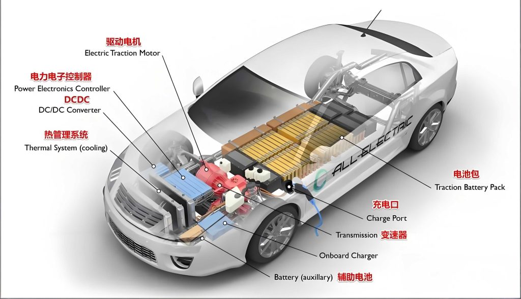
Electrical Safety Performance Testing for Battery Electric Car Charging Interfaces
Electrical safety is paramount for charging interfaces in battery electric cars, given the high voltages and currents involved. Testing focuses on preventing hazards such as electric shock, short circuits, and thermal runaway, which could compromise battery electric car systems. I will outline key test categories, incorporating formulas to quantify performance metrics. For battery electric cars, these tests ensure that charging interfaces can withstand operational stresses without degrading safety.
First, grounding measures are evaluated to verify low-resistance paths for fault currents. This is crucial for battery electric cars to protect users from leakage currents. The test involves applying a high current to the earth terminal and measuring voltage drop, ensuring compliance with standards. The resistance $$ R_{earth} $$ should satisfy $$ R_{earth} \leq \frac{V_{max}}{I_{test}} $$, where $$ V_{max} $$ is the allowable voltage limit and $$ I_{test} $$ is the test current, typically derived from ratings specific to battery electric car interfaces.
Insulation resistance and dielectric strength tests assess the integrity of insulating materials in charging interfaces for battery electric cars. A high voltage is applied between conductive parts, and leakage current is measured. The insulation resistance $$ R_{ins} $$ must exceed a threshold, often calculated as $$ R_{ins} \geq \frac{V_{rated}}{I_{leakage}} $$, where $$ V_{rated} $$ is the rated voltage of the battery electric car charging system. For dielectric strength, the interface must withstand a test voltage without breakdown, ensuring safety during surges in battery electric car charging.
Temperature rise testing is critical for battery electric car charging interfaces, as excessive heat can lead to component failure or fire. The test simulates continuous charging at rated current, monitoring temperature increases at key points. The steady-state temperature rise $$ \Delta T $$ is given by $$ \Delta T = \frac{P \cdot t}{m \cdot c} $$, where $$ P $$ is the power loss ($$ I^2 R $$), $$ t $$ is time, $$ m $$ is mass, and $$ c $$ is specific heat capacity. For battery electric cars, limits are set to prevent degradation; for example, a rise exceeding 50 K might indicate poor design. The table below summarizes key electrical safety tests for battery electric car charging interfaces.
| Test Item | Objective | Test Method | Key Formula/Requirement | Relevance to Battery Electric Cars |
|---|---|---|---|---|
| Grounding Measures | Ensure effective earth connection for fault protection. | Apply test current to earth terminal; measure resistance. | $$ R_{earth} \leq 0.1 \Omega $$ for high-current battery electric car interfaces. | Prevents electric shock in battery electric cars during charging faults. |
| Insulation Resistance | Verify insulation integrity between live parts. | Apply DC voltage; measure leakage current. | $$ R_{ins} \geq 1 M\Omega $$ at 500 V for battery electric car systems. | Ensures isolation in high-voltage battery electric car circuits. |
| Dielectric Strength | Assess ability to withstand high voltage without breakdown. | Apply AC or DC test voltage for a duration. | Withstand $$ 2 \cdot V_{rated} + 1000 V $$ for 60 s in battery electric car interfaces. | Protects against transient surges in battery electric car charging. |
| Temperature Rise | Monitor heating under continuous load. | Operate at rated current until thermal stability. | $$ \Delta T \leq 50 K $$ for contacts in battery electric car charging. | Prevents overheating and ensures longevity of battery electric car components. |
| Short-Circuit Withstand | Evaluate tolerance to fault currents. | Apply limited short-circuit current; check for damage. | Current based on cable cross-section: $$ I_{sc} = k \cdot A $$, where $$ A $$ is area. | Safeguards battery electric car interfaces during electrical faults. |
| Terminal and Endurance | Test electrical continuity under current cycling. | Cycle current on/off; measure resistance changes. | Resistance change $$ \Delta R \leq 10\% $$ after 240 cycles for battery electric car terminals. | Ensures reliable connections in frequent charging of battery electric cars. |
For battery electric cars, additional tests include verification of thermal management systems, especially in liquid-cooled interfaces. The cooling efficiency can be modeled using heat transfer equations, such as $$ Q = h \cdot A \cdot \Delta T $$, where $$ Q $$ is heat dissipated, $$ h $$ is heat transfer coefficient, and $$ A $$ is surface area. This ensures that battery electric car charging interfaces maintain safe temperatures during high-power sessions. Moreover, temperature monitoring functionality is tested by heating contacts to 95°C and validating sensor accuracy, critical for preventing thermal issues in battery electric cars. By adhering to these electrical safety protocols, manufacturers can guarantee that charging interfaces for battery electric cars minimize risks, enhancing user confidence in the technology.
Mechanical Reliability Performance Testing for Battery Electric Car Charging Interfaces
Mechanical reliability ensures that charging interfaces for battery electric cars withstand physical stresses from repeated use, environmental exposure, and accidental impacts. Given that battery electric cars are often charged daily in various settings, interfaces must endure thousands of mating cycles without failure. I will detail key mechanical tests, using formulas to analyze forces and durability, emphasizing their importance for battery electric car applications.
Insertion and withdrawal force testing evaluates the ease of connecting and disconnecting charging interfaces for battery electric cars. Excessive force can strain users or damage components. The force $$ F $$ required should satisfy $$ F_{insert} \leq 100 , \text{N} $$ and $$ F_{withdraw} \leq 140 , \text{N} $$ for standard interfaces in battery electric cars. This is measured using force gauges during simulated plugging, ensuring user-friendly operation for battery electric car owners.
Mechanical locking device testing assesses the reliability of latches that secure the connection in battery electric cars. These devices prevent accidental disconnection during charging. The test involves applying a weight to the locked interface and verifying it remains engaged for 60 seconds. For battery electric cars, the locking force $$ F_{lock} $$ must exceed the gravitational force of the weight, calculated as $$ F_{lock} > m \cdot g $$, where $$ m $$ is mass and $$ g $$ is acceleration due to gravity. Durability is also tested through cycling; mechanical locks must survive 10,000 mating cycles, while electronic locks in advanced battery electric car interfaces require 20,000 cycles, with periodic checks of emergency release mechanisms.
Impact and crushing resistance tests simulate real-world abuses, such as dropping or vehicle run-over scenarios for battery electric car charging cables. The impact test uses a pendulum to strike the interface, with energy calculated as $$ E = m \cdot g \cdot h $$, where $$ h $$ is drop height. For run-over tests, a tire applies force $$ F_{tire} = 5000 , \text{N} $$ at speed $$ v = 8 , \text{km/h} $$, mimicking accidental driving over a cable for battery electric cars. Interfaces must remain functional post-test, ensuring safety in diverse environments where battery electric cars are charged.
Durability under offset loading evaluates the interface’s tolerance to misalignment during use in battery electric cars. A force of 100 N is applied in lateral directions for 1 minute, and the interface is checked for integrity. The stress $$ \sigma $$ can be estimated as $$ \sigma = \frac{F}{A} $$, where $$ A $$ is the cross-sectional area, ensuring it remains below material yield strength for battery electric car components. After testing, temperature rise must not increase by more than 10 K, maintaining performance for battery electric car charging.
The table below summarizes mechanical reliability tests for battery electric car charging interfaces, highlighting key parameters and requirements.
| Test Item | Objective | Test Method | Key Formula/Requirement | Relevance to Battery Electric Cars |
|---|---|---|---|---|
| Insertion/Withdrawal Force | Ensure ease of use and prevent damage. | Measure force during plugging/unplugging cycles. | $$ F \leq 100 , \text{N} $$ (insert), $$ \leq 140 , \text{N} $$ (withdraw) for battery electric car interfaces. | Enhances user experience for frequent charging of battery electric cars. |
| Mechanical Lock Durability | Verify locking mechanism reliability over cycles. | Cycle locking/unlocking; apply weight test. | Withstand 10,000 cycles for mechanical locks in battery electric cars. | Prevents disconnection during charging, critical for battery electric car safety. |
| Impact Resistance | Assess robustness against physical shocks. | Pendulum impact test at specified energy levels. | Energy $$ E \geq 0.5 , \text{J} $$ for battery electric car interfaces. | Protects against accidental drops in battery electric car charging scenarios. |
| Vehicle Run-Over Test | Evaluate crushing resistance from vehicles. | Roll tire over cable at set force and speed. | Force $$ F = 5000 , \text{N} $$, speed $$ v = 8 , \text{km/h} $$ for battery electric car cables. | Ensures durability in parking areas where battery electric cars are charged. |
| Offset Loading | Test tolerance to misalignment forces. | Apply lateral force; check for deformation. | Force $$ F = 100 , \text{N} $$ for 1 min; $$ \Delta T \leq 10 , \text{K} $$ post-test for battery electric cars. | Maintains connection integrity under stress in battery electric car use. |
| Mating Cycle Endurance | Assess long-term wear of contacts. | Perform repeated plugging under current load. | 970 cycles with environmental exposure for battery electric car interfaces. | Extends lifespan for high-usage battery electric car charging stations. |
For battery electric cars, these mechanical tests are complemented by evaluations of cable flexibility and connector material wear. The wear rate $$ W $$ can be modeled as $$ W = k \cdot N \cdot F $$, where $$ k $$ is a material constant, $$ N $$ is cycle count, and $$ F $$ is force, guiding design improvements for battery electric car interfaces. By meeting these mechanical standards, charging interfaces for battery electric cars ensure reliable performance over their lifecycle, reducing maintenance needs and supporting the growing fleet of battery electric cars.
Environmental Reliability Performance Testing for Battery Electric Car Charging Interfaces
Environmental reliability testing ensures that charging interfaces for battery electric cars operate safely and effectively under various climatic and corrosive conditions. Since battery electric cars are used worldwide—from cold regions to coastal areas—interfaces must resist temperature extremes, humidity, salt spray, and other factors. I will describe key environmental tests, using formulas to quantify degradation rates, and emphasize their role in sustaining battery electric car charging infrastructure.
Temperature cycling tests expose interfaces to alternating high and low temperatures, simulating daily or seasonal variations for battery electric cars. The test profile might range from $$ -40^\circ \text{C} $$ to $$ +85^\circ \text{C} $$, with ramp rates and dwell times specified. The thermal stress $$ \sigma_{thermal} $$ can be approximated using the coefficient of thermal expansion: $$ \sigma_{thermal} = E \cdot \alpha \cdot \Delta T $$, where $$ E $$ is Young’s modulus, $$ \alpha $$ is expansion coefficient, and $$ \Delta T $$ is temperature change. For battery electric car interfaces, this test verifies that materials do not crack or delaminate, ensuring longevity.
Damp heat or cyclic humidity tests assess resistance to moisture ingress, which can cause corrosion or electrical leakage in battery electric car charging systems. The test involves cycles of high humidity (e.g., 95% RH) and elevated temperature (e.g., 85°C), following standards like IEC 60068-2-30. The moisture diffusion rate $$ J $$ can be expressed as $$ J = -D \frac{\partial C}{\partial x} $$, where $$ D $$ is diffusivity and $$ C $$ is concentration, guiding material selection for battery electric car interfaces. After testing, insulation resistance and function are verified to ensure safety for battery electric cars.
Salt spray and corrosion tests evaluate performance in saline environments, common near coasts where battery electric cars may be charged. The test exposes interfaces to a salt fog for hours, simulating years of exposure. The corrosion rate $$ r_{corr} $$ can be modeled using Faraday’s law: $$ r_{corr} = \frac{M \cdot I_{corr}}{n \cdot F \cdot \rho} $$, where $$ M $$ is molar mass, $$ I_{corr} $$ is corrosion current, $$ n $$ is electrons transferred, $$ F $$ is Faraday constant, and $$ \rho $$ is density. For battery electric car interfaces, this ensures that metal contacts remain conductive and structurally sound.
Ingress protection (IP) testing determines the interface’s resistance to dust and water, critical for outdoor charging of battery electric cars. The IP rating, such as IP67, indicates protection levels. The test involves exposing the interface to water jets or dust chambers, with performance criteria based on leakage current. For battery electric cars, a high IP rating prevents failures in rain or dusty conditions, enhancing reliability.
Material aging tests assess the degradation of polymers and elastomers used in battery electric car charging interfaces. Accelerated aging is performed at elevated temperatures (e.g., 70°C for rubber, 80°C for thermoplastics) over days. The Arrhenius equation estimates lifetime: $$ L = A \cdot e^{\frac{E_a}{RT}} $$, where $$ L $$ is lifetime, $$ A $$ is pre-exponential factor, $$ E_a $$ is activation energy, $$ R $$ is gas constant, and $$ T $$ is temperature. This helps predict material behavior in real-world battery electric car applications.
The table below summarizes environmental reliability tests for battery electric car charging interfaces, including key parameters and implications.
| Test Item | Objective | Test Method | Key Formula/Requirement | Relevance to Battery Electric Cars |
|---|---|---|---|---|
| Temperature Cycling | Verify performance under thermal shocks. | Cycle between extreme temperatures; monitor function. | Cycles from $$ -40^\circ \text{C} $$ to $$ +85^\circ \text{C} $$ for battery electric car interfaces. | Ensures operation in varying climates where battery electric cars are used. |
| Damp Heat Cyclic | Assess resistance to humidity and condensation. | Expose to high humidity and temperature cycles. | 95% RH at 85°C for 168 h for battery electric car systems. | Prevents moisture-related failures in battery electric car charging. |
| Salt Spray Corrosion | Evaluate corrosion resistance in saline air. | Spray salt solution; inspect for rust or degradation. | Exposure for 96 h per ISO 9227 for battery electric car interfaces. | Protects coastal charging infrastructure for battery electric cars. |
| Ingress Protection (IP) | Test dust and water resistance. | Subject to water/dust ingress per IEC 60529. | IP67 rating (dust-tight, waterproof up to 1 m) for battery electric car interfaces. | Enables outdoor charging reliability for battery electric cars. |
| Material Aging | Assess polymer degradation over time. | Accelerated aging at high temperatures. | 70°C for 10 d (rubber) or 80°C for 7 d (plastics) for battery electric car materials. | Extends service life of battery electric car charging components. |
| UV Radiation Exposure | Evaluate resistance to sunlight degradation. | Expose to UV lamps simulating solar radiation. | Equivalent to 1 year of sun exposure for battery electric car interfaces. | Prevents fading or brittleness in outdoor battery electric car charging stations. |
For battery electric cars, these environmental tests are often combined with operational checks, such as charging performance after exposure. The overall reliability $$ R_{total} $$ can be estimated using a series model: $$ R_{total} = \prod_{i=1}^{n} R_i $$, where $$ R_i $$ is the reliability of each tested aspect, ensuring comprehensive safety for battery electric car systems. By passing these tests, charging interfaces for battery electric cars demonstrate resilience, supporting the expansion of charging networks in diverse regions and promoting the adoption of battery electric cars.
Integration of Testing Systems for Battery Electric Car Charging Interfaces
The integration of electrical, mechanical, and environmental testing forms a holistic evaluation system for battery electric car charging interfaces. This system ensures that interfaces meet the stringent demands of modern battery electric cars, which require fast, safe, and reliable charging across various scenarios. I will discuss how these tests interrelate, using formulas to model combined effects, and highlight the importance of standardized protocols for battery electric car ecosystems.
One key aspect is the synergy between thermal management and mechanical durability in battery electric car charging interfaces. For example, high temperatures during charging can accelerate material wear, affecting insertion force. The combined stress $$ \sigma_{combined} $$ can be expressed as $$ \sigma_{combined} = \sigma_{thermal} + \sigma_{mechanical} $$, where $$ \sigma_{thermal} $$ is from temperature rise and $$ \sigma_{mechanical} $$ from mating forces. Testing under combined conditions—such as cycling current while applying mechanical loads—simulates real-world use in battery electric cars, ensuring robustness.
Another integration point is environmental exposure’s impact on electrical safety for battery electric car interfaces. Humidity or corrosion can reduce insulation resistance, increasing leakage current. The leakage current $$ I_{leak} $$ under humid conditions can be modeled as $$ I_{leak} = V \cdot G $$, where $$ G $$ is conductance, which rises with moisture absorption. By testing interfaces after damp heat exposure, standards verify that battery electric car charging remains safe even in humid climates.
Standardized testing protocols, such as those referenced in GB/T or IEC standards, provide a framework for benchmarking battery electric car charging interfaces. These protocols often include sequences where interfaces undergo multiple tests sequentially, mimicking aging. For instance, a test sequence might involve temperature cycling, followed by salt spray, and then mechanical endurance, assessing cumulative degradation for battery electric car applications. The overall performance score $$ P $$ can be calculated as a weighted sum: $$ P = \sum w_i \cdot S_i $$, where $$ w_i $$ are weights and $$ S_i $$ are scores from individual tests, guiding manufacturers in optimizing designs for battery electric cars.
The evolution of testing for battery electric car charging interfaces also considers emerging technologies, such as wireless charging or ultra-fast DC charging. While this article focuses on conductive interfaces, the principles apply broadly. For battery electric cars, future testing may incorporate dynamic stress profiles based on real-world data, using machine learning algorithms to predict failure modes. Formulas like $$ \lambda(t) = \lambda_0 \cdot e^{\beta t} $$, where $$ \lambda(t) $$ is failure rate over time $$ t $$, $$ \lambda_0 $$ is initial rate, and $$ \beta $$ is a factor, could enhance reliability predictions for battery electric car systems.
In conclusion, a comprehensive testing and evaluation system is vital for the success of battery electric car charging interfaces. By rigorously assessing electrical safety, mechanical reliability, and environmental resilience, stakeholders can ensure that these interfaces support the growing fleet of battery electric cars safely and efficiently. As battery electric car technology advances, testing methodologies will continue to evolve, incorporating new materials and higher power levels, ultimately driving the sustainable future of battery electric cars.