
As the global shift toward sustainable transportation accelerates, the development and proliferation of battery electric vehicles have become a cornerstone of modern industrial strategy. In recent years, the rapid growth of the battery electric vehicle industry has been remarkable, driven by substantial governmental support aimed at fostering healthy development. The drive motor, as one of the core components of a battery electric vehicle, plays a pivotal role in determining overall vehicle performance, efficiency, and safety. Its stability and reliability are paramount, as any failure could lead to significant operational issues or even accidents. Therefore, rigorous testing of drive motors before deployment is essential to ensure they meet stringent standards. To address the need for improved testing accuracy and efficiency in battery electric vehicle drive systems, I have designed and developed a comprehensive test system based on S7-1200 PLC and LabVIEW. This system enables real-time monitoring of key motor parameters, such as voltage, current, torque, and speed, while also facilitating data processing, analysis, and storage. Through extensive experimentation, the system has demonstrated high precision, reliability, and practicality, making it a valuable tool for manufacturers in the battery electric vehicle sector.
The increasing demand for battery electric vehicles underscores the urgency of advancing testing methodologies. Traditional testing approaches often suffer from limitations in data acquisition speed, analysis depth, and automation, which can hinder the scalability of production. My design aims to overcome these challenges by integrating state-of-the-art hardware and software components. The test system not only performs standard tests like no-load, load, and variable-condition experiments but also incorporates predictive modeling using neural networks to anticipate motor temperature rise—a critical factor in preventing damage and extending the lifespan of battery electric vehicle drive motors. By leveraging LabVIEW’s virtual instrumentation capabilities, the system provides an intuitive user interface for real-time visualization and control, thereby enhancing operational efficiency. In this article, I will detail the system’s overall architecture, hardware selection, software implementation, predictive models, and test results, emphasizing the integration of advanced technologies to support the burgeoning battery electric vehicle industry.
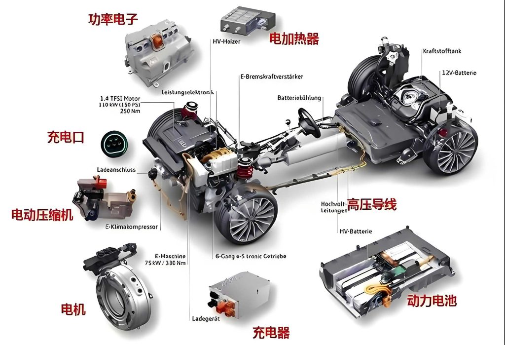
The overall design of the test system is centered on creating a flexible and scalable platform that can accommodate various testing scenarios for battery electric vehicle drive motors. The system architecture comprises three main layers: the upper-level monitoring platform, the middle-level controller, and the lower-level sensor and actuator network. The upper level utilizes LabVIEW software running on a PC to serve as the human-machine interface (HMI), where operators can configure test parameters, monitor real-time data, and analyze results. This layer communicates with the middle level via Ethernet, ensuring fast and reliable data exchange. For remote monitoring, 4G communication technology is employed, enabling off-site access to test data—a feature particularly useful for distributed manufacturing facilities in the battery electric vehicle supply chain.
The middle level is built around a Siemens S7-1200 PLC (model 1214C), which acts as the central controller. This PLC was chosen for its robust performance, ample memory, and integrated digital I/O capabilities, making it suitable for handling multiple sensor inputs and control outputs simultaneously. It receives data from various sensors, processes it, and sends control signals to the motor controller and inverter that drive the test motor. Additionally, the PLC can adjust torque and speed based on commands from the upper level, allowing for precise simulation of different operating conditions. The lower level consists of sensors that measure critical parameters: electrical quantities (voltage and current), torque, speed, and temperature. These sensors feed data into the PLC, forming a closed-loop control system that ensures accurate and repeatable tests. The integration of these layers enables comprehensive evaluation of battery electric vehicle drive motors, from basic functionality to complex performance metrics.
To illustrate the hardware components, Table 1 summarizes the key sensors used in the system, along with their specifications and roles. This selection was guided by the need for high accuracy, reliability, and compatibility with battery electric vehicle applications.
| Sensor Type | Model | Measurement Range | Key Features | Application in Battery Electric Vehicle Testing |
|---|---|---|---|---|
| Temperature Sensor | Pt100 | -100°C to 400°C | High precision, durable probe for internal motor placement | Monitors motor winding and magnet temperature to prevent overheating |
| Torque-Speed Sensor | ZJ-A | Customizable based on motor rating | Stable performance, low interference, compact size | Measures output torque and speed for efficiency calculation |
| Electrical Parameter Sensor | ACS756 Hall Effect | Up to 50 A and 600 V | Measures arbitrary waveforms, high reliability | Captures voltage and current for power and loss analysis |
The software design is a crucial aspect of the system, as it governs data acquisition, processing, and visualization. I developed the upper-level platform using LabVIEW, a graphical programming environment well-suited for virtual instrumentation. The software structure is modular, consisting of initialization, parameter setting, test execution, data logging, and analysis modules. Upon startup, the system initializes all hardware components and prompts the user to set motor parameters, such as rated voltage, current, and speed. The test menu offers options for various experiments: no-load test, load test, variable operating condition test, and acceleration-deceleration test. During testing, real-time data is displayed on the front panel using graphs and numerical indicators, and all data is simultaneously saved to a Microsoft Access database via ODBC connectivity. This database integration allows for easy retrieval, querying, and printing of historical data, addressing common issues of data disorganization in traditional test systems.
One of the innovative features of this system is the implementation of a neural network-based prediction model for motor temperature. In battery electric vehicles, drive motors are subject to losses—such as copper losses and iron losses—that generate heat during operation. Excessive temperature can cause permanent demagnetization of magnets or insulation failure, leading to reduced motor life or safety hazards. To mitigate this, I incorporated a backpropagation (BP) neural network algorithm, which excels at modeling nonlinear relationships. The model takes input parameters like torque, speed, current motor temperature, and ambient temperature, and outputs a predicted temperature. The BP network consists of an input layer, hidden layers, and an output layer, with forward and backward propagation processes to minimize prediction error. The mathematical representation of the network can be expressed as follows:
Let the input vector be $\mathbf{x} = [x_1, x_2, \ldots, x_n]^T$, where $x_i$ represents parameters like torque or speed. The output $y$ (predicted temperature) is computed through weighted sums and activation functions. For a single hidden layer with $m$ neurons, the output of the $j$-th hidden neuron is:
$$ h_j = f\left(\sum_{i=1}^{n} w_{ij}^{(1)} x_i + b_j^{(1)}\right) $$
where $w_{ij}^{(1)}$ are weights from input to hidden layer, $b_j^{(1)}$ are biases, and $f$ is the activation function (e.g., sigmoid). The final output is:
$$ y = g\left(\sum_{j=1}^{m} w_{j}^{(2)} h_j + b^{(2)}\right) $$
where $g$ is the output activation function. During training, the mean squared error (MSE) between predicted and actual temperatures is minimized using gradient descent:
$$ \text{MSE} = \frac{1}{N} \sum_{k=1}^{N} (y_k – \hat{y}_k)^2 $$
where $N$ is the number of samples, $y_k$ is the predicted value, and $\hat{y}_k$ is the actual temperature. This model enables proactive temperature monitoring, allowing for early warnings before critical levels are reached in battery electric vehicle drive motors.
To validate the system’s performance, I conducted a series of tests focusing on speed control accuracy and temperature prediction. For speed control, the test motor was operated at various setpoints from 0 rpm to 2800 rpm, with increments of 400 rpm. At each point, the actual speed was recorded, and the error was calculated. The results, shown in Table 2, demonstrate that the system maintains speed errors within ±2 rpm, which complies with the GB/T 18488-2024 standard for battery electric vehicle drive motor systems, specifying control accuracy within -50 to 50 rpm for speeds below 10,000 rpm.
| Set Speed (rpm) | Actual Speed (rpm) | Error (rpm) | Compliance with Standard |
|---|---|---|---|
| 0 | 0.1 | +0.1 | Yes |
| 400 | 399.8 | -0.2 | Yes |
| 800 | 801.5 | +1.5 | Yes |
| 1200 | 1199.3 | -0.7 | Yes |
| 1600 | 1601.9 | +1.9 | Yes |
| 2000 | 1999.6 | -0.4 | Yes |
| 2400 | 2400.2 | +0.2 | Yes |
| 2800 | 2799.7 | -0.3 | Yes |
In addition to speed control, the system’s ability to predict motor temperature was evaluated. Using historical data from battery electric vehicle drive motor tests, the BP neural network was trained and then applied to new operating conditions. The predicted temperatures were compared with actual measurements, as illustrated in Figure 4 (though not shown here, the trend indicates close alignment). To quantify the correlation, the coefficient of determination (R²) was calculated, yielding a value of 0.93029, which indicates a strong linear relationship and validates the model’s accuracy. This high R² value confirms that the neural network effectively captures the thermal dynamics of battery electric vehicle drive motors, making it a reliable tool for predictive maintenance.
The efficiency of the drive motor is another critical parameter in battery electric vehicles, as it directly impacts energy consumption and range. The test system calculates efficiency based on input and output power measurements. Input power $P_{\text{in}}$ is derived from voltage and current readings:
$$ P_{\text{in}} = \sqrt{3} \times V_{\text{line}} \times I_{\text{line}} \times \cos(\phi) $$
where $V_{\text{line}}$ is the line voltage, $I_{\text{line}}$ is the line current, and $\cos(\phi)$ is the power factor. Output power $P_{\text{out}}$ is computed from torque $T$ and speed $n$:
$$ P_{\text{out}} = \frac{2\pi \times T \times n}{60} $$
Thus, motor efficiency $\eta$ is given by:
$$ \eta = \frac{P_{\text{out}}}{P_{\text{in}}} \times 100\% $$
During tests, these calculations are performed in real-time within LabVIEW, allowing for immediate assessment of motor performance. For instance, in a rated load test where the motor operates at 2935 rpm and 35.8 Nm, the system continuously monitors and logs these values, displaying them on the front panel alongside efficiency trends. This capability is essential for optimizing battery electric vehicle drive systems for maximum energy utilization.
Beyond basic testing, the system supports advanced analyses such as loss segregation and thermal mapping. Copper losses $P_{\text{cu}}$ can be estimated from stator resistance $R_s$ and current $I$:
$$ P_{\text{cu}} = 3 \times I^2 \times R_s $$
Similarly, iron losses $P_{\text{fe}}$ are modeled as a function of frequency and flux density, though detailed formulas depend on motor design. By integrating these loss models, the system provides a comprehensive profile of motor behavior under various loads, aiding in the design of more efficient battery electric vehicle drive motors.
The scalability of the test system is another advantage. As the battery electric vehicle industry evolves, motors may require testing under extreme conditions or with new materials. The modular architecture of this system allows for easy upgrades, such as adding more sensors or integrating machine learning algorithms for anomaly detection. For example, future iterations could incorporate reinforcement learning to optimize test sequences autonomously, reducing human intervention and further enhancing throughput.
In conclusion, the design of this battery electric vehicle drive motor test system represents a significant step forward in automotive testing technology. By combining S7-1200 PLC control with LabVIEW-based virtual instrumentation, the system achieves high precision, reliability, and user-friendliness. The inclusion of neural network predictions for temperature rise adds a proactive dimension to motor health monitoring, potentially preventing failures and extending service life. Experimental results confirm that the system meets international standards for speed control and offers accurate data analysis capabilities. As the demand for battery electric vehicles continues to soar, such test systems will play a crucial role in ensuring product quality, safety, and performance. Moving forward, I plan to enhance the system with cloud connectivity for big data analytics, enabling deeper insights into motor behavior across fleets of battery electric vehicles. This ongoing development aligns with the global push toward sustainable transportation, ultimately contributing to a greener future.