
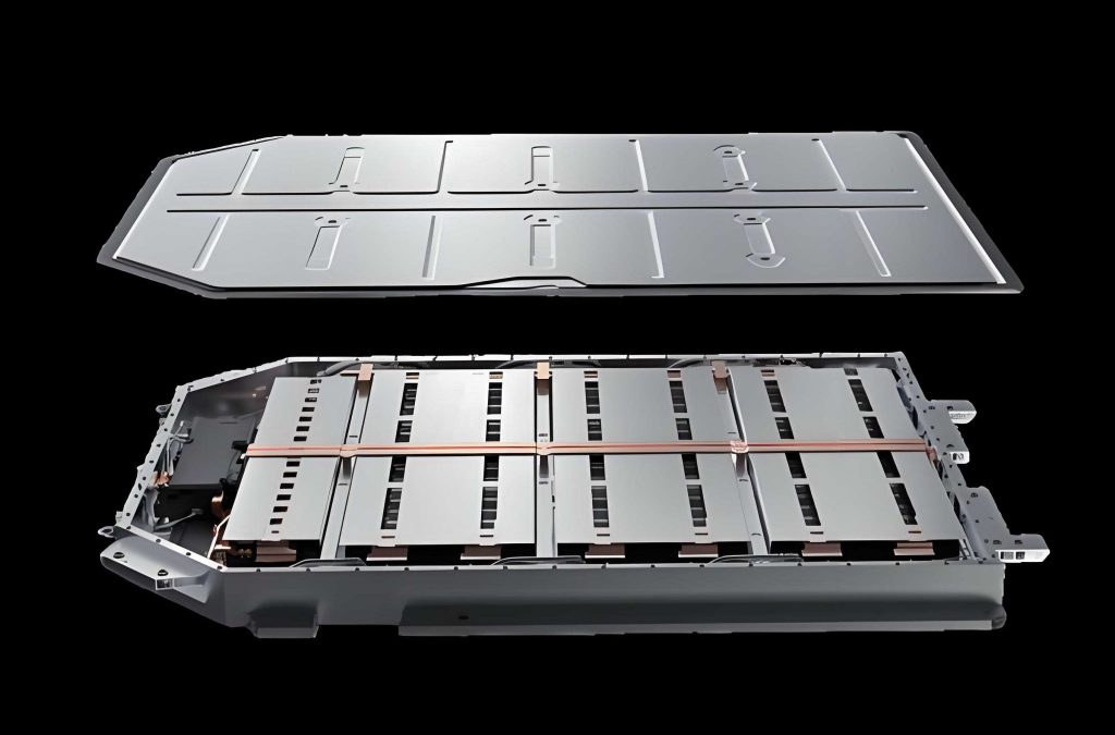
In my work with electric vehicle battery pack service, repair, and production quality control, I have come to treat housing airtightness as one of the most important physical barriers in the entire high-voltage system. The electric vehicle battery pack is not merely an energy storage box. It is a pressure-bearing, water-resistant, dust-resistant, electrically insulated, thermally managed assembly that must survive years of vibration, thermal cycling, road splash, humidity, and occasional immersion. When I inspect an electric vehicle battery pack, I am not just looking for a leak. I am looking for evidence that the enclosure, seals, connectors, vents, cooling interfaces, and service covers still form a coherent sealed system.
My earlier work on coolant-channel airtightness taught me that different sealed volumes inside an electric vehicle battery pack require very different test pressures and acceptance limits. The housing itself is a low-pressure, large-volume barrier. The coolant circuit is a high-pressure, small-volume barrier. The refrigerant circuit, when present, is another high-pressure barrier with different chemistry, oil compatibility, and leak-detection physics. A complete electric vehicle battery pack airtightness strategy must respect these differences rather than applying one universal leak test to every cavity.
This article is my practical and technical synthesis of electric vehicle battery pack housing airtightness inspection. I focus on the differential-pressure method because it dominates production lines and service workshops. I also discuss standards, instrumentation, process design, fault localization, data traceability, and the cross-application of sealing knowledge between air, coolant, and refrigerant systems. My aim is to show how a quantitative pressure-decay test can become a reliable, repeatable, and diagnostic tool for the electric vehicle battery pack.
1. Why Airtightness Matters in an Electric Vehicle Battery Pack
A sealed electric vehicle battery pack protects its internal cells, modules, busbars, sensing harnesses, battery management system, and high-voltage connectors from external media. The most obvious threat is water. Road splash, rain, steam cleaning, flooded roads, and short-term immersion can all drive liquid water toward the enclosure. If water enters the electric vehicle battery pack, it can bridge insulation paths, corrode terminals, accelerate electrochemical degradation, and create partial discharge or arc tracks. In severe cases, water intrusion can contribute to thermal runaway.
Dust and particulate matter are also threats. Although dust is less immediately destructive than water, conductive dust can reduce insulation resistance. Fine metallic particles from brakes or road wear can settle on surfaces and create leakage paths. In a high-voltage electric vehicle battery pack, even a small conductive path can lead to isolation faults and diagnostic trouble codes.
Humidity is a slower but equally important threat. A sealed electric vehicle battery pack that is not truly sealed can breathe moist air as temperature changes. Over many thermal cycles, water vapor can migrate inward, condense on cold surfaces, and accumulate in low points. This is why airtightness is not only about visible water entry. It is also about controlling the long-term moisture balance inside the electric vehicle battery pack.
The safety consequences are serious. A leak in the housing can allow water to reach high-voltage components. That can cause short circuits, insulation failure, overcurrent, arcing, and in extreme cases fire. A leak in a cooling plate or coolant hose inside the electric vehicle battery pack can allow coolant to contact cells or electronics. A leak in a vent or service cover can allow moisture ingress during a car wash or a deep-water crossing. Each of these failure modes has a different root cause, but all of them can be detected or prevented through an effective electric vehicle battery pack airtightness program.
I have seen how small manufacturing defects can become large field problems. An uneven sealing surface around a pressure-relief vent, a pinched O-ring, a weld pore, a scratched mating flange, or an under-torqued fastener can all produce a leak that is invisible at the time of assembly. A quantitative airtightness check converts that hidden defect into a measurable pressure decay. That is why I regard airtightness inspection as the first external defense of the electric vehicle battery pack and as a critical final gate before the pack is installed in the vehicle.
2. Basic Concepts and Physical Model
Airtightness, also called leak testing, is the evaluation of a sealed enclosure’s ability to resist the transfer of a gas or liquid through its boundary. In the context of an electric vehicle battery pack, the boundary includes the housing walls, welded seams, bolted flanges, gaskets, seals, connectors, vents, service disconnects, cooling ports, and any other penetration. Airtightness is usually expressed through a leak rate, a pressure decay, or a classification such as an IP protection level.
An IP code describes the degree of protection against solid objects and water. For an electric vehicle battery pack, IP67 and IP68 are common targets. IP67 means dust-tight and protected against temporary immersion in water under defined conditions. IP68 means dust-tight and protected against continuous immersion under conditions agreed between manufacturer and user. IP69K adds protection against high-pressure, high-temperature water jets. These ratings are not interchangeable. A pack that passes IP67 may not pass IP68, and a pack that passes IP68 may not pass IP69K.
From a physics perspective, a leak is a flow path between a region of higher pressure and a region of lower pressure. In a positive-pressure airtightness test, I fill the electric vehicle battery pack housing with clean, dry air or nitrogen. If the housing is sealed, the internal pressure remains nearly constant after stabilization. If there is a leak, the internal pressure decreases with time. The rate of decrease depends on the leak geometry, the pressure difference, the gas properties, the temperature, and the volume of the sealed cavity.
The ideal gas law provides the starting point for my mental model:
$$P V = n R T$$
Here, P is absolute pressure, V is the sealed volume, n is the amount of gas in moles, R is the universal gas constant, and T is absolute temperature. For an electric vehicle battery pack housing, V is relatively large. That large volume makes the pressure decay slower for a given leak rate, which is helpful for stability but also means that temperature changes can create large apparent pressure changes. I must always separate true leakage from thermal effects.
If the temperature and volume are constant, then the change in pressure over time is proportional to the change in the amount of gas:
$$n = \frac{P V}{R T}$$
The mass flow rate through the leak can be written as:
$$Q_m = -\frac{dm}{dt} = -\frac{d}{dt}\left(\frac{P V}{R T}\right)$$
For constant V and T, this becomes:
$$Q_m = -\frac{V}{R T}\frac{dP}{dt}$$
In service and production, I rarely work directly in moles. I prefer volumetric leak rate at standard conditions because it is easier to compare with manufacturer limits and historical data. If the measured pressure decay is ΔP over a time interval Δt, then an approximate standard volumetric leak rate is:
$$Q_{std} = \frac{V}{P_{std}}\frac{\Delta P}{\Delta t}$$
Here, P_std is the standard absolute pressure used for the leak-rate definition. The units may be cm³/min, mL/min, or Pa/s depending on the instrument and the specification. The key idea is that the leak rate is proportional to the pressure decay and the sealed volume, and inversely proportional to the test time.
3. Differential-Pressure Method in Practice
The differential-pressure method, also called the direct pressure-decay method, is the most practical quantitative method for the electric vehicle battery pack housing. In my experience, it offers a good balance between sensitivity, speed, cost, and robustness in a workshop or production environment.
The method has several stages. First, I seal all openings of the electric vehicle battery pack housing with appropriate fixtures. These openings may include the service disconnect port, vent ports, coolant inlet and outlet, high-voltage connector openings, and any temporary shipping covers. Second, I charge the housing with clean, dry air or nitrogen to a specified test pressure. Third, I close the supply valve and allow the pressure to stabilize. Fourth, I measure the pressure change over a defined test interval. Fifth, I compare the result with the acceptance threshold and generate a pass or fail decision.
The differential-pressure method can be configured in two ways. In a simple gauge-pressure decay test, I measure absolute or gauge pressure inside the electric vehicle battery pack. In a true differential configuration, I compare the pressure inside the test volume with a reference volume that is sealed and temperature-matched. The differential pressure is:
$$\Delta P_{diff} = P_{test} – P_{ref}$$
If both volumes experience the same temperature change, the common-mode thermal effect cancels to a large degree. This is a major advantage for the electric vehicle battery pack because its large plastic or thin-metal housing can change shape and temperature during a test.
The differential-pressure method is not without limitations. A very large leak may prevent the system from reaching the set pressure, which is an immediate fail. A very small leak may be hidden by noise, temperature drift, or elastic deformation of the housing. I therefore pay close attention to stabilization time, test time, pressure sensor resolution, and fixture rigidity.
I also consider the flow regime through the leak. For a small leak, the flow may be laminar and proportional to the pressure difference. For a larger leak or a short channel, the flow may be turbulent or choked. The following relationships help me understand the behavior:
$$Q = C_d A \sqrt{\frac{2 \Delta P}{\rho}}$$
This is a simplified turbulent orifice equation. Here, Q is volumetric flow, C_d is the discharge coefficient, A is the effective leak area, ΔP is the pressure difference, and ρ is the gas density. For laminar flow through a narrow channel, the relationship is different:
$$Q = \frac{\pi d^4 \Delta P}{128 \mu L}$$
Here, d is the effective channel diameter, μ is the dynamic viscosity, and L is the channel length. These formulas remind me that leak rate is not a single fixed property. It depends on the flow regime, the gas, the pressure, and the geometry. That is why the electric vehicle battery pack must be tested under controlled conditions.
4. Temperature, Volume, and Deformation Compensation
Temperature compensation is essential for reliable electric vehicle battery pack airtightness testing. A large sealed volume will show a pressure change when the gas temperature changes, even if there is no leak. This is not a defect. It is physics. If I ignore it, I will create false failures and unnecessary rework.
The uncorrected pressure change can be approximated by:
$$\Delta P_{thermal} \approx P_0 \frac{\Delta T}{T_0}$$
Here, P_0 is the initial absolute pressure, T_0 is the initial absolute temperature, and ΔT is the temperature change during the test. For example, if the initial absolute pressure is 250 kPa and the temperature rises by 1 K from 293 K, the thermal pressure change is approximately:
$$\Delta P_{thermal} \approx 250000 \times \frac{1}{293} \approx 853 \text{ Pa}$$
That value can be much larger than the true leak signal I am trying to detect. This is why I insist on temperature stabilization and, when possible, differential measurement against a reference volume.
A practical corrected leak rate can be expressed as:
$$Q_{corr} = Q_{meas} \frac{T_{ref}}{T_{meas}}$$
Alternatively, the corrected pressure decay is:
$$\Delta P_{corr} = \Delta P_{meas} \frac{T_{ref}}{T_{meas}}$$
Here, T_ref is the reference absolute temperature, and T_meas is the measured absolute temperature. The exact compensation method depends on the instrument and the manufacturer’s algorithm. My responsibility is to verify that the instrument is using the correct sensor inputs and that the temperature sensors are placed in representative locations.
Volume change is another factor. An electric vehicle battery pack housing made of plastic or thin aluminum can expand or contract under test pressure. This elastic deformation changes the internal volume and therefore changes the pressure. The effect can be approximated as:
$$\Delta P_{deform} \approx -P_0 \frac{\Delta V}{V_0}$$
If the housing expands, the internal volume increases, and the pressure drops. That pressure drop can look like a leak. I have observed visible bulging on some polymer housings when the test pressure exceeded the manufacturer’s recommended value. This is why I never increase the test pressure just to make a leak easier to find. Over-pressurization can damage the electric vehicle battery pack, deform seals, or create false failures.
To control these effects, I use the following practices:
- Allow the electric vehicle battery pack to soak at room temperature before testing.
- Use a regulated, dry, clean air supply with stable temperature.
- Use a reference volume with similar thermal mass when differential testing is available.
- Keep the test pressure within the manufacturer’s specification.
- Allow sufficient stabilization time before the measurement interval.
- Record ambient temperature, gas temperature, and test pressure for traceability.
5. Standards and Acceptance Criteria
Standards provide the common language for electric vehicle battery pack airtightness. The most relevant safety standard for traction batteries requires waterproof sealing tests such as IPX7. However, a full immersion test is destructive in the sense that it exposes the pack to water and is not suitable for every unit on a production line. For this reason, industry uses non-destructive equivalent methods, including pressure-decay and differential-pressure tests, to infer the IP performance of the electric vehicle battery pack.
Standardization at the regional and industry level may define test pressure, stabilization time, measurement time, and leak-rate limits. I always verify the latest applicable standard and the manufacturer’s internal specification before setting up a test. A test that is too loose will miss real leaks. A test that is too tight will reject good packs and increase cost.
| IP Level | Key Test Condition | Protection Meaning | Typical Use in Electric Vehicle Battery Pack |
|---|---|---|---|
| IPX7 | Immersion in 1 m water for 30 minutes | Temporary immersion protection | Common baseline for battery pack water resistance |
| IPX8 | Continuous immersion, depth and time agreed by supplier and user | Higher water resistance | Used when the electric vehicle battery pack must survive longer or deeper immersion |
| IP67 | Dust-tight plus temporary immersion | Combined dust and water protection | Widely specified for road electric vehicle battery pack enclosures |
| IP68 | Dust-tight plus continuous immersion | High combined protection | Used for premium or severe-duty electric vehicle battery pack designs |
| IP69K | High-pressure, high-temperature water jets | Extreme washdown protection | Sometimes combined with IP68 for commercial or off-road electric vehicle battery pack applications |
Acceptance criteria should be based on the sealed volume, the test pressure, the test time, and the expected leak mechanism. A large electric vehicle battery pack housing may have a leak limit expressed in cm³/min or Pa/s. A small coolant channel may have a much tighter limit at a much higher pressure. I never use the same limit for both.
| Test Target | Typical Pressure Range | Typical Test Time | Typical Leak Metric | Primary Risk |
|---|---|---|---|---|
| Electric vehicle battery pack housing | Low positive pressure | 30 s to 120 s | cm³/min or Pa | Water and dust ingress |
| Coolant channel inside pack | High positive pressure | 30 s to 60 s | cm³/min or Pa | Coolant leakage and short circuit |
| Refrigerant circuit | High pressure, sometimes negative | Variable | g/year or pressure decay | Refrigerant loss and cooling failure |
| Service cover seal | Low positive pressure | 20 s to 60 s | Pa or cm³/min | Local water entry |
| Vent or pressure equalization device | Low positive and negative pressure | 10 s to 30 s | Pa or flow rate | Moisture breathing and seal inversion |
I also consider the difference between a leak specification and a diagnostic threshold. The specification is the maximum leak rate allowed for a new or repaired electric vehicle battery pack. The diagnostic threshold may be tighter or looser depending on the purpose. For warranty inspection, I may use a tighter threshold to detect early degradation. For a quick field check, I may use a slightly looser threshold to avoid false alarms, but I never ignore a trend of increasing leak rate.
6. Selecting the Right Test Pressure
Test pressure selection is a compromise between sensitivity and safety. Higher pressure increases the flow through a leak and therefore makes the leak easier to detect. However, higher pressure also increases mechanical stress on the electric vehicle battery pack housing, seals, welds, and internal components. Many housings use polymer materials, thin aluminum, or composite structures that are not designed for high internal pressure.
In my practice, the housing test pressure is typically a small fraction of the coolant-channel test pressure. The exact value depends on the manufacturer’s specification. I have seen cases where a modest increase above the recommended pressure caused visible expansion of a plastic electric vehicle battery pack housing. That deformation can damage the pack or create a false leak signal.
The following approximate relationship helps me compare leak sensitivity at different pressures:
$$Q \propto \Delta P^{m}$$
For laminar flow, m is approximately 1. For turbulent flow, m is approximately 0.5. For choked flow, the relationship becomes more complex. In general, increasing ΔP increases Q, but the benefit diminishes at higher pressures and the mechanical risk increases.
I use the following guidelines when selecting a test pressure for an electric vehicle battery pack housing:
- Never exceed the manufacturer’s maximum test pressure.
- Use the lowest pressure that provides a reliable signal above noise.
- Verify that the pressure sensor range is appropriate for the test pressure.
- Confirm that fixtures and seals are rated for the test pressure.
- Check for visible deformation during the first test of a new pack type.
- Document the pressure setpoint and actual pressure for every test.
7. Instrumentation and Calibration
The instrument is the heart of an electric vehicle battery pack airtightness test. A good instrument must provide stable pressure regulation, high-resolution pressure measurement, repeatable valve timing, temperature compensation, and clear pass/fail output. It must also protect the electric vehicle battery pack from over-pressurization and contamination.
Compressed air is often used because it is available in most workshops. However, shop air can contain oil, water, and particles. I always use a filtration train that includes a coarse separator, a fine coalescing filter, and a precision regulator. For sensitive tests, I prefer dry nitrogen because it is inert, dry, and clean. The gas supply must be stable in temperature and pressure.
There are single-function and dual-function instruments. A single-function instrument is dedicated to either housing testing or coolant-channel testing. A dual-function instrument can perform both, but the pressure ranges and sensor resolutions are different. In a busy electric vehicle battery pack repair line, a dual-function instrument can serve as a backup and reduce downtime. However, I verify that the instrument uses the correct internal sensor and menu for each test. Connecting a housing test to a high-pressure coolant port, or vice versa, can damage the electric vehicle battery pack or the instrument.
Calibration is non-negotiable. I check the instrument against a known reference at the beginning of each shift or at the frequency recommended by the quality system. I also verify leak-tightness of the test fixtures themselves. A leaking fixture can make a good electric vehicle battery pack appear defective. The fixture leak rate should be at least an order of magnitude lower than the acceptance limit.
| Instrument Feature | Why It Matters for Electric Vehicle Battery Pack Testing | Practical Check |
|---|---|---|
| Pressure resolution | Detects small pressure decay in a large housing volume | Compare displayed resolution with calculated minimum detectable leak |
| Temperature compensation | Reduces false failures from thermal drift | Verify temperature sensor placement and response |
| Differential channel | Cancels common-mode thermal and supply pressure effects | Test with a known sealed reference volume |
| Programmable test sequence | Ensures repeatable fill, stabilize, measure, and exhaust times | Audit sequence against work instruction |
| Over-pressure protection | Prevents damage to thin-walled electric vehicle battery pack housings | Test pressure limit and relief valve function |
| Data logging | Supports traceability, trend analysis, and recall containment | Confirm time stamp, serial number, and result storage |
| Barcode or QR input | Links test result to the specific electric vehicle battery pack | Scan a sample and verify record matching |
8. Standardized Test Workflow
A standardized workflow is essential for consistent electric vehicle battery pack airtightness results. I structure the process into preparation, connection, charging, stabilization, measurement, evaluation, and documentation. Each step has a purpose, and skipping a step can compromise the result.
| Step | Action | Key Control | Common Error |
|---|---|---|---|
| 1. Preparation | Inspect the electric vehicle battery pack for damage, moisture, and debris | Clean and dry sealing surfaces | Testing a wet or dirty pack |
| 2. Fixture installation | Seal all openings with correct adapters and gaskets | Use the correct port map | Missing an open port |
| 3. Leak check of fixtures | Verify test setup tightness | Use a known-good blank or reference volume | Fixture leak mistaken for pack leak |
| 4. Charging | Fill the housing to the specified test pressure | Use clean, dry gas | Over-pressurization |
| 5. Stabilization | Wait for temperature and pressure equilibrium | Follow specified stabilization time | Starting measurement too early |
| 6. Measurement | Record pressure decay over the specified interval | Maintain stable ambient conditions | Temperature drift during test |
| 7. Evaluation | Compare result with the acceptance limit | Apply correct units and compensation | Using the wrong leak limit |
| 8. Documentation | Store result with pack identifier, operator, and time | Traceability and audit trail | Incomplete record |
| 9. Exhaust and disconnect | Release pressure safely and remove fixtures | Prevent sudden pressure release | Damage to seals or housing |
During preparation, I check that the electric vehicle battery pack is at a stable temperature. If it has just been washed, driven, or charged, I allow it to cool or warm to ambient. I also check that all ports are identified correctly. A common mistake is to leave a shipping plug in place or to seal the wrong vent. That can create a false pass or a false fail.
During charging, I monitor the pressure rise. If the pressure does not reach the setpoint within the expected time, there may be a large leak or a fixture problem. If the pressure rises too quickly, the regulator may be set incorrectly. During stabilization, I watch for pressure drift. A slowly rising pressure can indicate outgassing or thermal expansion. A slowly falling pressure can indicate a leak or cooling.
During measurement, I ensure that no one touches the electric vehicle battery pack, the hoses, or the fixtures. Mechanical disturbance can create pressure spikes. I also avoid direct sunlight, strong airflow, or localized heating. These environmental factors can change the temperature of the housing and distort the result.
9. Leak Rate Calculation and Reporting
The raw output of a pressure-decay test is a pressure difference over time. To make the result useful, I convert it to a leak rate and compare it with the specification. The basic conversion is:
$$Q = \frac{V \Delta P}{P_{std} \Delta t}$$
For practical reporting, I often convert to cm³/min:
$$Q_{cm^3/min} = \frac{V \Delta P}{P_{std} \Delta t} \times 60$$
Here, V is the sealed volume, ΔP is the pressure decay, P_std is the standard pressure, and Δt is the measurement time. The units must be consistent. If V is in cm³, ΔP in Pa, P_std in Pa, and Δt in seconds, then the result is in cm³/s. Multiplying by 60 gives cm³/min.
I also record the minimum detectable leak rate. This helps me judge whether a passing result is meaningful. The minimum detectable pressure change is limited by sensor resolution and noise:
$$\Delta P_{min} = \frac{Q_{min} P_{std} \Delta t}{V}$$
If the calculated ΔP_min is larger than the acceptance limit, the test is not capable of proving compliance. In that case, I must increase test time, reduce volume if possible, improve temperature stability, or use a more sensitive instrument.
For differential-pressure instruments, the reported value may already be a leak rate. I still verify the internal calculation by comparing with a calibrated leak standard. A calibrated leak standard is a small, stable orifice or capillary that produces a known leak rate under specified conditions. It is one of the best ways to validate the entire test system, including fixtures, hoses, and instrument.
| Parameter | Symbol | Typical Unit | Effect on Leak Rate |
|---|---|---|---|
| Sealed volume | V | cm³ or L | Larger volume gives smaller pressure decay for the same leak |
| Pressure decay | ΔP | Pa | Directly proportional to leak rate |
| Measurement time | Δt | s | Longer time improves resolution but slows the process |
| Test pressure | P_test | kPa or Pa | Higher pressure increases flow through the leak |
| Absolute temperature | T | K | Temperature change creates false pressure decay |
| Standard pressure | P_std | Pa | Normalizes leak rate to reference conditions |
10. Leak Localization and Root Cause Analysis
A failed airtightness test tells me that the electric vehicle battery pack has a leak, but it does not tell me where the leak is. To repair the pack efficiently, I need localization. I use a combination of methods depending on the leak size, accessibility, and risk of contamination.
The soap bubble method is simple and effective for relatively large leaks at low pressure. I apply a soap solution to suspect areas and watch for bubbles. It is useful for welds, flanges, hose connections, and threaded ports. However, it can leave residue, so I must clean the area afterward. It is not sensitive enough for very small leaks.
Ultrasonic leak detection is useful for pressurized gas leaks that produce turbulent flow. The ultrasonic sensor can detect high-frequency noise from the leak and help me locate it from a distance. This method works well when the electric vehicle battery pack is partially assembled and the leak is accessible.
Tracer gas methods, such as helium leak detection, offer high sensitivity. Helium is inert, has small molecules, and can be detected at very low concentrations. I use helium when the acceptance limit is very tight or when the leak is too small for pressure decay to localize. The electric vehicle battery pack is evacuated or pressurized with helium, and a mass spectrometer probe is moved around suspect areas.
Pressure decay mapping is another approach. I divide the electric vehicle battery pack into zones and test each zone separately by sealing internal passages. This can isolate a leak to a specific module, coolant plate, or connector area. It requires more fixtures and time, but it can be very effective for complex packs.
| Localization Method | Sensitivity | Best Use | Limitations |
|---|---|---|---|
| Soap bubble | Low to medium | Large leaks, accessible joints | Residue, operator dependent |
| Ultrasonic | Medium | Pressurized gas leaks, noisy environments | Needs turbulent flow, background noise |
| Helium tracer gas | High | Small leaks, tight specifications | Cost, helium supply, calibration |
| Pressure decay zoning | Medium to high | Complex electric vehicle battery pack assemblies | Fixtures, time, internal access |
| Dye penetration | Medium | Coolant channels and accessible surfaces | Cleanup, not for all materials |
| Thermal imaging | Low to medium | Coolant leaks with temperature difference | Requires temperature contrast |
Once I find the leak, I perform root cause analysis. Common causes include weld porosity, incomplete weld penetration, gasket compression set, O-ring damage, incorrect torque, scratched sealing surfaces, foreign object debris, thread sealant failure, and housing deformation. The repair must address the root cause, not just the symptom. For example, if a flange bolt is loose, I check the torque specification and the bolt sequence. If a seal is pinched, I inspect the mating surface for burrs and sharp edges.
11. Interaction Between Housing, Coolant, and Refrigerant Sealing
An electric vehicle battery pack often contains multiple sealed systems. The housing is a low-pressure air barrier. The coolant loop is a high-pressure liquid barrier. The refrigerant loop, if present, is a high-pressure phase-change barrier. Each system has different leak mechanisms, test pressures, and acceptance criteria. However, they interact inside the same package.
If a coolant line leaks inside the electric vehicle battery pack housing, the liquid can accumulate at the bottom of the enclosure. In a housing airtightness test, this liquid may block the leak path or change the internal volume. If the coolant line leaks into the housing, the housing pressure test may show unusual behavior. I have explored the idea of using the housing test as an indirect coolant leak indicator. If the coolant loop is connected to the housing through a leak, the high-pressure coolant side may pressurize the housing during the coolant test. Conversely, during a housing test, the pressure may migrate into the coolant loop if the coolant cap is open.
I have also considered using the housing airtightness test to infer refrigerant leakage. Refrigerant leaks are usually detected with electronic sniffers, pressure decay, or vacuum hold tests. But if a refrigerant line runs inside the electric vehicle battery pack, a leak could contaminate the housing atmosphere. A high-precision humidity or chemical sensor in the test exhaust could potentially detect refrigerant or coolant vapor. This is an emerging area, and I treat it as a diagnostic supplement rather than a replacement for dedicated leak detection.
| Sealed System | Typical Pressure | Test Gas or Fluid | Leak Concern | Detection Method |
|---|---|---|---|---|
| Electric vehicle battery pack housing | Low positive pressure | Air or nitrogen | Water, dust, humidity ingress | Pressure decay, differential pressure |
| Coolant loop | High positive pressure | Air, nitrogen, or coolant | Coolant loss, short circuit, corrosion | Pressure decay, dye, vacuum |
| Refrigerant loop | High positive or negative pressure | Refrigerant, nitrogen, helium | Refrigerant loss, cooling loss, oil loss | Electronic sniffer, vacuum decay, helium |
| Vent device | Low positive and negative pressure | Air | Moisture breathing, seal inversion | Flow test, pressure hold |
| Service cover | Low positive pressure | Air | Local water entry | Pressure decay, soap bubble |
From a sealing perspective, I try to standardize connection ports and adapters. If a coolant test port can be accidentally connected to a housing test port, the electric vehicle battery pack may be over-pressurized. I use different connector sizes, color coding, and interlocks to prevent cross-connection. I also verify that the instrument menu and the physical port match the test being performed.
12. Field and Service Applications
In routine maintenance, I use electric vehicle battery pack airtightness inspection as a preventive check. The vehicle may not show any fault codes, but a small leak can be developing. A pressure-decay test can reveal a trend before water ingress causes a failure. I pay special attention to vehicles that operate in wet climates, near coastlines, or on unpaved roads. These environments increase the risk of corrosion and seal degradation.
In battery overhaul, airtightness is a final quality gate. After replacing modules, coolant plates, seals, or connectors, I test the electric vehicle battery pack before it is returned to service. The test confirms that the repair did not introduce a leak and that the original sealing performance has been restored. I also test after any structural repair, such as welding or straightening, because heat and mechanical stress can damage seals and coatings.
During warranty inspection, I compare the current leak rate with the historical baseline. If the leak rate has increased significantly, I investigate even if the absolute value is still within specification. A rising trend is an early warning. I may perform a more sensitive test, inspect suspect areas, or recommend replacement of seals and vent devices.
For vehicles that have been flooded or submerged, I perform an airtightness test as part of the damage assessment. However, I first ensure that the electric vehicle battery pack is dry and safe to handle. Water inside the pack can create dangerous conditions. I follow high-voltage safety procedures and use appropriate personal protective equipment.
| Application Scenario | Purpose | Test Frequency | Key Decision |
|---|---|---|---|
| Production line | Verify every new electric vehicle battery pack | 100 percent or sampled | Pass, rework, or scrap |
| Routine maintenance | Detect early seal degradation | Annual or mileage based | Monitor, repair, or replace |
| Battery overhaul | Validate repair quality | After every major repair | Release or rework |
| Warranty claim | Confirm leak-related failure | As needed | Approve or deny claim |
| Flood damage assessment | Determine water intrusion risk | After immersion event | Repair, replace, or retire |
| End-of-life evaluation | Assess reuse or recycling safety | Before second-life use | Reuse, remanufacture, or recycle |
13. Data Management and Traceability
A single pass or fail result is useful, but a database of results is far more valuable. I link every electric vehicle battery pack airtightness test to a unique identifier, such as a serial number or QR code. The record includes the test pressure, temperature, stabilization time, measurement time, pressure decay, calculated leak rate, instrument identifier, operator, and result. This data supports traceability, trend analysis, and continuous improvement.
With enough data, I can analyze the distribution of leak rates for a given electric vehicle battery pack model. I can set statistical process control limits and detect shifts before failures occur. I can also compare different production batches, suppliers, or repair methods. If a particular seal design or weld process produces higher leak rates, the data will reveal it.
Traceability is also important for safety recalls. If a defect is found in a certain production window, the test records help identify affected electric vehicle battery packs. If a repair procedure is changed, the records show whether the change improved or worsened airtightness. In my view, data management transforms airtightness inspection from a simple quality gate into a learning system.
| Data Field | Example Unit | Purpose |
|---|---|---|
| Pack identifier | Text or QR | Traceability |
| Test date and time | Timestamp | Audit trail |
| Ambient temperature | °C | Thermal compensation |
| Gas temperature | °C | Thermal compensation |
| Test pressure | kPa | Test condition |
| Stabilization time | s | Process control |
| Measurement time | s | Process control |
| Pressure decay | Pa | Raw result |
| Calculated leak rate | cm³/min | Acceptance decision |
| Pass or fail | Boolean | Quality gate |
| Instrument identifier | Text | Calibration traceability |
| Operator identifier | Text | Accountability |
14. Common Pitfalls and Troubleshooting
Even a well-designed electric vehicle battery pack airtightness test can produce misleading results. I have learned to recognize several common pitfalls and to troubleshoot them systematically.
One pitfall is testing a pack that is not thermally stable. If the electric vehicle battery pack was recently charged or exposed to sunlight, the internal air temperature may be different from the housing surface temperature. As the pack cools, the pressure drops, and the instrument may report a leak. I solve this by allowing a soak period and by using temperature-compensated or differential testing.
Another pitfall is a leaking fixture. The hoses, adapters, and seals used to connect the instrument to the electric vehicle battery pack can leak. If the fixture leak rate is significant, every pack will appear to leak. I verify fixtures with a blanking plate or a known-good reference volume. I also inspect hoses for cracks and replace worn O-rings regularly.
A third pitfall is the wrong test pressure. If the pressure is too low, the leak signal may be below the noise floor. If the pressure is too high, the housing may deform or seals may be damaged. I always confirm the specified pressure and never adjust it without engineering approval.
A fourth pitfall is the wrong acceptance limit. Using a coolant-channel limit for the housing, or a housing limit for the coolant channel, can cause false passes or false failures. I keep a clear port map and instrument program for each electric vehicle battery pack model.
A fifth pitfall is ignoring the effect of volume. A large electric vehicle battery pack housing requires a longer test time or a more sensitive sensor to detect the same leak rate as a small housing. If the test is too short, a real leak may be missed.
| Symptom | Possible Cause | Verification | Corrective Action |
|---|---|---|---|
| Pressure does not reach setpoint | Large leak or open port | Check port map and listen for leak | Seal open port or repair leak |
| Pressure drops rapidly | Large leak or fixture leak | Blank off pack and test fixture | Repair fixture or pack |
| Pressure rises slowly | Thermal expansion or outgassing | Record temperature trend | Extend stabilization, reduce test time |
| Pressure falls slowly | Small leak or cooling | Compare with reference volume | Use differential mode, inspect seals |
| Result varies between tests | Temperature drift or unstable supply | Log ambient and gas temperature | Stabilize environment, service regulator |
| All packs fail | Wrong acceptance limit or fixture leak | Test known-good pack | Correct program or repair fixture |
| All packs pass | Test not sensitive enough | Introduce calibrated leak | Increase test time or sensitivity |
15. Safety Precautions During Airtightness Testing
Airtightness testing involves compressed gas and high-voltage hardware. I treat safety as a prerequisite, not an afterthought. Before I connect any fixture to an electric vehicle battery pack, I confirm that the high-voltage system is de-energized and locked out. I follow the manufacturer’s service procedures for isolation and verification. I never assume that a pack is safe because it is not connected to a vehicle.
Compressed gas can store significant energy. I use pressure regulators, relief valves, and rated hoses. I avoid sudden pressure releases that can damage seals or create projectiles. I wear safety glasses and, when appropriate, hearing protection. I ensure that the test area is ventilated, especially when using nitrogen or other gases that can displace oxygen.
If the electric vehicle battery pack has been exposed to water or shows signs of damage, I handle it with extra caution. Water inside the pack can create conductive paths and corrosive conditions. I follow high-voltage safety protocols and use insulated tools. If I suspect internal damage, I do not pressurize the pack until it has been inspected and cleared by a qualified person.
16. Future Directions in Electric Vehicle Battery Pack Airtightness
I expect electric vehicle battery pack airtightness inspection to become more integrated, more automated, and more data-driven. Sensors will become smaller and more accurate. Instruments will combine pressure decay, temperature compensation, humidity measurement, and chemical analysis. Test fixtures will become model-specific and self-identifying. Robots and automated handling systems will perform repetitive tests with high repeatability.
I also expect greater use of digital twins. A digital twin of the electric vehicle battery pack can simulate pressure decay under different leak sizes and temperatures. By comparing measured data with the simulation, I can estimate leak size and location more accurately. Machine learning can analyze historical test data to predict which packs are likely to develop leaks in the field. This supports condition-based maintenance and early intervention.
Another trend is the integration of airtightness testing with other end-of-line tests. Instead of separate stations for leak, insulation, and functional checks, a single test sequence can combine them. The electric vehicle battery pack identifier links all results together. This reduces handling, saves time, and improves traceability.
I also see potential in using the housing airtightness test as a broad health check for the entire electric vehicle battery pack. By monitoring pressure decay, temperature, humidity, and trace gases, I can detect coolant leaks, refrigerant leaks, and moisture ingress. This does not replace dedicated tests, but it can provide an early warning that triggers further investigation.
17. Conclusion
Electric vehicle battery pack housing airtightness inspection is a critical part of safety, reliability, and quality. It protects the high-voltage system from water, dust, and humidity. It supports IP67, IP68, and related protection targets. It provides a quantitative measure of sealing performance that can be tracked over time. It helps diagnose manufacturing defects, repair errors, and field degradation.
In my practice, the differential-pressure method is the workhorse for electric vehicle battery pack housing testing. It is quantitative, repeatable, and compatible with production and service environments. The method depends on careful control of pressure, temperature, volume, and time. It also depends on good fixtures, calibrated instruments, and a standardized workflow. When these elements are in place, the test can detect small leaks that would otherwise go unnoticed.
The interaction between housing, coolant, and refrigerant sealing is an important area for further development. Each system has different physics and different risks. By sharing knowledge across these systems, I can improve detection efficiency and accuracy. A coolant leak inside the electric vehicle battery pack, a refrigerant leak in a chiller circuit, and a housing leak at a vent can all affect the same safety outcome. A coordinated sealing strategy is stronger than isolated tests.
Ultimately, airtightness inspection is not just a pass or fail check. It is a window into the health of the electric vehicle battery pack. The pressure decay curve, the leak rate, the temperature trend, and the historical data all tell a story. When I read that story carefully, I can find defects earlier, repair them more precisely, and prevent failures before they happen. That is how I build confidence in the electric vehicle battery pack and in the safety of the people who depend on it.