
In my assessment, the global transition toward sustainable energy has made the solid state cell one of the most consequential technology platforms of this decade. I have examined the evolving landscape of electric vehicles, large-scale energy storage systems, and advanced portable electronics, and I repeatedly find that the solid state cell is positioned as the logical successor to conventional lithium-ion architectures. Yet I also recognize that the transition from liquid-electrolyte cells to fully solid state cell designs is not a single step but a spectrum. Within that spectrum, the semi-solid-state cell has emerged as a pragmatic, near-term, and commercially meaningful solution. I use the term solid state cell throughout this work to describe cells in which a solid electrolyte phase contributes meaningfully to ion transport, mechanical integrity, or safety, even if a residual liquid phase remains present. My first-person perspective is grounded in materials analysis, electrochemical modeling, and industrial feasibility. I do not treat the semi-solid-state cell as a mere compromise; instead, I view it as a carefully engineered bridge that allows the solid state cell concept to enter mass production while the ultimate all-solid-state cell continues its long maturation.
My central argument is that the semi-solid-state cell delivers a rare combination: it improves safety and energy density beyond conventional liquid cells while preserving enough compatibility with existing manufacturing to avoid prohibitive capital expenditure. In my view, the solid state cell family should be understood as a continuum defined by liquid content, solid electrolyte architecture, interfacial behavior, and manufacturing readiness. The semi-solid-state cell occupies the middle of that continuum, and its engineering logic is fundamentally about dual-phase synergy. I will therefore analyze its definition, structure, electrochemical mechanisms, material systems, performance trade-offs, industrialization path, and future research directions. I will also use tables and mathematical expressions to summarize key relationships, because I find that quantitative framing is essential when comparing a semi-solid-state cell with a conventional liquid cell or an all-solid-state cell.
Definition and boundaries. In my reading of the literature and industry practice, no single definition of the semi-solid-state cell is universally accepted. I therefore prefer a working definition based on liquid mass fraction, solid electrolyte function, and mechanical behavior. The semi-solid-state cell is a solid state cell in which a solid or gel-like electrolyte phase is intentionally introduced to reduce free liquid electrolyte, suppress leakage, improve thermal stability, and inhibit dendrite growth, while a controlled amount of liquid electrolyte remains to wet interfaces and maintain fast ion transport. A widely cited boundary for the semi-solid-state cell is that the liquid electrolyte mass fraction lies between 5% and 15% of the total cell mass. I use that range as my baseline, but I also acknowledge that different research groups and manufacturers may shift the boundaries depending on application requirements.
$$ w_l = \frac{m_l}{m_{\text{cell}}} \times 100\% $$
$$ 5\% \le w_l \le 15\% \quad \text{for a semi-solid-state cell} $$
In my framework, a quasi-solid-state cell contains a solid framework with only trace liquid, typically 1% to 5% by mass. An all-solid-state cell, by contrast, should have a liquid mass fraction below 1%, and in the strictest standards, the target is essentially zero free liquid. I find this hierarchy useful because it clarifies that the semi-solid-state cell is not simply a poorly made all-solid-state cell. It is a distinct design philosophy: retain a small liquid phase for interfacial kinetics, but use a solid phase to dominate safety and mechanical robustness. The solid state cell concept therefore expands beyond the all-solid-state ideal. In my analysis, the semi-solid-state cell is the first commercially relevant expression of the solid state cell idea.
| Cell category | Liquid mass fraction | Electrolyte architecture | Typical development status |
|---|---|---|---|
| Conventional liquid lithium-ion cell | Greater than 15% | Liquid electrolyte with porous separator | Fully mature |
| Semi-solid-state cell | 5% to 15% | Solid-liquid hybrid, gel, or composite electrolyte | Early commercialization |
| Quasi-solid-state cell | 1% to 5% | Solid framework with trace liquid for wetting | Pilot to early scale-up |
| All-solid-state cell | Less than 1% | Inorganic, polymer, or composite solid electrolyte | Research and small-scale trial |
Core architecture and solid-liquid synergy. When I inspect the semi-solid-state cell at the component level, I see a familiar sandwich architecture adapted for hybrid ion transport. The cell still contains a positive electrode, a negative electrode, a mixed electrolyte, and a functional separator. The innovation lies in the electrolyte and separator design, not in a complete reinvention of the cell format. I find this continuity strategically important because it allows the semi-solid-state cell to inherit established electrode chemistry and cell assembly practices. In my view, the solid state cell transition becomes far more credible when it can reuse mature production assets. The semi-solid-state cell achieves exactly that by replacing a portion of the liquid electrolyte with a solid or gel phase while preserving the overall stacked or wound geometry.
In my analysis, the positive electrode of a semi-solid-state cell can use high-nickel layered oxides such as NCM 811 or NCM 622, olivine-type lithium iron phosphate, or high-voltage spinel and phosphate materials. The negative electrode can use graphite, silicon-carbon composites, or even lithium metal when the hybrid electrolyte provides sufficient dendrite suppression. The mixed electrolyte is the defining component. I classify it into three major families: in-situ cured electrolytes, gel polymer electrolytes, and composite solid electrolytes. The functional separator usually consists of a polyolefin membrane coated with an inorganic solid electrolyte such as garnet-type lithium lanthanum zirconium oxide or NASICON-type lithium aluminum titanium phosphate. This coating raises thermal shrinkage resistance, increases mechanical strength, and provides a physical barrier against dendrite penetration. In my judgment, the semi-solid-state cell is best understood as an integrated system in which each layer contributes to ion transport, safety, and mechanical stability.
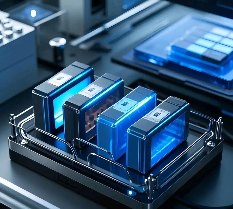
Electrochemical working principle. I explain the operation of a semi-solid-state cell in macroscopic terms exactly as I would explain a conventional lithium-ion cell. During charge, lithium ions deintercalate from the positive electrode, migrate through the hybrid electrolyte and functional separator, and intercalate into the negative electrode. During discharge, the reverse process occurs. Electrons move through the external circuit, producing current. This is the well-known rocking-chair mechanism. However, at the microscopic level, I observe a more complex transport picture. The semi-solid-state cell exhibits multi-pathway ion conduction. One fraction of lithium ions moves through residual liquid channels. Another fraction hops along polymer chains or inorganic crystal lattices. Ions also exchange between the solid and liquid phases at internal interfaces. In my view, this multi-pathway behavior is the key reason why a semi-solid-state cell can maintain useful rate capability even when the liquid content is low.
$$ \sigma_{\text{eff}} = \phi_l \sigma_l + \phi_s \sigma_s + \sigma_{\text{interface}} $$
In the expression above, I use \(\sigma_{\text{eff}}\) to denote the effective ionic conductivity of the hybrid electrolyte, \(\phi_l\) and \(\phi_s\) for the volume fractions of liquid and solid phases, \(\sigma_l\) and \(\sigma_s\) for their respective intrinsic conductivities, and \(\sigma_{\text{interface}}\) for the additional contribution from interfacial ion exchange. I find this simple additive model useful for explaining why the semi-solid-state cell can outperform a pure solid polymer electrolyte at room temperature. The liquid phase fills grain boundaries and electrode pores, while the solid phase provides mechanical strength and safety. The solid state cell therefore benefits from both phases rather than being limited by one.
I also consider the temperature dependence of ionic conductivity. In a semi-solid-state cell, ion transport often follows an Arrhenius relationship, especially when the polymer or inorganic phase dominates. I use the following expression to describe this behavior:
$$ \sigma(T) = \sigma_0 \exp\left(-\frac{E_a}{k_B T}\right) $$
Here, \(\sigma_0\) is a pre-exponential factor, \(E_a\) is the activation energy for ion transport, \(k_B\) is the Boltzmann constant, and \(T\) is absolute temperature. In my evaluation, the semi-solid-state cell benefits from a lower effective activation energy than a dry solid polymer electrolyte because the liquid phase provides a low-barrier pathway. This is one of the most important electrochemical advantages of the semi-solid-state cell over an early-stage all-solid-state cell. The solid state cell does not need to abandon liquid entirely to achieve improved performance; it needs to use liquid strategically.
Key material systems. I now turn to the material systems that make the semi-solid-state cell practical. In my view, the electrolyte is the most critical material because it determines ionic conductivity, electrochemical window, thermal stability, and interfacial compatibility. I classify electrolytes into polymer electrolytes, oxide solid electrolytes, and hybrid composites. Polymer electrolytes based on polyethylene oxide offer good flexibility and interfacial contact, but their room-temperature ionic conductivity is often too low, typically in the range of \(10^{-7}\) to \(10^{-5}\ \text{S cm}^{-1}\). I have seen two main modification strategies improve this. The first is plasticization with solvents such as propylene carbonate to reduce crystallinity and form a gel-like phase, raising room-temperature conductivity above \(10^{-3}\ \text{S cm}^{-1}\). The second is compositing with inorganic particles to disrupt polymer crystallization and reinforce mechanical strength. Both strategies are directly relevant to the semi-solid-state cell.
| Electrolyte family | Representative material | Room-temperature ionic conductivity | Main advantage | Main limitation |
|---|---|---|---|---|
| Solid polymer electrolyte | Polyethylene oxide | \(10^{-7}\) to \(10^{-5}\ \text{S cm}^{-1}\) | Flexible, good interfacial contact | Low conductivity, often needs elevated temperature |
| Gel polymer electrolyte | PVDF-HFP or PMMA with liquid electrolyte | \(10^{-4}\) to \(10^{-3}\ \text{S cm}^{-1}\) | High conductivity, shape flexibility | Residual liquid may still pose safety concerns |
| Oxide solid electrolyte | LLZO or LATP | \(10^{-4}\ \text{S cm}^{-1}\) for LLZO | High chemical stability, wide electrochemical window | Brittle, poor solid-solid contact |
| Composite solid electrolyte | Polymer plus inorganic filler | \(10^{-5}\) to \(10^{-3}\ \text{S cm}^{-1}\) | Balances flexibility and mechanical strength | Processing complexity, filler dispersion |
| In-situ cured electrolyte | Monomer, initiator, lithium salt, solvent | \(10^{-4}\) to \(10^{-3}\ \text{S cm}^{-1}\) | Excellent interfacial wetting before curing | Curing control and uniformity challenges |
In my analysis, oxide solid electrolytes such as garnet-type lithium lanthanum zirconium oxide and NASICON-type lithium aluminum titanium phosphate are attractive because they are chemically stable and relatively insensitive to air humidity. Their ionic conductivity can reach \(10^{-4}\ \text{S cm}^{-1}\), which is competitive with liquid electrolytes in some configurations. However, they are hard and brittle, and their solid-solid interfacial contact with electrodes is a major challenge. In a semi-solid-state cell, I prefer to use them as active fillers in a composite electrolyte or as coatings on a separator. This approach allows me to exploit their high conductivity and mechanical strength without requiring full solid-solid contact throughout the entire cell. The solid state cell therefore gains from oxide materials even when they are not the sole electrolyte.
Electrode materials for semi-solid-state cells. I have evaluated both negative and positive electrode options. For the negative electrode, graphite remains the incumbent because it is cheap, stable, and compatible with existing manufacturing. Silicon-based materials offer much higher capacity, but they undergo large volume changes during cycling. I have observed that the solid electrolyte phase in a semi-solid-state cell can buffer some of this expansion and help maintain particle contact. Lithium metal is even more attractive because its theoretical specific capacity is \(3860\ \text{mA h g}^{-1}\), compared with \(372\ \text{mA h g}^{-1}\) for graphite. If the hybrid electrolyte can suppress dendrite growth, lithium metal becomes a realistic negative electrode for a semi-solid-state cell. The solid state cell thus offers a route to lithium metal anodes without requiring a fully ceramic electrolyte.
$$ C_{\text{Li}} = 3860\ \text{mA h g}^{-1} $$
$$ C_{\text{graphite}} = 372\ \text{mA h g}^{-1} $$
For the positive electrode, I favor high-nickel layered oxides and high-voltage materials because they increase cell energy density. High-nickel NCM materials such as NCM 811 provide high specific capacity, while high-voltage spinels and phosphates can raise the average discharge voltage. The hybrid electrolyte in a semi-solid-state cell often has a wider electrochemical stability window than a purely liquid electrolyte, which allows these high-voltage positive electrodes to operate more stably. In my view, this is a direct benefit of the solid state cell approach. I can express the cell energy density as follows:
$$ E_m = \frac{C_{\text{cell}} V_{\text{avg}}}{m_{\text{cell}}} $$
Here, \(E_m\) is specific energy, \(C_{\text{cell}}\) is cell capacity, \(V_{\text{avg}}\) is average discharge voltage, and \(m_{\text{cell}}\) is cell mass. In my modeling, the semi-solid-state cell improves \(E_m\) by enabling higher-capacity electrodes and by reducing inactive liquid electrolyte mass. It also improves safety by reducing flammable liquid content. I therefore see the semi-solid-state cell as a balanced solid state cell design rather than a single-metric optimization.
| Electrode | Material class | Typical capacity or potential | Benefit in a semi-solid-state cell | Challenge |
|---|---|---|---|---|
| Negative | Graphite | \(372\ \text{mA h g}^{-1}\) | Mature, low cost, stable | Limited energy density |
| Negative | Silicon-carbon composite | High capacity, often above \(1000\ \text{mA h g}^{-1}\) | Higher energy density | Volume expansion, particle cracking |
| Negative | Lithium metal | \(3860\ \text{mA h g}^{-1}\) | Ultimate anode capacity | Dendrite growth, interfacial reactivity |
| Positive | NCM 811 | High nickel layered oxide | High capacity, high voltage | Surface instability, gas generation |
| Positive | Lithium iron phosphate | Olivine structure | Excellent safety and cycle life | Lower energy density |
| Positive | High-voltage spinel or phosphate | Elevated operating potential | Higher cell voltage | Electrolyte oxidation, interfacial degradation |
Performance comparison and trade-offs. I frequently compare the semi-solid-state cell with conventional liquid lithium-ion cells and all-solid-state cells. In my experience, the semi-solid-state cell occupies a performance window that is highly attractive for near-term products. Its energy density can range from about 160 to 400 Wh kg\(^{-1}\), which is higher than many conventional cells and sufficient for long-range electric vehicles. Its ionic conductivity typically falls between \(10^{-4}\) and \(10^{-3}\ \text{S cm}^{-1}\), which is lower than a liquid electrolyte but adequate for many practical charge and discharge rates. Its safety is significantly better than a liquid cell because the flammable liquid content is reduced and the solid phase suppresses leakage and dendrite penetration. Its manufacturing cost is lower than that of an all-solid-state cell because it can be produced on modified existing lines. In my judgment, this combination makes the semi-solid-state cell the most commercially credible solid state cell for the next five to ten years.
| Performance indicator | Conventional liquid lithium-ion cell | Semi-solid-state cell | All-solid-state cell |
|---|---|---|---|
| Specific energy | 150 to 300 Wh kg\(^{-1}\) | 160 to 400 Wh kg\(^{-1}\) | Above 500 Wh kg\(^{-1}\) target |
| Ionic conductivity | Around \(10^{-2}\ \text{S cm}^{-1}\) | \(10^{-4}\) to \(10^{-3}\ \text{S cm}^{-1}\) | \(10^{-7}\) to \(10^{-2}\ \text{S cm}^{-1}\), interface limited |
| Safety | Lower, flammable liquid and leakage risk | Higher, reduced liquid and dendrite suppression | Highest, no flammable liquid |
| Manufacturing cost | Low, mature process | Moderate, compatible with existing lines | High, new process and equipment |
| Industrial status | Fully mature | Early commercialization | Research and pilot scale |
| Interface challenge | Solid-electrolyte interphase instability | Solid-liquid and solid-solid mixed interfaces | Poor solid-solid contact and high impedance |
I also use several quantitative metrics to compare interfacial and transport behavior. The interfacial resistance of a semi-solid-state cell can be expressed as follows:
$$ R_{\text{int}} = \frac{\rho_{\text{int}}}{A} $$
where \(R_{\text{int}}\) is interfacial resistance, \(\rho_{\text{int}}\) is specific interfacial resistivity, and \(A\) is contact area. In my analysis, the semi-solid-state cell reduces \(R_{\text{int}}\) relative to an all-solid-state cell because the residual liquid phase increases effective contact area and fills voids. However, \(R_{\text{int}}\) remains higher than in a conventional liquid cell because the solid phase introduces additional boundaries. I therefore view interface engineering as the most important lever for improving the semi-solid-state cell. The solid state cell will not reach its full potential until these hybrid interfaces are understood and controlled at the nanoscale.
Another metric I track is the lithium-ion transference number, defined as:
$$ t_{\text{Li}^+} = \frac{I_{\text{Li}^+}}{I_{\text{total}}} $$
A higher \(t_{\text{Li}^+}\) means that a larger fraction of the total current is carried by lithium ions, which reduces concentration polarization and improves rate capability. In a semi-solid-state cell, I aim for a high transference number by designing anion-immobilizing polymer chains or by using inorganic fillers that interact selectively with lithium ions. This is a clear example of how the solid state cell can be optimized through molecular and interfacial design rather than through simple material substitution.
Safety and dendrite suppression. I consider safety to be one of the strongest arguments for the semi-solid-state cell. Conventional liquid electrolytes are flammable, volatile, and prone to leakage. When a cell undergoes thermal runaway, the liquid electrolyte provides fuel and can accelerate propagation. In a semi-solid-state cell, the liquid content is reduced to a controlled fraction, and the solid or gel phase acts as a physical barrier. The functional separator coated with inorganic solid electrolyte can raise thermal shrinkage temperature from around 120 °C to above 200 °C and increase tensile strength by 30% to 50%. These improvements directly reduce the probability of internal short circuits. In my view, the semi-solid-state cell is not merely a higher-energy cell; it is a safer solid state cell that can be deployed at scale.
| Safety feature | Conventional liquid cell | Semi-solid-state cell | Mechanistic reason |
|---|---|---|---|
| Flammable liquid content | High | Reduced to 5% to 15% by mass | Less fuel for thermal runaway |
| Leakage risk | Significant | Low | Gel or solid phase immobilizes liquid |
| Thermal shrinkage of separator | Around 120 °C | Above 200 °C with inorganic coating | Ceramic coating enhances dimensional stability |
| Dendrite penetration | Possible | Suppressed | Mechanical modulus and physical barrier |
| Internal short circuit probability | Higher | Lower | Improved separator strength and solid phase |
I model dendrite suppression using a critical current density criterion. In simplified form, the critical current density \(J_{\text{crit}}\) depends on the effective modulus, surface energy, and characteristic defect size:
$$ J_{\text{crit}} \propto \frac{\sigma_{\text{eff}} \gamma}{r L} $$
Here, \(\sigma_{\text{eff}}\) is the effective mechanical modulus, \(\gamma\) is surface energy, \(r\) is a characteristic defect radius, and \(L\) is a length scale. In my interpretation, the semi-solid-state cell raises \(J_{\text{crit}}\) by increasing \(\sigma_{\text{eff}}\) through the solid phase while maintaining good interfacial contact through the liquid phase. This dual effect is precisely why the semi-solid-state cell can support lithium metal or silicon-rich anodes better than a conventional liquid cell. The solid state cell therefore becomes safer and more energy-dense at the same time.
Manufacturing and industrialization. I have studied the industrialization path of the semi-solid-state cell closely, and I believe its greatest practical advantage is compatibility with existing lithium-ion manufacturing. The electrode coating, calendering, slitting, stacking or winding, electrolyte filling, and formation steps can all be adapted. The main changes are in electrolyte formulation, curing or gelation steps, and separator coating. This means that a manufacturer can transition from a conventional liquid cell to a semi-solid-state cell with moderate capital investment. By contrast, an all-solid-state cell often requires high-pressure sintering, dry-room processing, and entirely new stacking and packaging methods. In my assessment, this difference in capital intensity is decisive for near-term commercialization. The semi-solid-state cell allows the solid state cell concept to enter the market without waiting for a complete manufacturing revolution.
| Process step | Conventional liquid cell | Semi-solid-state cell | All-solid-state cell |
|---|---|---|---|
| Electrode slurry preparation | Mature | Compatible with minor changes | Often requires new binder and solvent systems |
| Coating and calendering | Mature | Compatible | Requires precise thickness and pressure control |
| Separator | Polyolefin membrane | Ceramic-coated functional separator | Often no separator, solid electrolyte layer |
| Electrolyte filling | Liquid injection | Precursor injection and in-situ curing or gelation | Solid electrolyte integration before stacking |
| Formation and aging | Standard | Adapted for gel or composite formation | High-pressure and specialized formation |
| Capital expenditure | Low | Moderate | High |
Commercialization status and trends. In my observation, the semi-solid-state cell has moved beyond concept validation. By the mid-2020s, several battery developers and automotive brands have announced vehicles or storage products using semi-solid-state cells. I have seen claims of battery packs with capacities around 150 kWh and driving ranges exceeding 1,000 km under light-vehicle test cycles. These products often combine gel polymer electrolytes with silicon-carbon negative electrodes. I do not need to name specific companies to recognize the trend: the semi-solid-state cell is entering early commercialization, and the solid state cell is no longer a purely laboratory concept. In my view, the first wave of semi-solid-state cell products will target premium electric vehicles, where customers value range, safety, and fast charging. The second wave will target mass-market vehicles as costs decline and manufacturing yields improve.
$$ \text{Range} \approx \frac{E_{\text{pack}}}{c_{\text{consumption}}} $$
In the expression above, \(E_{\text{pack}}\) is usable pack energy and \(c_{\text{consumption}}\) is vehicle energy consumption per unit distance. I use this relationship to explain why a semi-solid-state cell with higher specific energy can directly extend vehicle range without changing vehicle architecture. The solid state cell therefore offers a systems-level benefit, not just a materials-level improvement.
Future research directions. I identify four major research directions for the semi-solid-state cell. First, interface engineering must be improved. I need to reduce solid-liquid and solid-solid interfacial resistance, stabilize interfaces over thousands of cycles, and prevent side reactions. Surface coating of electrodes, optimized electrolyte additives, and gradient electrolyte designs are promising. Second, new solid electrolyte materials with higher ionic conductivity, wider electrochemical windows, and lower cost are needed. Third, lithium metal negative electrodes must achieve long cycle life. Although the semi-solid-state cell suppresses dendrites better than a liquid cell, thousands of cycles remain challenging. I see promise in alloy anodes, artificial solid-electrolyte interphases, and electrolyte formulations that promote uniform lithium deposition. Fourth, cost reduction must continue. The solid state cell will only achieve mass adoption when its cost per kilowatt-hour approaches that of conventional lithium-ion cells. I therefore track material cost, processing yield, and scale-up efficiency as key indicators.
| Research direction | Objective | Key strategy | Expected impact |
|---|---|---|---|
| Interface engineering | Lower interfacial resistance and improve stability | Electrode coating, electrolyte additives, gradient design | Higher rate capability and longer cycle life |
| New solid electrolytes | Higher conductivity, wider window, lower cost | Composite, hybrid, and doped inorganic systems | Better performance and manufacturability |
| Lithium metal stability | Suppress dendrites and extend cycle life | Alloy anodes, artificial interphases, pressure control | Higher energy density and safety |
| Cost reduction | Approach conventional lithium-ion cost | Material substitution, process simplification, scale-up | Mass-market adoption |
I also emphasize the importance of standardized testing for the semi-solid-state cell. Because the boundary between semi-solid, quasi-solid, and all-solid-state is quantitative, I need reliable methods to measure liquid content, ionic conductivity, interfacial resistance, and mechanical modulus. I use vacuum drying and mass loss measurements, electrochemical impedance spectroscopy, and pressure-controlled cycling to characterize these cells. Without standardized metrics, comparisons between different solid state cell designs become unreliable. In my view, the industry should adopt transparent reporting of liquid mass fraction, electrolyte composition, test temperature, and stack pressure. This will accelerate the solid state cell transition by allowing reproducible benchmarking.
$$ Q_{\text{ret}} = \frac{Q_N}{Q_0} \times 100\% $$
In the equation above, \(Q_{\text{ret}}\) is capacity retention, \(Q_N\) is discharge capacity after \(N\) cycles, and \(Q_0\) is initial discharge capacity. I use this metric to compare cycle life across semi-solid-state cell designs. A high-performing semi-solid-state cell should retain more than 80% of its initial capacity after 1,000 to 2,000 cycles, depending on application. This target is demanding but achievable with optimized interfaces and electrode materials.
Comparative advantages and remaining gaps. In my overall assessment, the semi-solid-state cell offers the best near-term balance of energy density, safety, cost, and manufacturability. It is not the final answer, but it is the most practical solid state cell for the next decade. I summarize its advantages as follows: it reduces flammable liquid content, it suppresses dendrite growth, it enables high-capacity electrodes, it extends driving range, and it can be produced on modified existing lines. Its remaining gaps include lower ionic conductivity than liquid electrolytes, higher interfacial resistance than conventional cells, limited long-term cycling data for lithium metal anodes, and higher cost than mature liquid cells. I do not ignore these gaps. Instead, I see them as focused research targets. The solid state cell will advance through the semi-solid-state cell, not around it.
| Dimension | Advantage of semi-solid-state cell | Remaining gap | My research priority |
|---|---|---|---|
| Energy density | Higher than conventional liquid cells | Below ultimate all-solid-state target | High-capacity electrodes and thin electrolytes |
| Safety | Reduced liquid, better thermal stability | Residual liquid can still react | Nonflammable liquid and robust solid phase |
| Ionic conductivity | Adequate for many applications | Lower than liquid electrolyte | Composite and hybrid electrolyte design |
| Cycle life | Improving rapidly | Lithium metal cycling still limited | Interface protection and alloy anodes |
| Cost | Lower than all-solid-state cell | Higher than mature liquid cell | Material and process cost reduction |
| Manufacturing | Compatible with existing lines | New curing and coating steps | Process integration and yield improvement |
Mathematical framing of cost and performance. I often use a cost-performance ratio to compare technologies. A simple expression is:
$$ \eta_{\text{cost}} = \frac{E_m}{C_{\text{kWh}}} $$
Here, \(\eta_{\text{cost}}\) represents energy delivered per unit cost, \(E_m\) is specific energy, and \(C_{\text{kWh}}\) is cost per kilowatt-hour. In my analysis, the semi-solid-state cell improves \(\eta_{\text{cost}}\) relative to an all-solid-state cell because its manufacturing cost is lower while its energy density is still attractive. It also improves \(\eta_{\text{cost}}\) relative to a conventional liquid cell in applications where safety and range are valued. I therefore view the semi-solid-state cell as an economically rational intermediate step toward the all-solid-state cell. The solid state cell does not need to be perfect to be valuable; it needs to be better than the incumbent on the metrics that matter to customers.
I also consider the trade-off between liquid fraction and ionic conductivity. In a simplified percolation model, I can write:
$$ \sigma_{\text{eff}} \propto (\phi_l – \phi_{l,c})^\beta $$
where \(\phi_{l,c}\) is the critical liquid volume fraction for percolation and \(\beta\) is an exponent. In my interpretation, this relationship explains why a small amount of liquid can dramatically improve conductivity when it forms continuous pathways. The semi-solid-state cell is designed to stay above this percolation threshold while keeping total liquid mass low. This is a delicate balance, and it is one of the reasons why electrolyte formulation is so important. The solid state cell must be engineered at the microscale to achieve macroscale performance.
Outlook. Looking forward, I expect the semi-solid-state cell to become a mainstream technology for long-range electric vehicles, electric aviation, and grid storage. In electric vehicles, it will extend range and improve safety. In electric aviation, its high energy density and reduced flammability are especially valuable. In grid storage, its cycle life and thermal stability will support large-scale deployment. I also expect the semi-solid-state cell to serve as a learning platform for the all-solid-state cell. The knowledge gained in hybrid electrolyte formulation, interface control, and scalable manufacturing will directly transfer to future all-solid-state designs. In my view, the solid state cell era will begin with semi-solid-state cells, and those cells will enable the eventual all-solid-state cell.
I conclude that the semi-solid-state cell is not a temporary distraction but a strategically essential technology. It addresses the safety and energy-density limits of conventional liquid lithium-ion cells while avoiding the severe manufacturing and interfacial barriers of all-solid-state cells. It uses a solid-liquid hybrid electrolyte to achieve multi-pathway ion transport, dendrite suppression, and improved thermal stability. It is compatible with high-nickel positive electrodes, silicon-carbon negative electrodes, and potentially lithium metal. It can be produced on modified existing lines, which lowers the barrier to industrialization. I therefore believe that the semi-solid-state cell will dominate the advanced battery market for the next five to ten years. The solid state cell will continue to evolve, and the semi-solid-state cell will be remembered as the first commercially successful expression of that evolution. My final assessment is that the transition to solid state cell technology will be gradual, hybrid, and highly engineered, and the semi-solid-state cell is the critical enabler of that transition.