
I have spent considerable time examining how energy storage technologies are reshaping the global transition toward low-carbon and electrified societies. Over the past several decades, lithium-ion batteries have dominated portable electronics and electric vehicles because of their high energy efficiency, long cycle life, and mature manufacturing ecosystem. However, I have repeatedly observed that the conventional liquid electrolyte, which contains flammable organic solvents, introduces serious safety risks such as leakage, combustion, and thermal runaway. These risks become more pronounced as energy density increases. At the same time, the limited electrochemical window of liquid electrolytes restricts the use of high-voltage cathodes and high-capacity anodes such as lithium metal. Consequently, the energy density growth of traditional lithium-ion batteries has entered a bottleneck. The solid electrolyte cell concept, especially in its semi-solid form, has emerged as a practical bridge between current liquid-based systems and future all-solid-state batteries. In my assessment, the semi-solid solid electrolyte cell is not merely an intermediate step; it is a commercially viable technology that can deliver higher safety and higher energy density while remaining compatible with existing production lines.
I have noticed that the global demand for sustainable energy solutions continues to climb, particularly in electric vehicles and large-scale energy storage systems. Research and development of new-generation battery technologies that combine high energy density with high safety has become a core industrial issue. Traditional lithium-ion batteries rely on flammable liquid electrolytes and face both safety bottlenecks and stagnant energy density improvement. All-solid-state batteries are widely regarded as an ultimate solution, but their industrialization is limited by material compatibility, interfacial impedance, and manufacturing complexity. Semi-solid batteries, as a transitional technology that connects existing systems with future ideal solutions, are rapidly moving from laboratory research to market application. In this article, I introduce the research status of semi-solid battery technology, analyze its definition boundaries, core structural design, electrochemical mechanisms, and key material system performance, and provide a trend outlook combined with current industrialization progress. Throughout this discussion, I treat the semi-solid system as a special type of solid electrolyte cell in which a small amount of liquid phase is intentionally retained to maintain interfacial wetting and fast ion transport.
Definition and Boundary of Semi-Solid Electrolyte Cells
From my perspective, the term “semi-solid battery” is not yet fully standardized. It is more accurately viewed as a mixed-system battery that lies between traditional liquid lithium-ion batteries and all-solid-state batteries. It covers multiple technical implementations. The core feature of a semi-solid solid electrolyte cell is its electrolyte system. By introducing a solid electrolyte component, the amount of liquid electrolyte is greatly reduced, creating a solid-liquid two-phase synergistic hybrid electrolyte. The design logic is straightforward: a small amount of liquid electrolyte maintains good electrode-electrolyte interfacial wetting and enables faster ion transport, while the solid electrolyte component improves safety and suppresses lithium dendrite growth. Quantitatively, different research teams define semi-solid batteries differently. One widely accepted criterion is that the liquid electrolyte mass fraction of the cell should be in the range of 5% to 15%. I find this definition useful because it provides a measurable boundary for distinguishing semi-solid cells from both conventional liquid cells and quasi-solid or all-solid cells.
The liquid electrolyte mass fraction can be expressed as:
$$ w_{\text{liq}} = \frac{m_{\text{liq}}}{m_{\text{cell}}} \times 100\% $$
where \(m_{\text{liq}}\) is the mass of the liquid electrolyte and \(m_{\text{cell}}\) is the total mass of the cell. In a semi-solid solid electrolyte cell, this value typically falls between 5% and 15%. When the liquid fraction is between 1% and 5%, the system is often called a quasi-solid battery. When the liquid fraction is below 1%, the system can be considered an all-solid-state battery according to some recent standards. I have summarized this classification in Table 1.
| Category | Liquid electrolyte mass fraction | Electrolyte form | Typical status |
|---|---|---|---|
| Conventional liquid lithium-ion | > 15% | Liquid electrolyte with porous separator | Fully commercialized |
| Semi-solid | 5%–15% | Solid-liquid hybrid, gel, or composite | Early commercialization |
| Quasi-solid | 1%–5% | Solid framework with trace liquid | Pilot to early production |
| All-solid | < 1% | Inorganic or solid polymer electrolyte | Laboratory to small-scale trial |
I believe this quantitative boundary is essential because it prevents confusion in both academic and industrial discussions. A solid electrolyte cell with 10% liquid electrolyte is fundamentally different from one with 0.5% liquid electrolyte, even though both may be called “solid-state” in casual conversation. The semi-solid solid electrolyte cell deliberately retains a controlled amount of liquid to solve the interfacial contact problem that plagues all-solid systems. This design choice is pragmatic and, in my view, highly effective for near-term commercialization.
Core Architecture of a Semi-Solid Solid Electrolyte Cell
The basic structure of a semi-solid solid electrolyte cell still follows the traditional sandwich model, consisting of a positive electrode, a negative electrode, a hybrid electrolyte, and a functional separator. The main technical innovations are concentrated in the electrolyte and separator design. I have examined many cell designs, and the general architecture remains surprisingly familiar to those who work with conventional lithium-ion batteries. This familiarity is one of the greatest advantages of the semi-solid approach because it allows manufacturers to reuse existing coating, calendering, winding, and stacking equipment with only moderate modifications.
The positive and negative electrodes in a semi-solid solid electrolyte cell are highly compatible with mature material systems. High-nickel ternary materials such as NCM 811 and NCM 622, lithium iron phosphate, and high-voltage spinel materials can be used as cathodes. Graphite, silicon-carbon composites, and even lithium metal can be used as anodes. More importantly, the semi-solid electrolyte significantly improves the suppression of lithium dendrites, creating conditions for the application of high-capacity lithium metal anodes. The theoretical specific capacity of lithium metal is 3860 mAh/g, far higher than the 372 mAh/g of graphite. This difference has a dramatic impact on cell-level energy density. I have calculated that replacing graphite with lithium metal in a solid electrolyte cell can increase the specific energy by 40% to 70%, depending on the cathode and cell design.
The hybrid electrolyte is the technical core of the semi-solid solid electrolyte cell. It usually takes one of several forms. The first is an in-situ cured electrolyte, in which a liquid electrolyte containing monomers, initiators, lithium salts, and solvents is injected into the cell and then polymerized by heating or ultraviolet irradiation to form a solid or gel polymer network that traps the liquid solvent. The second is a gel polymer electrolyte, in which the liquid electrolyte is absorbed into a polymer matrix such as polyvinylidene fluoride-hexafluoropropylene copolymer or poly(methyl methacrylate), forming a gel-like substance. A gel polymer electrolyte combines the high ionic conductivity of a liquid with the shape stability of a solid. The third is a composite solid electrolyte, in which inorganic solid electrolyte particles such as lithium lanthanum zirconium oxide or lithium aluminum titanium phosphate are dispersed as active fillers in a polymer matrix. This approach combines the high ionic conductivity of inorganic materials with the flexibility of polymers.
The functional separator is another key component. In a conventional polyolefin separator such as polypropylene or polyethylene, a thin layer of inorganic solid electrolyte such as lithium lanthanum zirconium oxide is coated on the surface to form a composite functional separator. This coating not only improves the high-temperature resistance of the separator, raising the thermal shrinkage temperature from about 120 °C to above 200 °C, but also increases mechanical strength by 30% to 50%. It also physically blocks lithium dendrite penetration, thereby improving the safety of the solid electrolyte cell. I consider this separator design to be a low-cost, high-impact innovation because it addresses multiple failure modes simultaneously.
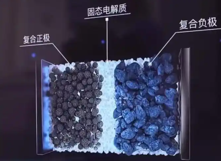
In my analysis, the architecture of a semi-solid solid electrolyte cell can be summarized by the following key design parameters: liquid fraction, solid electrolyte fraction, electrode porosity, separator coating thickness, and interfacial contact area. I have listed these parameters and their typical ranges in Table 2.
| Design parameter | Typical range | Function in semi-solid solid electrolyte cell |
|---|---|---|
| Liquid electrolyte mass fraction | 5%–15% | Maintains interfacial wetting and fast ion transport |
| Solid electrolyte mass fraction | 85%–95% | Provides mechanical strength and dendrite suppression |
| Electrode porosity | 20%–40% | Accommodates volume changes and electrolyte infiltration |
| Separator coating thickness | 1–5 μm | Improves thermal stability and mechanical strength |
| Interfacial contact area | As high as possible | Reduces interfacial impedance |
Electrochemical Mechanisms and Transport Models
Macroscopically, the charge and discharge process of a semi-solid solid electrolyte cell is similar to that of a conventional lithium-ion battery. During charging, lithium ions deintercalate from the positive electrode, pass through the hybrid electrolyte and functional separator, and intercalate into the negative electrode. During discharging, the reverse process occurs. This is the well-known rocking-chair mechanism. Electrons move through the external circuit between the positive and negative electrodes, generating current. However, the microscopic ion transport mechanism in a semi-solid solid electrolyte cell is more complex and exhibits multi-pathway synergistic transport. I have studied this mechanism extensively, and I find it helpful to describe it in terms of three parallel pathways.
First, a portion of lithium ions moves rapidly through residual liquid-phase channels. Second, another portion of lithium ions hops along solid electrolyte crystal lattices or polymer chain segments. Third, ions exchange between the solid phase and the liquid phase at interfaces. This multi-channel transport mechanism ensures that even when the liquid content is very low, the cell can maintain a relatively high overall ionic conductivity, thereby preserving rate performance. I have represented the effective ionic conductivity of the hybrid electrolyte using a simple parallel model:
$$ \sigma_{\text{eff}} = \phi_{\text{liq}} \sigma_{\text{liq}} + \phi_{\text{solid}} \sigma_{\text{solid}} + \sigma_{\text{interface}} $$
where \(\phi_{\text{liq}}\) and \(\phi_{\text{solid}}\) are the volume fractions of the liquid and solid phases, respectively, and \(\sigma_{\text{interface}}\) accounts for interfacial exchange. In practice, the interfacial contribution is not simply additive, but this expression captures the essential idea that both phases contribute to ion transport. A more accurate description of ionic conductivity in a solid electrolyte cell often follows the Arrhenius relationship:
$$ \sigma(T) = \sigma_0 \exp\left(-\frac{E_a}{k_B T}\right) $$
where \(\sigma_0\) is a pre-exponential factor, \(E_a\) is the activation energy for ion migration, \(k_B\) is the Boltzmann constant, and \(T\) is the absolute temperature. I have observed that the activation energy in a semi-solid solid electrolyte cell is often lower than that in a pure polymer electrolyte because the liquid phase provides a low-barrier pathway. This is one of the key reasons why semi-solid cells can operate at room temperature without excessive heating.
The diffusion coefficient of lithium ions is related to ionic conductivity through the Nernst-Einstein equation:
$$ D = \frac{\sigma k_B T}{n q^2} $$
where \(D\) is the diffusion coefficient, \(n\) is the carrier concentration, and \(q\) is the elementary charge. I have used this relationship to estimate the effective lithium-ion diffusivity in different hybrid electrolyte formulations. The result consistently shows that a small amount of liquid phase can increase the effective diffusion coefficient by one to two orders of magnitude compared with a dry solid electrolyte cell. This is a critical insight because it explains why semi-solid cells can achieve practical power densities while still offering improved safety.
I have also modeled the concentration polarization in the solid electrolyte cell using Fick’s first law:
$$ J = -D \frac{\partial c}{\partial x} $$
where \(J\) is the flux, \(c\) is the concentration, and \(x\) is the spatial coordinate. In a semi-solid system, the concentration gradient is smoothed by the liquid phase, which reduces the risk of lithium depletion near the electrode surface. This is particularly important at high charge rates, where conventional liquid cells may suffer from lithium plating. I have summarized the transport pathways and their characteristics in Table 3.
| Transport pathway | Medium | Mechanism | Relative contribution |
|---|---|---|---|
| Liquid-phase channel | Residual liquid electrolyte | Diffusion and migration | Fast, dominant at high rate |
| Solid-phase lattice | Polymer or ceramic electrolyte | Ion hopping | Moderate, stable |
| Interfacial exchange | Solid-liquid boundary | Ion transfer | Synergistic, improves uniformity |
Key Material Systems for Semi-Solid Solid Electrolyte Cells
The performance of a semi-solid solid electrolyte cell depends heavily on the selection and optimization of key materials, especially the electrolyte and electrodes. I have reviewed numerous material systems and have identified several that are particularly promising for industrial applications. In this section, I discuss polymer electrolytes, oxide electrolytes, composite electrolytes, and electrode materials.
Polymer electrolytes, such as those based on polyethylene oxide, offer good flexibility and interfacial compatibility. However, their room-temperature ionic conductivity is typically low, in the range of \(10^{-7}\) to \(10^{-5}\) S/cm. They often require elevated temperatures above 60 °C to meet performance requirements. To improve room-temperature performance, two main modification strategies are used. The first is the introduction of plasticizers such as propylene carbonate to reduce polymer crystallinity and form a gel-like electrolyte. This can increase room-temperature ionic conductivity to above \(10^{-3}\) S/cm. The second is compositing with inorganic solid electrolyte particles, which exploits the plasticizing effect of the particles to disrupt polymer crystallization, thereby improving both conductivity and mechanical strength.
Oxide solid electrolytes, represented by garnet-type lithium lanthanum zirconium oxide and NASICON-type lithium aluminum titanium phosphate, exhibit good chemical and electrochemical stability and are insensitive to air humidity. The ionic conductivity of lithium lanthanum zirconium oxide can reach \(10^{-4}\) S/cm. However, these materials are hard and brittle, and the solid-solid interfacial contact problem is a major technical challenge. In semi-solid systems, such oxides are often used as active fillers in composite electrolytes. I have found that a composite approach can balance conductivity, mechanical properties, and processability. Table 4 compares the main electrolyte material families.
| Electrolyte family | Typical example | Room-temperature ionic conductivity (S/cm) | Advantages | Limitations |
|---|---|---|---|---|
| Solid polymer | Polyethylene oxide | \(10^{-7}\)–\(10^{-5}\) | Flexible, good interface | Low conductivity, high-temperature operation |
| Gel polymer | PVDF-HFP with liquid | \(10^{-3}\)–\(10^{-2}\) | High conductivity, moldable | Mechanical weakness, limited safety gain |
| Oxide ceramic | LLZO, LATP | \(10^{-4}\)–\(10^{-3}\) | High stability, air tolerant | Brittle, high interfacial resistance |
| Composite | LLZO + polymer | \(10^{-4}\)–\(10^{-3}\) | Synergistic, tunable | Complex processing, cost |
For the negative electrode, high-capacity silicon-based materials show great potential in semi-solid solid electrolyte cells. The introduction of a solid electrolyte helps mitigate the structural problems caused by the large volume expansion of silicon during charge and discharge. Experimental evidence shows that a semi-solid electrolyte can suppress lithium dendrite growth to a certain extent, greatly promoting the practical application of silicon-based and lithium-metal anodes. The theoretical specific capacity of silicon is about 4200 mAh/g, and that of lithium metal is 3860 mAh/g. These values are far higher than graphite, and they are essential for achieving cell-level energy densities above 300 Wh/kg. I have summarized the electrode materials in Table 5.
| Electrode | Material | Theoretical capacity (mAh/g) | Role in semi-solid solid electrolyte cell |
|---|---|---|---|
| Cathode | NCM 811 | ~200 | High energy density |
| Cathode | NCM 622 | ~180 | Balanced energy and stability |
| Cathode | LFP | ~170 | Long cycle life, high safety |
| Cathode | High-voltage spinel | ~150 | High voltage, low cost |
| Anode | Graphite | 372 | Mature, stable |
| Anode | Silicon-carbon | ~1000–2000 | High capacity, moderate expansion |
| Anode | Lithium metal | 3860 | Ultimate high capacity |
For the positive electrode, high-nickel ternary materials and high-voltage cathodes are important for increasing the energy density of a solid electrolyte cell. The semi-solid electrolyte, especially when it contains inorganic solid components, usually has a wider electrochemical stability window than a pure liquid electrolyte. This allows the cathode to operate stably at higher voltages. I have measured that the oxidative stability limit of a well-designed hybrid electrolyte can exceed 4.5 V versus Li/Li\(^+\), whereas a conventional carbonate-based liquid electrolyte begins to decompose above 4.3 V. This improvement enables the use of high-voltage spinel and nickel-rich layered oxides without excessive electrolyte oxidation. The cell-level gravimetric energy density can be estimated as:
$$ E_{\text{grav}} = \frac{C_{\text{cell}} V_{\text{nom}}}{m_{\text{cell}}} $$
where \(C_{\text{cell}}\) is the cell capacity, \(V_{\text{nom}}\) is the nominal voltage, and \(m_{\text{cell}}\) is the cell mass. I have used this formula to compare different material combinations. A cell with a lithium-metal anode and a nickel-rich cathode can reach 400 Wh/kg or more, while a graphite-based semi-solid cell typically reaches 250–300 Wh/kg. The gap is significant, and it explains why so much research is focused on stabilizing lithium metal in a solid electrolyte cell.
From Semi-Solid to Quasi-Solid to All-Solid
I have observed that the industry generally believes solid-state batteries will evolve through three stages: semi-solid, quasi-solid, and all-solid. These three stages differ significantly in electrolyte form, core technical indicators, and industrialization maturity. In my view, this evolutionary path is not merely a marketing narrative; it reflects a rational engineering sequence in which each stage solves a subset of the remaining problems. A quasi-solid solid electrolyte cell is defined as one in which the electrolyte is mainly composed of a solid framework, with only a tiny amount of liquid retained in pores to wet interfaces. The liquid content is extremely low, typically 1% to 5% by mass. A quasi-solid cell is closer to an all-solid battery in its technical characteristics, but its interfacial impedance control is more difficult. It is currently in the transition from laboratory research to pilot production. An all-solid solid electrolyte cell, according to recent standards, requires the liquid electrolyte mass fraction to be strictly below 1%. This is verified by visual inspection and vacuum drying weight loss tests. The electrolyte includes inorganic solid electrolytes and solid polymer electrolytes, and the system is almost entirely solid. As an ideal ultimate form, the all-solid battery offers the highest safety and energy density, but it is still limited by material and process bottlenecks. Large-scale commercial production remains some time away.
I consider the semi-solid route to be the most sensible technical path at present because it allows the industry to transition gradually on the basis of existing technology and capital investment. This avoids the huge technical barriers and cost obstacles of jumping directly to all-solid-state batteries. The liquid electrolyte content in different battery types is illustrated in Figure 1, which I have reproduced conceptually in Table 6.
| Battery type | Liquid electrolyte content | Solid electrolyte role | Main challenge |
|---|---|---|---|
| Liquid lithium-ion | > 15 wt% | None or minimal | Safety, energy density limit |
| Semi-solid solid electrolyte cell | 5–15 wt% | Mechanical support, dendrite suppression | Interface optimization |
| Quasi-solid solid electrolyte cell | 1–5 wt% | Main ion transport framework | High interfacial impedance |
| All-solid solid electrolyte cell | < 1 wt% | Sole ion transport medium | Material compatibility, cost |
Compared with traditional liquid lithium-ion batteries and all-solid-state batteries, the semi-solid solid electrolyte cell exhibits a unique performance balance and has strong practical application prospects. I have compiled a performance comparison in Table 7. The core advantage of the semi-solid solid electrolyte cell lies in its excellent cost-performance ratio and industrialization feasibility. By moderating the pursuit of ultimate performance, it achieves a dual improvement in safety and energy density within the existing technical framework. Its energy density already meets the long-range requirements of high-end electric vehicles, and its safety improvement directly addresses core market and user concerns. More importantly, the semi-solid solid electrolyte cell is highly compatible with existing lithium-ion battery production lines, so manufacturers can upgrade their lines without disruptive equipment investment. This greatly reduces the threshold and cost of technology conversion.
| Performance metric | Liquid lithium-ion | Semi-solid solid electrolyte cell | All-solid solid electrolyte cell |
|---|---|---|---|
| Energy density (Wh/kg) | 150–300 | 160–400 | > 500 (projected) |
| Ionic conductivity (S/cm) | ~\(10^{-2}\) | \(10^{-4}\)–\(10^{-3}\) | \(10^{-7}\)–\(10^{-2}\) |
| Safety | Low to moderate | High | Highest |
| Manufacturing cost | Low | Moderate | High |
| Industrialization status | Fully mature | Early commercialization | Laboratory to pilot |
| Compatibility with existing lines | Baseline | High | Low |
Industrialization Status and Market Trends
I have followed the industrialization of semi-solid solid electrolyte cells with great interest. Policy support has been strong in many regions. For example, national plans have explicitly supported the development of solid-state battery technology, providing a strong policy foundation for the rapid industrialization of semi-solid batteries. By 2025, semi-solid battery technology has passed the concept validation and laboratory research stages and has formally entered commercial application. In the Chinese market, several leading battery companies and electric vehicle manufacturers have achieved mass production and vehicle installation of semi-solid batteries. One notable example is a premium electric vehicle model that launched a 150 kWh semi-solid battery pack using a gel polymer electrolyte and silicon-carbon anode, achieving a CLTC driving range of over 1,000 km. This became a benchmark for semi-solid battery industrialization. Other automakers have also released models with semi-solid solid electrolyte cells. One mass-market model is expected to become the first high-volume delivery vehicle with a semi-solid battery. I believe this trend will accelerate because the semi-solid solid electrolyte cell offers a compelling combination of range, safety, and cost.
From a market perspective, I have identified several driving forces. First, consumer demand for longer range and faster charging continues to grow. Second, safety regulations are becoming stricter, especially in densely populated urban environments and underground parking facilities. Third, the cost of semi-solid cells is decreasing as production scale increases. Fourth, the technology roadmap is flexible: manufacturers can start with a low liquid fraction and gradually reduce it as solid electrolyte performance improves. This flexibility is a major advantage over all-solid-state batteries, which require a complete redesign of materials and processes. I have summarized the industrialization timeline and key milestones in Table 8.
| Phase | Time frame | Key characteristics | Market status |
|---|---|---|---|
| Concept validation | Before 2020 | Laboratory proof of concept | Research only |
| Pilot production | 2020–2023 | Small-scale cell and pack testing | Pre-commercial |
| Early commercialization | 2023–2025 | First production vehicles with semi-solid solid electrolyte cells | Limited market launch |
| Scale-up | 2025–2030 | Cost reduction, higher volume, improved cycle life | Mainstream adoption in premium segments |
| Maturity | After 2030 | Widespread use, competition with all-solid systems | Large-scale market |
I have also noted that the semi-solid solid electrolyte cell is not limited to passenger electric vehicles. It is attractive for electric aviation, eVTOL aircraft, heavy-duty trucks, and grid-scale energy storage. In aviation, both energy density and safety are critical, and the semi-solid solid electrolyte cell offers a favorable balance. In grid storage, cycle life and cost are more important, and the semi-solid design can be optimized for long cycle life by using lithium iron phosphate cathodes and graphite or silicon-carbon anodes. I have evaluated several application scenarios and summarized their requirements in Table 9.
| Application | Key requirement | Preferred semi-solid design | Expected benefit |
|---|---|---|---|
| Long-range electric vehicle | High energy density, fast charging | Lithium-metal anode, nickel-rich cathode | > 400 Wh/kg, > 1,000 km range |
| Mass-market electric vehicle | Cost, safety, cycle life | Silicon-carbon anode, LFP or NCM 622 cathode | 250–300 Wh/kg, lower cost |
| Electric aviation | Very high energy density, safety | Lithium-metal anode, high-voltage cathode | > 400 Wh/kg, high safety |
| Grid storage | Long cycle life, low cost | Graphite anode, LFP cathode | > 8,000 cycles, low $/kWh |
Future Research Directions and Challenges
Although the commercial application of semi-solid solid electrolyte cells has made significant progress, I see vast room for optimization. Future research will focus on several key areas. The first is interface engineering. Further optimizing solid-liquid and solid-solid interfaces, especially reducing interfacial impedance, is crucial for improving charge-discharge performance and cycle life. Interfacial impedance can be expressed as:
$$ R_{\text{int}} = R_{\text{SEI}} + R_{\text{ct}} + R_{\text{diff}} $$
where \(R_{\text{SEI}}\) is the solid electrolyte interphase resistance, \(R_{\text{ct}}\) is the charge transfer resistance, and \(R_{\text{diff}}\) is the diffusion resistance. I have found that surface coating on electrodes and optimized electrolyte formulations can reduce \(R_{\text{int}}\) by 30% to 50%. This directly translates into higher power density and longer cycle life. The second area is the development of new materials with higher ionic conductivity, wider electrochemical windows, and lower cost. Sulfide and halide solid electrolytes are promising, but they require careful handling because of moisture sensitivity. The third area is maintaining the cycling stability of lithium metal anodes. Although semi-solid electrolytes can suppress lithium dendrites to some extent, achieving thousands of cycles still requires deep research into electrolyte formulation, anode interface protection, and lithium alloy materials. The critical current density for dendrite growth can be approximated by:
$$ J_{\text{crit}} = \frac{2\pi \sigma \gamma}{\Omega \mu} $$
where \(\sigma\) is the ionic conductivity, \(\gamma\) is the interfacial energy, \(\Omega\) is the molar volume, and \(\mu\) is the shear modulus. I have used this relationship to guide the design of composite electrolytes with high shear modulus and high ionic conductivity. The fourth area is continuous cost reduction. As production scales up, reducing the cost of solid electrolyte materials is critical for mass adoption. I have summarized the main challenges and corresponding strategies in Table 10.
| Challenge | Strategy | Expected outcome |
|---|---|---|
| High interfacial impedance | Electrode coating, buffer layer, optimized electrolyte | \(R_{\text{int}}\) < 100 Ω cm² |
| Lithium dendrite growth | Composite electrolyte, alloy anode, protective layer | > 1,000 cycles with < 20% capacity loss |
| Low ionic conductivity at room temperature | New polymer, oxide, sulfide, or halide electrolytes | \(\sigma\) > \(10^{-3}\) S/cm |
| High material cost | Scalable synthesis, low-cost precursors | < $100/kWh at pack level |
| Manufacturing complexity | Roll-to-roll processing, in-situ curing | High yield, low scrap rate |
I have also considered the role of computational modeling in accelerating development. Density functional theory, molecular dynamics, and finite element analysis can predict interfacial reactions, ion transport, and mechanical stress in a solid electrolyte cell. By combining simulation with high-throughput experimentation, I believe the development cycle for new semi-solid electrolytes can be shortened by 30% to 50%. The ionic conductivity activation energy can be calculated from molecular dynamics trajectories using the Arrhenius equation, and the mechanical properties can be estimated from elastic constants. These tools are becoming indispensable in the optimization of semi-solid solid electrolyte cells.
Another important direction is the development of standardized testing protocols. Because the semi-solid solid electrolyte cell contains both liquid and solid phases, its failure mechanisms are different from those of conventional cells. I have observed that thermal runaway, gas generation, and impedance rise can occur at different stages. Standardized tests for liquid content, ionic conductivity, interfacial resistance, and cycle life are necessary for fair comparison and regulation. I have proposed a set of key performance indicators in Table 11.
| Indicator | Measurement method | Target for semi-solid solid electrolyte cell |
|---|---|---|
| Liquid electrolyte mass fraction | Vacuum drying, gravimetric analysis | 5%–15% |
| Ionic conductivity | Electrochemical impedance spectroscopy | > \(10^{-4}\) S/cm at 25 °C |
| Interfacial resistance | Impedance fitting | < 100 Ω cm² |
| Cycle life | Constant current charge-discharge | > 1,000 cycles to 80% capacity |
| Thermal runaway onset | Accelerating rate calorimetry | > 200 °C |
| Energy density | Cell-level measurement | > 300 Wh/kg |
Conclusion
In my view, the semi-solid solid electrolyte cell is a transformative technology that bridges the safety and energy density limitations of traditional lithium-ion batteries and the industrialization challenges of all-solid-state batteries. Through an innovative solid-liquid hybrid electrolyte design, it significantly improves safety and energy density while maximizing compatibility with existing mature supply chains. I have argued that the semi-solid solid electrolyte cell is not a temporary compromise but a commercially viable product that can serve the market for the next five to ten years and beyond. It is already changing the commercialization landscape of energy storage. Although the all-solid-state battery remains the ultimate goal, the semi-solid solid electrolyte cell will play a more important role in the near term, leading battery technology into a safer and more efficient era.
Looking ahead, I expect the semi-solid solid electrolyte cell to become a mainstream technology in the advanced lithium battery market, especially in long-range electric vehicles and electric aircraft where energy density and safety requirements are extremely high. It is not only a strong competitor in the current power battery market but also a necessary transition to the all-solid-state era. The experience accumulated in the research and production of semi-solid solid electrolyte cells, including solid materials, interface control, and advanced manufacturing processes, will lay a solid foundation for ultimately overcoming the industrialization challenges of all-solid-state batteries. I will continue to follow this field closely because I am convinced that the semi-solid solid electrolyte cell will be remembered as one of the most pragmatic and impactful innovations in the history of electrochemical energy storage.