
I designed and evaluated a mixed ion–electron conductive interphase, which I refer to as MIEC, between a sulfide solid electrolyte and a lithium metal anode to stabilize the solid electrolyte cell. My objective was to control the local ionic and electronic transport at the anode interface, because uncontrolled lithium deposition in a solid electrolyte cell leads to dendrite nucleation, void formation, interfacial decomposition, and eventual short circuit. I used Li6PS5Cl as the sulfide solid electrolyte, Super P as the electronic conductive additive, and lithium metal as the negative electrode. I varied the Super P content from 0 to 0.5, 1, and 3 wt.% to identify the transport balance that best suppresses lithium dendrite growth in the solid electrolyte cell. The central result of my study was that a 1 wt.% Super P interphase provided a three-dimensional mixed conductive network, maintained high ionic conductivity, optimized electronic conductivity to 1.8 × 10⁻⁸ S cm−1, increased the critical current density to 1.6 mA cm−2, and enabled long-term cycling of the solid electrolyte cell.
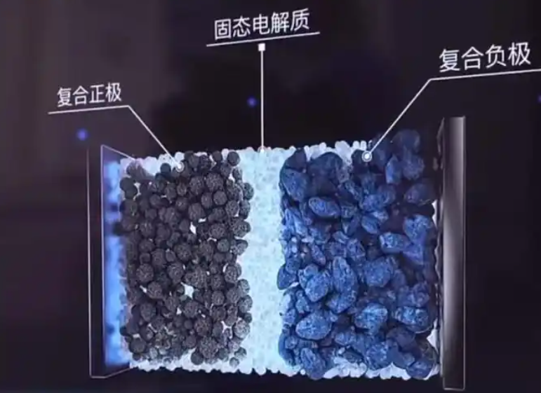
I approached the solid electrolyte cell as an electrochemical system in which the anode interface must simultaneously conduct lithium ions, block excessive electron flow, and distribute current uniformly. In conventional sulfide-based solid electrolyte cells, the interface between Li6PS5Cl and lithium metal is chemically and mechanically heterogeneous. The solid electrolyte has high bulk ionic conductivity, but its grain boundaries, pores, and contact imperfections create local current constrictions. I found that inserting a mixed conductive layer between the electrolyte and the lithium metal changes the boundary conditions of the solid electrolyte cell. Instead of forcing all lithium deposition to occur at a narrow electrolyte–metal contact, the MIEC spreads the deposition reaction over a controlled volume. This volume has both ionic and electronic pathways, so lithium ions and electrons can meet in a distributed manner rather than at isolated hot spots.
Design Logic for the Mixed Conductive Interphase
I based the design on a simple transport argument. In a solid electrolyte cell, the local electrochemical reaction rate depends on the product of ionic availability, electronic availability, and interfacial potential. If only ionic conduction exists at the interface, electrons must arrive through the lithium metal or through conductive additives, which can cause localized plating. If only electronic conduction exists, the interphase behaves like a porous current collector without a lithium-ion supply, and lithium deposition becomes spatially uncontrolled. My intention was therefore to create an intermediate composition in which the electronic conductivity is high enough to reduce charge-transfer resistance but low enough to avoid massive lithium plating inside the interphase.
I represented the total conductivity of the interphase as:
$$ \sigma_{\mathrm{total}} = \sigma_{\mathrm{ion}} + \sigma_{\mathrm{el}} $$
I measured ionic conductivity using:
$$ \sigma_{\mathrm{ion}} = \frac{L}{R_{\mathrm{ion}} A} $$
I measured electronic conductivity using:
$$ \sigma_{\mathrm{el}} = \frac{L}{R_{\mathrm{el}} A} = \frac{I L}{V A} $$
In these expressions, \(L\) is the thickness of the sample or interphase, \(A\) is the cross-sectional area, \(R_{\mathrm{ion}}\) is the ionic resistance, \(R_{\mathrm{el}}\) is the electronic resistance, \(I\) is the applied current, and \(V\) is the measured voltage. I used these equations to quantify the balance between ionic and electronic transport in the solid electrolyte cell. The optimal interphase should not maximize electronic conductivity, because excessive electronic conductivity can accelerate lithium deposition inside the interphase and create irreversible dead lithium. Instead, I sought a composition that provides a mild electronic percolation network while preserving the continuous lithium-ion pathways of the sulfide electrolyte.
I also considered the current distribution within the solid electrolyte cell. In a mixed conductor, the local current density can be written as:
$$ i_{\mathrm{loc}} = -\sigma_{\mathrm{ion}} \nabla \phi_{\mathrm{ion}} – \sigma_{\mathrm{el}} \nabla \phi_{\mathrm{el}} $$
The interfacial overpotential is related to the difference between the electronic and ionic potentials:
$$ \eta_{\mathrm{int}} = \phi_{\mathrm{el}} – \phi_{\mathrm{ion}} – U_{\mathrm{eq}} $$
If the electronic conductivity is too low, \( \phi_{\mathrm{el}} \) cannot adjust rapidly, and lithium deposition becomes concentrated. If the electronic conductivity is too high, \( \eta_{\mathrm{int}} \) is small over a large region, and lithium can plate throughout the interphase. The solid electrolyte cell therefore benefits from an intermediate electronic conductivity. My experiments showed that 1 wt.% Super P was close to this intermediate regime.
Another useful concept for dendrite growth is the Sand-type time scale, which I used as a qualitative guide:
$$ \tau_s \propto \frac{D C_0^2}{j^2} $$
Here, \(D\) is an effective lithium diffusion coefficient, \(C_0\) is the initial lithium concentration, and \(j\) is the applied current density. This relation implies that higher current density accelerates depletion and dendrite initiation. In a solid electrolyte cell, the effective diffusion length and the local current distribution are strongly affected by the interphase. By spreading the current, the MIEC increases the effective area over which lithium is deposited and delays the onset of depletion. This is one reason I observed a higher critical current density in the modified solid electrolyte cell.
Materials and Experimental Framework
I prepared composite interphase materials by manually grinding Li6PS5Cl powder with Super P in an agate mortar. I used mass ratios of 100:0.5, 100:1, and 100:3 for Li6PS5Cl to Super P. I labeled the samples 0.5%SP, 1%SP, and 3%SP according to the Super P mass fraction. I also used pristine Li6PS5Cl as the baseline. The grinding time was 30 min for each mixture to obtain a homogeneous distribution without inducing a chemical reaction. I then assembled symmetric solid electrolyte cells and full solid electrolyte cells under uniaxial pressure. For the symmetric solid electrolyte cell, I first pressed Li6PS5Cl powder at 300 MPa for 1 min, then added the composite interphase on both sides and pressed at 500 MPa for 2 min, and finally attached lithium foil at about 10 MPa. For the full solid electrolyte cell, I used LiNi0.89Co0.06Mn0.05O2 as the cathode active material, mixed with Li6PS5Cl and Super P in a 70:27:3 mass ratio, and assembled the cathode composite, electrolyte layer, interphase, and lithium anode in a die.
| Sample | Li6PS5Cl mass ratio | Super P mass ratio | Super P mass fraction | Intended role in solid electrolyte cell |
|---|---|---|---|---|
| LPSCl | 100 | 0 | 0 wt.% | Baseline sulfide solid electrolyte cell |
| 0.5%SP | 100 | 0.5 | 0.5 wt.% | Low electronic percolation interphase |
| 1%SP | 100 | 1 | 1 wt.% | Optimized mixed conductive interphase |
| 3%SP | 100 | 3 | 3 wt.% | Excessive electronic conduction interphase |
I used X-ray diffraction to examine phase stability, scanning electron microscopy with energy-dispersive X-ray spectroscopy to examine morphology and elemental distribution, X-ray photoelectron spectroscopy to examine chemical states before and after cycling, electrochemical impedance spectroscopy to examine interfacial resistance, and distribution of relaxation times analysis to separate overlapping electrochemical processes. I also performed galvanostatic cycling of symmetric solid electrolyte cells and full solid electrolyte cells at room temperature. I activated full solid electrolyte cells at 0.1C between 2.5 and 4.3 V versus Li+/Li for three cycles before rate and long-term tests.
Structural and Chemical Characterization
I first verified that mechanical mixing did not destroy the sulfide electrolyte structure. The X-ray diffraction patterns of the composite interphase materials retained the characteristic peaks of Li6PS5Cl. I observed the main reflections at approximately 25.7°, 30.2°, and 31.5°, and these positions matched the pristine Li6PS5Cl pattern. I did not detect additional peaks that could be assigned to Super P or to reaction products. This indicated that the sulfide solid electrolyte and Super P were chemically compatible during preparation. The preservation of the Li6PS5Cl framework is important for the solid electrolyte cell because the ionic conduction pathway must remain intact. If the grinding process had decomposed the electrolyte or produced insulating phases, the ionic conductivity would have dropped and the solid electrolyte cell would have suffered from high impedance.
I also examined the cross-section of the 1%SP interphase by scanning electron microscopy. The interphase appeared as a dense composite layer with intimate contact to the adjacent solid electrolyte. The elemental maps showed that carbon, phosphorus, and sulfur were distributed uniformly across the interphase. I did not observe large carbon-rich agglomerates or sulfur-rich domains. This uniform distribution supports the formation of a continuous mixed conductive network. In the solid electrolyte cell, a uniform interphase is essential because any local accumulation of electronic conductor can create a local plating site, while any electronic-insulating region can create a local ionic constriction. The 1%SP composition provided a balanced distribution that was neither too dilute nor too concentrated.
| Characterization method | Information obtained | Observation for 1%SP interphase | Implication for solid electrolyte cell |
|---|---|---|---|
| X-ray diffraction | Phase identity and crystallinity | Li6PS5Cl peaks retained; no new phases | Preserved ionic framework |
| Scanning electron microscopy | Morphology and contact quality | Dense, uniform interphase | Improved interfacial contact |
| Energy-dispersive X-ray spectroscopy | Elemental distribution | Uniform C, P, and S distribution | Continuous mixed conductive network |
| X-ray photoelectron spectroscopy | Chemical states before and after cycling | PS4^3− and P–S–P states retained | Chemical stability of interphase |
Ionic and Electronic Transport
I measured the impedance of the pristine Li6PS5Cl and composite interphases to determine how Super P affects ionic and electronic transport. In the Nyquist plots, the pristine Li6PS5Cl and the 0.5%SP and 1%SP composites showed similar grain-boundary responses. This indicated that low Super P contents did not significantly block lithium-ion transport. I inferred that the sulfide electrolyte particles remained in contact and that the ionic conduction network was preserved. When I increased the Super P content to 3%, however, a clear semicircle appeared in the impedance spectrum. This additional semicircle indicated a substantial increase in interfacial resistance and a degradation of ionic percolation. The excess carbon likely interrupted electrolyte–electrolyte contacts and created insulating gaps within the solid electrolyte cell.
I then measured the electronic conductivity of each composition. The electronic conductivity increased with Super P content, as expected for a percolating carbon network. The values I obtained are summarized below.
| Sample | Electronic conductivity / S cm−1 | Order of magnitude | Effect on solid electrolyte cell |
|---|---|---|---|
| LPSCl | 9.7 × 10⁻¹⁰ | 10−10 | Nearly insulating; localized plating |
| 0.5%SP | 8.25 × 10⁻⁹ | 10−9 | Slightly improved current spreading |
| 1%SP | 1.8 × 10⁻⁸ | 10−8 | Optimal mixed conduction |
| 3%SP | 2.4 × 10⁻⁵ | 10−5 | Excessive plating inside interphase |
The 1%SP interphase gave an electronic conductivity of 1.8 × 10⁻⁸ S cm−1, which was about two orders of magnitude higher than that of the pristine solid electrolyte but still far below the ionic conductivity of Li6PS5Cl. I considered this to be a favorable window for the solid electrolyte cell. The electronic conductivity was high enough to reduce charge-transfer resistance and to distribute electrons over the interphase surface, but not so high that lithium would plate deeply inside the interphase. The 3%SP sample had an electronic conductivity of 2.4 × 10⁻⁵ S cm−1, which was too high. In that case, lithium ions and electrons could combine throughout the interphase, leading to internal deposition, dead lithium, and loss of ionic contact. The solid electrolyte cell with 3%SP therefore showed degraded performance despite its higher electronic conductivity.
I also expressed the transport balance as a dimensionless ratio:
$$ \Lambda = \frac{\sigma_{\mathrm{el}}}{\sigma_{\mathrm{ion}}} $$
For a stable solid electrolyte cell, \( \Lambda \) should be small but nonzero. If \( \Lambda \to 0 \), the interphase behaves as an ionic conductor with no electronic spreading. If \( \Lambda \gg 1 \), the interphase behaves as an electronic conductor with insufficient ionic control. My results suggested that the 1%SP interphase provided an intermediate \( \Lambda \) that promoted uniform lithium deposition without internal short circuits.
Critical Current Density in Symmetric Solid Electrolyte Cells
I evaluated the critical current density of symmetric solid electrolyte cells to determine how much current the interphase could sustain before short circuit. I defined the critical current density as:
$$ j_{\mathrm{CCD}} = \max \left\{ j \mid V(t) \leq V_{\mathrm{cut}} \ \forall t \in [0, t_{\mathrm{test}}] \right\} $$
In this definition, \(j\) is the applied current density, \(V(t)\) is the cell voltage, \(V_{\mathrm{cut}}\) is a voltage threshold, and \(t_{\mathrm{test}}\) is the duration of each current step. I increased the current stepwise and monitored the voltage response. The pristine Li6PS5Cl solid electrolyte cell shorted at a relatively low current density. The 0.5%SP interphase improved the critical current density to 1.1 mA cm−2. The 1%SP interphase increased it further to 1.6 mA cm−2. This was a significant improvement for the solid electrolyte cell because it indicated that the interface could tolerate higher lithium flux before dendrite penetration. In contrast, the 3%SP interphase reduced the critical current density to 0.9 mA cm−2. The excessive electronic conductivity caused lithium to deposit inside the interphase, which created local mechanical stress and accelerated failure.
| Interphase composition | Critical current density / mA cm−2 | Qualitative behavior in solid electrolyte cell |
|---|---|---|
| LPSCl baseline | Below 1.1 | Early short circuit and unstable voltage |
| 0.5%SP | 1.1 | Moderate improvement |
| 1%SP | 1.6 | Best current tolerance and stable voltage |
| 3%SP | 0.9 | Internal plating and premature failure |
I attributed the improved critical current density of the 1%SP solid electrolyte cell to two effects. First, the mixed conductive interphase reduced the local current density at the electrolyte–lithium boundary. Second, the interphase provided a more uniform lithium-ion concentration field. I represented the lithium transport in the interphase as:
$$ \frac{\partial c_{\mathrm{Li}^+}}{\partial t} = D_{\mathrm{Li}^+} \nabla^2 c_{\mathrm{Li}^+} – \frac{\nabla \cdot i_{\mathrm{ion}}}{F} $$
Here, \(c_{\mathrm{Li}^+}\) is the lithium-ion concentration, \(D_{\mathrm{Li}^+}\) is the effective diffusion coefficient, \(i_{\mathrm{ion}}\) is the ionic current density, and \(F\) is the Faraday constant. When the interphase spreads the ionic current, the divergence term becomes less localized, so concentration gradients are reduced. This delays lithium depletion and suppresses dendrite nucleation. My impedance and cycling data were consistent with this interpretation.
In Situ Impedance and Distribution of Relaxation Times
I used in situ electrochemical impedance spectroscopy and distribution of relaxation times analysis to resolve the individual contributions to the total impedance of the solid electrolyte cell. The distribution of relaxation times method transforms the impedance spectrum into a function of relaxation time:
$$ Z(\omega) = R_\infty + \int_{0}^{\infty} \frac{\gamma(\ln \tau)}{1 + j \omega \tau} \, d\ln \tau $$
In this expression, \(Z(\omega)\) is the measured impedance, \(R_\infty\) is the high-frequency resistance, \(\gamma(\ln \tau)\) is the distribution function, \(\tau\) is the relaxation time, and \(\omega\) is the angular frequency. The peak position in the distribution is related to the characteristic frequency by:
$$ \tau = \frac{1}{2\pi f_{\mathrm{peak}}} $$
I assigned the peaks to physical processes according to their time scales. The fastest process, around 1 × 10⁻⁷ to 1 × 10⁻⁵ s, corresponded to grain-boundary impedance in the solid electrolyte and interphase. The intermediate processes, around 1 × 10⁻⁵ to 1 × 10⁻³ s and 1 × 10⁻³ to 1 × 10⁻¹ s, corresponded to the solid electrolyte interphase and charge-transfer resistance at the lithium–electrolyte interface. The slowest process, around 1 × 10⁻¹ to 10 s, corresponded to diffusion in the composite electrode or interphase.
| Relaxation time range / s | Assigned process | Physical meaning in solid electrolyte cell |
|---|---|---|
| 1 × 10⁻⁷ to 1 × 10⁻⁵ | Grain-boundary response | Ion transport across particle–particle contacts |
| 1 × 10⁻⁵ to 1 × 10⁻³ | Interphase and solid electrolyte interphase response | Interfacial film resistance and contact quality |
| 1 × 10⁻³ to 1 × 10⁻¹ | Charge-transfer response | Lithium plating and stripping kinetics |
| 1 × 10⁻¹ to 10 | Diffusion response | Lithium transport in the interphase and electrode |
Before cycling, the distribution of relaxation times peaks for the 1%SP solid electrolyte cell were smaller than those of the pristine Li6PS5Cl solid electrolyte cell in the interphase and charge-transfer regions. This indicated that the mixed conductive interphase improved interfacial contact and reduced the resistance associated with lithium-ion transfer. The grain-boundary peak remained similar, which confirmed that the bulk ionic transport of the sulfide electrolyte was not degraded. After in situ charge and discharge at 0.1 mA cm−2, I observed that the pristine Li6PS5Cl solid electrolyte cell developed a larger grain-boundary peak. This suggested that cycling caused structural degradation at the grain boundaries or at the interface. In contrast, the 1%SP solid electrolyte cell maintained a low grain-boundary resistance and showed reduced charge-transfer resistance. I concluded that the interphase protected the solid electrolyte from degradation and preserved the lithium-ion transport pathways during cycling.
I also used the impedance data to fit an equivalent circuit model:
$$ R_{\mathrm{total}} = R_{\mathrm{bulk}} + R_{\mathrm{gb}} + R_{\mathrm{SEI}} + R_{\mathrm{ct}} + R_{\mathrm{diff}} $$
Here, \(R_{\mathrm{bulk}}\) is the bulk resistance, \(R_{\mathrm{gb}}\) is the grain-boundary resistance, \(R_{\mathrm{SEI}}\) is the interphase resistance, \(R_{\mathrm{ct}}\) is the charge-transfer resistance, and \(R_{\mathrm{diff}}\) is the diffusion-related resistance. The 1%SP solid electrolyte cell showed the lowest sum of \(R_{\mathrm{SEI}}\), \(R_{\mathrm{ct}}\), and \(R_{\mathrm{diff}}\) among the tested compositions. This quantitative result supported my mechanistic picture: the mixed conductive interphase reduces the interfacial barrier and distributes the lithium flux, which improves the kinetics of the solid electrolyte cell.
Long-Term Lithium Plating and Stripping in Symmetric Solid Electrolyte Cells
I tested symmetric solid electrolyte cells under constant current to evaluate long-term stability. The pristine Li6PS5Cl solid electrolyte cell shorted after only 170 h at 0.5 mA cm−2. The voltage suddenly dropped, which indicated that lithium dendrites had penetrated the electrolyte and created an internal short circuit. In contrast, the 1%SP solid electrolyte cell cycled for 2800 h at the same current density. Its polarization voltage remained near 25 mV throughout the test. This long cycle life demonstrated that the mixed conductive interphase effectively stabilized lithium plating and stripping in the solid electrolyte cell.
| Symmetric solid electrolyte cell | Current density / mA cm−2 | Cycle life | Polarization voltage | Failure mode |
|---|---|---|---|---|
| Pristine Li6PS5Cl | 0.5 | 170 h | Voltage collapse | Short circuit from dendrite penetration |
| 1%SP interphase | 0.5 | 2800 h | About 25 mV | Stable plating and stripping |
I attributed the improved cycling stability to the uniform current distribution at the interphase. The 1%SP interphase provided a three-dimensional mixed conductive network. Lithium ions could move through the sulfide electrolyte phase, while electrons could move through the carbon network. The two species met at distributed reaction sites rather than at a single contact point. This reduced the local current density and prevented the formation of lithium protrusions that could penetrate the solid electrolyte. In addition, the interphase maintained good mechanical contact with the lithium metal. The soft lithium metal could conform to the interphase, and the interphase could accommodate small volume changes during plating and stripping. This mechanical compatibility is essential for a long-lived solid electrolyte cell.
I also considered the effect of the interphase on the local electric field. In a homogeneous mixed conductor, the steady-state current distribution tends to smooth the electric field. I wrote the conservation equation as:
$$ \nabla \cdot \left( \sigma_{\mathrm{ion}} \nabla \phi_{\mathrm{ion}} \right) = 0 $$
When \( \sigma_{\mathrm{el}} \) is nonzero, electrons can also redistribute the potential. The coupling between ionic and electronic potentials reduces the driving force for localized deposition. My results showed that this coupling was most effective at 1 wt.% Super P. At 0.5 wt.%, the electronic network was insufficient to spread the current. At 3 wt.%, the electronic network was too strong, and lithium deposited inside the interphase rather than at the interphase–lithium boundary.
Full Solid Electrolyte Cell Performance
I assembled full solid electrolyte cells with LiNi0.89Co0.06Mn0.05O2 cathodes and lithium metal anodes to evaluate the practical impact of the interphase. I first compared the first-cycle charge and discharge capacities at 0.1C. The pristine Li6PS5Cl solid electrolyte cell delivered a charge capacity of 216 mAh g−1 and a discharge capacity of 176 mAh g−1, with a first-cycle Coulombic efficiency of 81.69%. The 0.5%SP solid electrolyte cell delivered 225 mAh g−1 charge capacity and 185 mAh g−1 discharge capacity, with a Coulombic efficiency of 82.22%. The 1%SP solid electrolyte cell delivered 243 mAh g−1 charge capacity and 203 mAh g−1 discharge capacity, with a Coulombic efficiency of 83.45%. The 3%SP solid electrolyte cell delivered 213 mAh g−1 charge capacity and 176 mAh g−1 discharge capacity, with a Coulombic efficiency of 82.35%.
| Solid electrolyte cell | Charge capacity / mAh g−1 | Discharge capacity / mAh g−1 | First-cycle Coulombic efficiency / % |
|---|---|---|---|
| LPSCl baseline | 216 | 176 | 81.69 |
| 0.5%SP | 225 | 185 | 82.22 |
| 1%SP | 243 | 203 | 83.45 |
| 3%SP | 213 | 176 | 82.35 |
I calculated the Coulombic efficiency as:
$$ \eta_{\mathrm{Coulomb}} = \frac{Q_{\mathrm{dis}}}{Q_{\mathrm{chg}}} \times 100\% $$
And I calculated the specific capacity as:
$$ Q = \frac{I t}{m_{\mathrm{active}}} $$
Here, \(Q_{\mathrm{dis}}\) is the discharge capacity, \(Q_{\mathrm{chg}}\) is the charge capacity, \(I\) is the current, \(t\) is the time, and \(m_{\mathrm{active}}\) is the mass of active material. The 1%SP solid electrolyte cell gave the highest discharge capacity and the highest first-cycle Coulombic efficiency. I attributed this to the reduced interfacial resistance and the more uniform lithium deposition. The dQ/dV curves also showed sharper and more intense peaks for the 1%SP solid electrolyte cell, which indicated improved electrochemical reversibility and lower polarization. The 3%SP solid electrolyte cell showed lower capacity because the excessive electronic conductivity caused lithium to deposit inside the interphase, creating dead lithium and reducing the amount of cyclable lithium in the solid electrolyte cell.
I then tested the long-term cycling stability of the 1%SP solid electrolyte cell at 1C. The initial discharge capacity was 150 mAh g−1. After 1000 cycles, the capacity retention was 79.7%. After 2000 cycles, the capacity retention was 68.3%. The solid electrolyte cell did not short during the entire test. I calculated capacity retention as:
$$ C_{\mathrm{ret}}(N) = \frac{Q_N}{Q_1} \times 100\% $$
Here, \(Q_N\) is the discharge capacity at cycle \(N\), and \(Q_1\) is the initial discharge capacity. The high retention at 1C demonstrated that the mixed conductive interphase stabilized the solid electrolyte cell under high-rate operation. The ability to cycle 2000 times without short circuit is especially important because dendrite penetration is one of the main failure modes of sulfide-based solid electrolyte cells. My results showed that the interphase delayed and suppressed this failure mode.
| Test condition | Initial discharge capacity / mAh g−1 | Cycle number | Capacity retention / % | Short circuit |
|---|---|---|---|---|
| 1C, 5.18 mg active material | 150 | 1000 | 79.7 | No |
| 1C, 5.18 mg active material | 150 | 2000 | 68.3 | No |
| 0.3C, 20.32 mg active material | Comparable to low loading | 250 | Nearly unchanged | No |
High-Loading Solid Electrolyte Cell Behavior
I increased the cathode active material loading from 5.18 to 20.32 mg to test the interphase under practical high-loading conditions. High loading increases the areal capacity and reduces the relative contribution of the anode interphase to the total cell impedance. It also makes current distribution more difficult. In my test, the 1%SP solid electrolyte cell maintained its first-cycle discharge capacity and cycled at 0.3C for 250 cycles with almost no capacity fade. This result was important because it showed that the mixed conductive interphase was not only effective in thin-film-like cells but also in high-loading solid electrolyte cells. I attributed this to the ability of the interphase to maintain uniform lithium plating even when the cathode demands a larger total current.
I also considered the area-specific resistance of the solid electrolyte cell:
$$ R_{\mathrm{ASR}} = R_{\mathrm{total}} A $$
High-loading cathodes require low area-specific resistance to avoid large polarization. The 1%SP interphase reduced the interfacial component of the area-specific resistance, which allowed the solid electrolyte cell to operate at higher areal capacity without severe voltage loss. The stable cycling at 20.32 mg active material confirmed that the interphase did not introduce a diffusion bottleneck. Instead, it improved the uniformity of the electrochemical reaction.
Post-Cycling Interface and Lithium Morphology
After cycling, I examined the interface between the interphase and the lithium metal by scanning electron microscopy. I observed that lithium deposition occurred primarily at the interphase–lithium boundary. The lithium morphology was dense and uniform, and I did not observe large dendrites penetrating the interphase or the solid electrolyte. This was in sharp contrast to the pristine solid electrolyte cell, where lithium protrusions can grow into the electrolyte and cause short circuits. The interphase appeared to guide lithium deposition laterally, so that the local current density remained below the threshold for dendrite initiation.
I also examined the cross-section of the cycled solid electrolyte cell. The interphase remained in contact with both the lithium metal and the solid electrolyte. I did not observe large voids or delamination at the interface. This mechanical integrity is important because void formation at the lithium–solid electrolyte interface can increase local current density and accelerate dendrite growth. The mixed conductive interphase helped to maintain contact by distributing the lithium flux and reducing the volume changes at any single point.
To directly observe lithium deposition, I assembled a Li|MIEC|Li6PS5Cl|MIEC|Cu half-cell and charged it at 0.5 mA cm−2. The optical image after charging showed a flat and dense lithium layer on the interphase surface. This confirmed that the interphase had good lithiophilicity and that lithium could deposit uniformly across the surface. In a solid electrolyte cell, uniform lithium deposition is a prerequisite for long cycle life. My observation supported the conclusion that the 1%SP interphase promoted uniform lithium plating rather than localized dendrite growth.
X-ray Photoelectron Spectroscopy and Chemical Stability
I used X-ray photoelectron spectroscopy to examine the chemical stability of the interphase before and after cycling. In the S 2p spectrum, I observed peaks at 161.37 and 162.47 eV, which corresponded to the PS4^3− tetrahedral unit of Li6PS5Cl. I also observed peaks at 162.87 and 162.97 eV, which corresponded to P–S–P bonding. In the P 2p spectrum, I observed peaks at 132.87 and 133.97 eV, which were also consistent with the PS4^3− structure. These assignments indicated that the core structural unit of the sulfide electrolyte remained intact during cycling. I did not observe new peaks that could be assigned to sulfur oxides, phosphorus oxides, or other decomposition products.
| Element and orbital | Binding energy / eV | Assignment | Interpretation for solid electrolyte cell |
|---|---|---|---|
| S 2p | 161.37, 162.47 | PS4^3− tetrahedral unit | Preserved sulfide electrolyte framework |
| S 2p | 162.87, 162.97 | P–S–P bonding | Stable chemical connectivity |
| P 2p | 132.87, 133.97 | PS4^3− structure | No phosphorus oxidation |
| Cl 2p | Overlapping Cl− and LiCl signals | LiCl passivation possible | Limited decomposition and passivation |
I noted that the Cl 2p spectrum can contain overlapping signals from Cl− in Li6PS5Cl and from LiCl that may form by limited electrolyte decomposition. Because the binding energies are close, I did not attempt to quantify them separately. However, the formation of a small amount of LiCl can be beneficial because LiCl can passivate the interface and suppress further decomposition. The important point is that the interphase did not show extensive chemical degradation. The X-ray photoelectron spectroscopy results therefore confirmed that the mixed conductive interphase was chemically compatible with lithium metal and with the sulfide solid electrolyte. This chemical stability is essential for a long-lived solid electrolyte cell.
Mechanistic Model of Dendrite Suppression
I developed a mechanistic model to explain how the mixed conductive interphase suppresses lithium dendrites in the solid electrolyte cell. The model has four coupled elements: current spreading, concentration equalization, mechanical contact, and chemical passivation.
First, current spreading occurs because the interphase has both ionic and electronic conductivity. The local current density is not forced through a single contact point. Instead, the interphase provides a distributed reaction zone. I expressed this as:
$$ i_{\mathrm{loc}} = -\sigma_{\mathrm{ion}} \nabla \phi_{\mathrm{ion}} – \sigma_{\mathrm{el}} \nabla \phi_{\mathrm{el}} $$
When \( \sigma_{\mathrm{el}} \) is moderate, electrons can reach a larger area of the interphase, while \( \sigma_{\mathrm{ion}} \) still supplies lithium ions. The reaction is therefore spread over the interphase surface.
Second, concentration equalization occurs because lithium ions can diffuse laterally within the interphase. The interphase reduces the divergence of ionic current, as described by:
$$ \frac{\partial c_{\mathrm{Li}^+}}{\partial t} = D_{\mathrm{Li}^+} \nabla^2 c_{\mathrm{Li}^+} – \frac{\nabla \cdot i_{\mathrm{ion}}}{F} $$
A smaller divergence term means a smaller concentration gradient. Since dendrite nucleation is often triggered by local lithium depletion or by local accumulation of electric field, a smaller concentration gradient delays nucleation.
Third, mechanical contact is maintained because the interphase is compliant and mixed conductive. The interphase can deform slightly during lithium plating and stripping, and it maintains contact with the lithium metal. This reduces the formation of voids, which are known to concentrate current and accelerate dendrite growth. In my cross-sectional images, the interphase remained attached to the lithium metal after cycling.
Fourth, chemical passivation occurs because the interphase limits direct contact between the highly reactive lithium metal and the sulfide electrolyte. If some decomposition occurs, it forms a thin passivation layer that can suppress further reaction. My X-ray photoelectron spectroscopy results showed that the bulk chemical structure of the sulfide electrolyte remained stable. This means that the interphase served as a chemical buffer in the solid electrolyte cell.
| Mechanistic factor | Role of 1%SP interphase | Consequence for solid electrolyte cell |
|---|---|---|
| Current spreading | Moderate electronic percolation | Lower local current density |
| Concentration equalization | Three-dimensional ion transport | Reduced lithium depletion |
| Mechanical contact | Compliant mixed conductive layer | Fewer voids and delamination |
| Chemical passivation | Limited interfacial decomposition | Preserved sulfide electrolyte |
I also considered the failure mode of the 3%SP solid electrolyte cell. The electronic conductivity was too high, so lithium deposition occurred inside the interphase. This internal deposition reduced the ionic contact and created isolated lithium. The dead lithium increased the impedance and reduced the capacity of the solid electrolyte cell. This observation supports the conclusion that electronic conductivity must be optimized rather than maximized. In my study, 1 wt.% Super P was the optimal composition because it provided enough electronic conductivity for current spreading but not enough to cause internal plating.
Comparison with Other Interfacial Strategies
I compared my mixed conductive interphase strategy with other common approaches for stabilizing the lithium–solid electrolyte interface. One approach is to modify the lithium metal surface with an alloy layer. Another approach is to dope the solid electrolyte to form an in situ passivation layer. A third approach is to use a three-dimensional current collector. Each approach has advantages and limitations. My strategy is distinct because it focuses on the ionic and electronic transport balance at the interface. I do not rely on a single chemical reaction or a single material transformation. Instead, I create a composite layer that controls the local electrochemical environment. This makes the approach versatile for different sulfide solid electrolyte cells.
| Strategy | Main mechanism | Potential limitation | Solid electrolyte cell benefit |
|---|---|---|---|
| Alloy interlayer | Lithiophilic alloy formation | Consumption of lithium and limited thickness control | Improved wetting and nucleation |
| Elemental doping | In situ passivation layer | Bulk electrolyte properties may change | Suppressed interfacial decomposition |
| Three-dimensional current collector | Increased surface area | Complex processing and high porosity | Reduced local current density |
| Mixed conductive interphase | Balanced ion and electron transport | Requires precise composition control | Uniform lithium deposition and dendrite suppression |
I believe the mixed conductive interphase is particularly attractive for solid electrolyte cells because it addresses the root cause of dendrite growth: nonuniform current and ion distribution. If the current is uniform, the electric field is uniform, and lithium deposits uniformly. My impedance and distribution of relaxation times results showed that the interphase reduced the interfacial resistance and improved charge-transfer kinetics. My cycling results showed that the solid electrolyte cell could operate for thousands of hours and thousands of cycles without short circuit. This combination of high performance and mechanistic clarity makes the approach promising for practical solid electrolyte cells.
Practical Implications for Solid Electrolyte Cells
I see several practical implications from my work. First, the interphase can be prepared by simple mechanical mixing and cold pressing, which is compatible with scalable solid electrolyte cell manufacturing. I did not use complex synthesis or high-temperature processing. The Super P additive is commercially available and inexpensive. The Li6PS5Cl electrolyte can be used as received. This simplifies the fabrication of the solid electrolyte cell.
Second, the interphase thickness and composition can be adjusted independently of the bulk electrolyte. This means that the bulk electrolyte can be optimized for ionic conductivity and mechanical strength, while the interphase is optimized for interfacial stability. This decoupling is valuable because the requirements for the bulk and the interface are different. In a solid electrolyte cell, the bulk must conduct lithium ions efficiently, while the interface must distribute current and prevent dendrites. My mixed conductive interphase provides a design tool for this decoupling.
Third, the interphase can be applied to both the anode and the cathode sides if needed. In my study, I focused on the anode side because lithium dendrites are the primary failure mode. However, the same concept could be used to improve cathode–solid electrolyte contact. A mixed conductive interphase on the cathode side could reduce charge-transfer resistance and accommodate volume changes. This suggests a broader design principle for solid electrolyte cells: use mixed conductive interphases to manage heterogeneous interfaces.
Fourth, my results highlight the importance of electronic conductivity in the interphase. Many interfacial coatings are designed to be purely ionic conductors. My work shows that a small amount of electronic conductivity can be beneficial. The key is to avoid excessive electronic conductivity. I quantified this window using the ratio \( \Lambda = \sigma_{\mathrm{el}} / \sigma_{\mathrm{ion}} \). For Li6PS5Cl, the optimal interphase had an electronic conductivity of 1.8 × 10⁻⁸ S cm−1, which was high enough to spread current but low enough to avoid internal plating. This value can serve as a starting point for other sulfide solid electrolyte cells.
Fifth, my long-term cycling data showed that the solid electrolyte cell can be stable for 2800 h at 0.5 mA cm−2 and for 2000 cycles at 1C. These are demanding conditions for a sulfide-based solid electrolyte cell. The fact that the cell did not short indicates that the interphase effectively suppressed dendrite penetration. This is a critical step toward practical solid electrolyte cells with high energy density and high safety.
Limitations and Future Work
I also recognize the limitations of my study. The interphase composition was optimized for Li6PS5Cl and Super P. Other sulfide electrolytes may require different electronic conductivity windows. The mechanical properties of the interphase could be further optimized by using different carbon morphologies or by adding binders. The long-term compatibility with high-voltage cathodes and with lithium metal under high areal capacity also needs further study. In addition, the solid electrolyte cell was tested at room temperature and at moderate stack pressure. Practical cells may operate under different pressures and temperatures.
For future work, I plan to investigate the following directions. I will vary the carbon morphology and surface chemistry to improve the uniformity of the electronic network. I will test the interphase with different sulfide electrolytes and with different lithium alloys. I will use operando imaging to observe lithium deposition in real time. I will also develop a physics-based model that couples ionic transport, electronic transport, and mechanical deformation in the solid electrolyte cell. Such a model could predict the optimal interphase properties for different operating conditions and accelerate the design of solid electrolyte cells.
Conclusion
I demonstrated that a mixed ion–electron conductive interphase between Li6PS5Cl and lithium metal substantially improves the stability of a solid electrolyte cell. The 1 wt.% Super P composition provided the best balance of ionic and electronic transport. Its electronic conductivity was 1.8 × 10⁻⁸ S cm−1, which was high enough to spread current and low enough to avoid internal lithium plating. The interphase increased the critical current density to 1.6 mA cm−2 and enabled a symmetric solid electrolyte cell to cycle for 2800 h at 0.5 mA cm−2 with a polarization voltage of about 25 mV. In full solid electrolyte cells, the 1%SP interphase delivered a discharge capacity of 203 mAh g−1 at 0.1C and retained 79.7% of its capacity after 1000 cycles at 1C. It also supported high-loading cathodes with 20.32 mg active material, cycling for 250 cycles at 0.3C with almost no fade. Structural and chemical characterization confirmed that the interphase preserved the sulfide electrolyte framework and maintained uniform elemental distribution. Post-cycling microscopy showed dense and uniform lithium deposition without dendrite penetration. In situ impedance and distribution of relaxation times analysis showed reduced grain-boundary, interphase, and charge-transfer resistance. I conclude that the mixed conductive interphase works by spreading current, equalizing lithium concentration, maintaining mechanical contact, and providing chemical passivation. This strategy offers a practical and effective route to stable solid electrolyte cells with high energy density, long cycle life, and improved safety.