
I view the solid state battery as one of the most consequential electrochemical architectures for a low-carbon energy system, because it replaces a flammable liquid electrolyte with a solid electrolyte and therefore changes both the safety envelope and the achievable energy density. In my analysis, the solid state battery is not simply a drop-in replacement for a conventional lithium-ion cell. The solid state battery is a coupled mechanical, chemical, electrochemical, and transport system in which the solid-solid interface becomes the controlling element. When I examine the performance limits of a solid state battery, I therefore begin with the interface rather than with the bulk electrolyte alone. The interface determines whether ions cross from one phase to another, whether electrons leak through parasitic paths, whether lithium deposits uniformly, and whether the structure survives repeated volume changes. For this reason, I treat the solid state battery interface as a multiscale design object.
The central problem is that a solid state battery cannot rely on liquid wetting to maintain contact. In a liquid electrolyte cell, the electrolyte can conform to rough electrode surfaces and maintain a large effective contact area. In a solid state battery, the contact between the solid electrolyte and the electrode is discrete, rough, and mechanically constrained. I describe this as the contact discontinuity problem. It produces localized current density, nonuniform lithium deposition, void growth, and eventual interfacial failure. The solid state battery therefore requires interface engineering that is far more deliberate than the separator and electrolyte optimization used in liquid systems.
I organize my discussion around five failure modes: limited contact and nonuniform transport, interfacial chemical reactions and high-impedance phase formation, space charge layer effects, mechanical mismatch and structural degradation, and multi-factor coupling. I then discuss engineering strategies: surface coatings, artificial interlayers, in situ adaptive interface regulation, multiscale structural design, and data-driven interface design. Throughout, I use quantitative relations and tables to summarize the mechanisms and control levers.
My Baseline Architecture and Transport Picture. I start from a general solid state battery stack consisting of a lithium metal or high-capacity anode, a solid electrolyte, a composite cathode, and current collectors. The solid state battery interface can be divided into an anode-solid electrolyte interface and a cathode-solid electrolyte interface. Each interface contains contact regions, voids, reaction products, space charge zones, and stress concentration zones. The total overpotential of the solid state battery can be written as a sum of losses:
$$\eta_\mathrm{total} = \eta_\mathrm{ohmic} + \eta_\mathrm{activation} + \eta_\mathrm{concentration} + \eta_\mathrm{mechanical} + \eta_\mathrm{interfacial}.$$
I use this expression because it forces me to distinguish between bulk resistance and interfacial resistance. In many solid state battery systems, the interfacial term is not a small correction. It can dominate the voltage loss at moderate and high current densities. The interfacial impedance can be decomposed as follows:
$$R_\mathrm{int} = R_\mathrm{contact} + R_\mathrm{film} + R_\mathrm{SCL} + R_\mathrm{charge-transfer} + R_\mathrm{mech}.$$
Here, \(R_\mathrm{contact}\) arises from incomplete physical contact, \(R_\mathrm{film}\) arises from reaction products or passivation layers, \(R_\mathrm{SCL}\) arises from space charge redistribution, \(R_\mathrm{charge-transfer}\) arises from the activated ion transfer step, and \(R_\mathrm{mech}\) represents the additional resistance caused by stress-induced contact loss and crack opening. In my view, any credible solid state battery interface model should track these terms separately, because each term responds differently to coatings, pressure, temperature, and cycling.
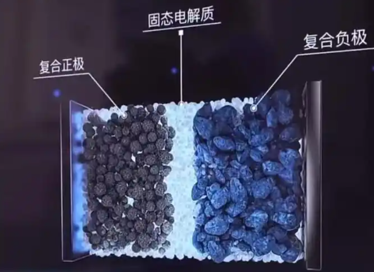
Contact Limitation and Localized Transport. I define the effective contact area fraction as the ratio of true ion-conducting contact area to geometric area:
$$A_\mathrm{eff}/A_\mathrm{geom} = \frac{1}{A_\mathrm{geom}}\int_{A_\mathrm{geom}} \Phi(\mathbf{x})\,dA,$$
where \(\Phi(\mathbf{x})\) is one in contacting regions and zero in voids or insulating regions. For a solid state battery, \(A_\mathrm{eff}/A_\mathrm{geom}\) is often much less than one. This directly increases the local current density:
$$J_\mathrm{loc} = \frac{I}{A_\mathrm{eff}}.$$
The consequence is not merely a higher resistance. The consequence is a spatially nonuniform electrochemical driving force. I therefore treat the solid state battery interface as a current-focusing structure. Local regions with high \(J_\mathrm{loc}\) experience faster lithium deposition, higher local stress, and accelerated reaction product formation. As cycling proceeds, voids expand, contact area decreases, and the solid state battery interface enters a feedback loop of increasing resistance and increasing nonuniformity.
I can express the ion transport problem in the solid electrolyte and at the interface through a coupled Nernst-Planck and Poisson description:
$$J_i = -D_i \nabla c_i – \frac{z_i F D_i c_i}{RT}\nabla \phi,$$
$$\nabla^2 \phi = -\frac{\rho}{\epsilon}.$$
At the solid state battery interface, boundary conditions are not ideal. The contact area may be partial, the reaction rate may be spatially dependent, and the mechanical displacement may open or close pathways. In my framework, the solid state battery interface is therefore a boundary condition problem as much as a materials problem.
Interfacial Chemical Reactions and High-Impedance Layers. I observe that thermodynamic mismatch between the solid electrolyte and the electrode is common in a solid state battery. If the lithium chemical potential in the electrode differs strongly from that in the electrolyte, reduction or oxidation reactions can occur. The driving force can be written as:
$$\Delta G_r = \Delta G_r^0 + RT \ln Q.$$
When \(\Delta G_r\) is negative, the reaction is favorable. In a solid state battery with a sulfide electrolyte and lithium metal, reaction products such as lithium sulfide and phosphorus-containing phases can form. In an oxide electrolyte, lithium-rich oxide interfacial layers can form. These products may be ionically insulating, electronically conducting, or mixed conducting. If they are ionically insulating, they increase \(R_\mathrm{film}\). If they are electronically conducting, they can sustain continuous parasitic reactions. I therefore distinguish between passivating and non-passivating interfacial layers in a solid state battery.
| Failure mechanism | Physical origin | Key relation | Typical signature | Consequence for solid state battery |
|---|---|---|---|---|
| Contact limitation | Roughness, voids, low pressure, modulus mismatch | \(J_\mathrm{loc}=I/A_\mathrm{eff}\) | High frequency semicircle, current constriction | Nonuniform lithium deposition and dendrite initiation |
| Interfacial reaction | Thermodynamic instability, electron leakage | \(\Delta G_r=\Delta G_r^0+RT\ln Q\) | Growing interfacial resistance, new phases | Ion blocking and continued electrolyte consumption |
| Space charge layer | Chemical potential mismatch, charge redistribution | \(L_D=\sqrt{\epsilon RT/(F^2\sum_i z_i^2 c_i)}\) | Extra interfacial resistance, altered activation energy | Reduced ion transfer rate and higher overpotential |
| Mechanical mismatch | Volume change, stiffness contrast, stress concentration | \(\sigma_{ij}=C_{ijkl}(\epsilon_{kl}-\epsilon_{kl}^0)\) | Crack formation, contact loss, pressure sensitivity | Capacity fade and impedance rise |
| Multi-factor coupling | Transport, reaction, stress, and electric field interaction | Coupled PDE system | Accelerated degradation after incubation period | Abrupt failure and poor cycling life |
Space Charge Layer Effects. I also consider the space charge layer in the solid state battery. When the lithium chemical potential differs across the interface, mobile ions redistribute. This creates an electric potential gradient and an additional migration barrier. The Debye length provides a useful length scale:
$$L_D = \sqrt{\frac{\epsilon RT}{F^2 \sum_i z_i^2 c_i}}.$$
If the space charge layer width is comparable to the interface thickness or the Debye length of the solid electrolyte, the effect becomes significant. In a solid state battery with a low-conductivity electrolyte or poor interfacial matching, the space charge layer can become a major bottleneck. I treat it as an electrostatic resistance that adds to the chemical and mechanical resistances.
Mechanical Mismatch and Structural Degradation. I cannot overstate the importance of mechanics in a solid state battery. The solid electrolyte is rigid, while the electrode volume changes during cycling. The volumetric strain is:
$$\epsilon_v = \frac{\Delta V}{3V_0}.$$
The stress state follows Hooke’s law in its tensorial form:
$$\sigma_{ij} = C_{ijkl}(\epsilon_{kl} – \epsilon_{kl}^0).$$
When the electrode expands or contracts against a rigid solid electrolyte, stress concentrates at contact points, edges, and defects. Cracks can initiate and propagate. The energy release rate for a crack of length \(a\) under stress \(\sigma\) can be approximated as:
$$G = \frac{\pi \sigma^2 a}{E’}.$$
If \(G\) exceeds the fracture toughness of the solid electrolyte or the interface, delamination occurs. In my analysis, mechanical degradation is not separate from electrochemical degradation. Crack opening changes the contact area, which changes \(J_\mathrm{loc}\), which changes the reaction rate, which changes the stress field. This coupling is central to solid state battery failure.
Dendrite Growth and Critical Current Density. I consider dendrite growth to be a coupled morphological instability in the solid state battery. A simplified critical current density scaling can be written as:
$$J_\mathrm{crit} \propto \frac{\sigma_\mathrm{frac} \kappa_\mathrm{ion}}{L_\mathrm{defect}},$$
where \(\sigma_\mathrm{frac}\) is a mechanical resistance parameter, \(\kappa_\mathrm{ion}\) is ionic conductivity, and \(L_\mathrm{defect}\) is a characteristic defect length. This expression captures my intuition: a solid state battery with higher ionic conductivity and stronger mechanical suppression can tolerate higher current before dendrites propagate. However, the expression also shows that defects and local contact loss are dangerous, because they reduce the effective length scale and concentrate current.
| Resistance component | Physical meaning | Dependence on pressure | Dependence on temperature | Diagnostic method |
|---|---|---|---|---|
| \(R_\mathrm{contact}\) | Incomplete solid-solid contact | Strongly decreases with pressure until saturation | Weak to moderate | Impedance spectroscopy, contact area imaging |
| \(R_\mathrm{film}\) | Reaction product or passivation layer | Weak unless film fractures | Arrhenius-like | XPS, TEM, impedance growth |
| \(R_\mathrm{SCL}\) | Space charge redistribution | Weak | Moderate | Low-frequency impedance, potential profiling |
| \(R_\mathrm{charge-transfer}\) | Activated ion transfer | Moderate | Strongly decreases with temperature | Exchange current density, symmetric cells |
| \(R_\mathrm{mech}\) | Stress-induced contact loss | Complex, often non-monotonic | Indirect through creep and modulus | Pressure-controlled cycling, acoustic emission |
My Coupled Failure Framework. I summarize the solid state battery interface failure as a set of coupled equations. The electric potential, ionic concentration, stress, and reaction extent evolve together. I can write a compact system:
$$\nabla \cdot (\sigma_\mathrm{ion}\nabla \phi) = 0,$$
$$\frac{\partial c_i}{\partial t} = -\nabla \cdot J_i + R_i,$$
$$\nabla \cdot \sigma = 0,$$
$$\frac{\partial \xi}{\partial t} = k_r f(c_i,\phi,\sigma),$$
where \(\xi\) is the extent of interfacial reaction. This system is not merely mathematical. It reflects my engineering view that a solid state battery cannot be optimized by improving one property in isolation. A coating that blocks electrons but increases stress may fail. A pressure that improves contact but accelerates creep may fail. A highly conductive electrolyte that reacts with lithium may fail. The solid state battery interface is a multi-objective design problem.
| Coupling path | Trigger | Amplifying variable | Observed outcome in solid state battery |
|---|---|---|---|
| Contact to current | Void formation | Local current density | Nonuniform lithium deposition |
| Current to reaction | Local overpotential | Reaction rate | Interfacial film growth |
| Reaction to stress | Volume change of products | Stress concentration | Crack initiation |
| Stress to contact | Crack opening | Contact loss | Impedance rise |
| Contact to dendrite | Defect pathway | Current focusing | Short circuit risk |
Surface Coatings and Interfacial Chemistry Control. I now turn to engineering strategies. The first strategy I consider is surface coating. A nanoscale coating on the electrode or solid electrolyte can create a selective transport layer. Ideally, the coating has high ionic conductivity and low electronic conductivity. I express the selectivity requirement as:
$$\frac{\sigma_\mathrm{ion}}{\sigma_e} \gg 1.$$
If this ratio is large, the coating allows lithium ions to pass while suppressing electron leakage and parasitic reduction. Atomic layer deposition can produce dense and uniform coatings with controlled thickness. Lithium oxynitride coatings can form stable ion-conducting layers. Oxide and fluoride coatings can modify interfacial energy and electronic structure. I have found that coatings are powerful for chemical stabilization, but they do not fully solve contact discontinuity. In a solid state battery, a coating may improve \(R_\mathrm{film}\) and \(R_\mathrm{charge-transfer}\) while leaving \(R_\mathrm{contact}\) largely unchanged.
| Coating family | Primary function | Advantage | Limitation | Solid state battery target |
|---|---|---|---|---|
| Oxide coatings | Block electron transfer | Thermal stability | Can be brittle | Suppress interfacial reduction |
| Fluoride coatings | Modify interfacial energy | Stable against lithium | May have low ionic conductivity | Uniform lithium deposition |
| Lithium oxynitride | Ion-conducting buffer | Good ionic transport | Process complexity | Lower charge-transfer resistance |
| Polymer coatings | Mechanical compliance | Flexible contact | Limited electrochemical window | Buffer volume changes |
| Composite coatings | Mixed ionic and mechanical function | Tunable properties | Difficult scale-up | Balanced interface stability |
Artificial Interlayers and Contact Continuity. I use artificial interlayers when the primary challenge is not only chemistry but also contact. An interlayer can reconstruct the ion transport path and provide mechanical compliance. The ideal interlayer should satisfy several constraints:
$$\sigma_\mathrm{ion}^\mathrm{IL} \ge \sigma_\mathrm{ion}^\mathrm{SE},$$
$$E_\mathrm{IL} \ll E_\mathrm{SE},$$
$$\sigma_e^\mathrm{IL} \ll \sigma_\mathrm{ion}^\mathrm{IL}.$$
Here, \(\sigma_\mathrm{ion}^\mathrm{IL}\) is the ionic conductivity of the interlayer, \(\sigma_\mathrm{ion}^\mathrm{SE}\) is that of the solid electrolyte, \(E_\mathrm{IL}\) is its modulus, and \(E_\mathrm{SE}\) is the modulus of the solid electrolyte. A compliant interlayer can absorb volume changes and maintain contact. A composite interlayer with an alloy phase can reduce the lithium deposition barrier and induce uniform nucleation. A porous or fibrous interlayer can act as a buffer zone. In my assessment, interlayers are among the most adaptable strategies for a solid state battery, but their fabrication complexity is a serious engineering barrier.
| Interlayer design | Main mechanism | Benefit | Risk | Relevant solid state battery interface |
|---|---|---|---|---|
| Alloy-containing interlayer | Lower nucleation barrier | Uniform lithium deposition | Volume expansion | Anode-solid electrolyte |
| Polymer-ceramic hybrid | Ionic conduction plus compliance | Stress buffering | Composite uniformity | Cathode-solid electrolyte |
| Porous buffer layer | Accommodates strain | Contact retention | Density control | High-volume-change electrodes |
| Fibrous interlayer | Continuous ion pathways | Low tortuosity | Manufacturing cost | Composite cathode |
| Gradient interlayer | Smooth chemical and mechanical transition | Reduced stress concentration | Process control | Multimaterial stack |
In Situ Interface Regulation and Adaptive Evolution. I am particularly interested in in situ interface regulation because it allows the solid state battery interface to evolve with cycling. Instead of fixing the interface before operation, I design it to adapt. Mobile species or reactive precursors can migrate to the interface under electric field or chemical potential gradients and form a stable layer. For example, halogen-containing species can enrich at the interface and modify interfacial energy. Polymerizable precursors can cure in situ and fill defects. I describe this as self-healing or adaptive interface behavior.
The benefit is that the solid state battery can maintain interface integrity during repeated cycling. The risk is that the in situ reaction may be difficult to control. If the precursor reacts too quickly, it may form a thick insulating layer. If it reacts too slowly, it may not protect the interface. I therefore treat in situ regulation as a kinetic problem. The Damkohler number is useful:
$$Da = \frac{k_r L^2}{D}.$$
A moderate \(Da\) can allow transport and reaction to balance. A very large \(Da\) leads to reaction-limited interface growth. A very small \(Da\) leads to transport-limited and spatially nonuniform modification. My goal is to tune the solid state battery interface so that the reaction front remains stable and self-limited.
| In situ strategy | Active agent | Trigger | Resulting interface | Challenge |
|---|---|---|---|---|
| Halogen enrichment | Mobile halogen species | Electric field | Stable lithium-rich layer | Uniform distribution |
| Precursor polymerization | Monomer or oligomer | Potential or heat | Dense protective layer | Reaction control |
| Alloy formation | Metal or alloying element | Lithium contact | Lithiophilic interphase | Volume change |
| Self-limiting reaction | Surface species | Chemical potential | Thin stable film | Long-term stability |
| Dynamic repair | Mobile ions | Cycling stress | Defect filling | Kinetic competition |
Multiscale Structural Design. I also use structural design to control the solid state battery interface. A three-dimensional porous electrode increases the effective contact area and reduces local current density. A gradient interface smooths the transition between phases. A multilayer electrolyte can deflect cracks and distribute stress. I express the benefit through a reduced local current density:
$$J_\mathrm{loc} = \frac{I}{A_\mathrm{eff}} \approx \frac{I}{A_\mathrm{geom} f_\mathrm{3D}},$$
where \(f_\mathrm{3D}\) is the geometric contact enhancement factor. When \(f_\mathrm{3D}\) increases, \(J_\mathrm{loc}\) decreases, and the driving force for dendrite formation decreases. In my view, multiscale design is the most direct route to simultaneously improve transport and mechanics in a solid state battery.
| Structural strategy | Length scale | Primary effect | Mechanical effect | Solid state battery benefit |
|---|---|---|---|---|
| Three-dimensional porous electrode | Micro to meso | Higher contact area | Stress distribution | Lower local current density |
| Gradient interface | Nano to micro | Smooth transport transition | Reduced stress concentration | Improved adhesion |
| Multilayer electrolyte | Micro to macro | Crack deflection | Fracture resistance | Longer cycle life |
| Composite cathode | Particle to electrode | Continuous ion paths | Volume change accommodation | Higher areal capacity |
| Patterned interface | Micro | Controlled contact points | Stress redistribution | Suppressed dendrite growth |
Data-Driven Interface Design. I increasingly rely on data-driven methods for solid state battery interface design. The parameter space is too large for purely empirical exploration. A model can map composition and processing variables to properties such as ionic conductivity, electrochemical stability window, and interfacial reaction tendency. I represent the mapping as:
$$\hat{y} = f_\theta(x),$$
where \(x\) contains material and process descriptors, \(\theta\) contains model parameters, and \(\hat{y}\) is the predicted property. The training objective is typically:
$$\mathcal{L}(\theta) = \frac{1}{N}\sum_{i=1}^{N}(y_i – f_\theta(x_i))^2 + \lambda \|\theta\|_2^2.$$
Graph-based models can capture local crystal environments and migration pathways. Machine-learned force fields can accelerate interface reaction simulations. In my framework, data-driven design does not replace physical understanding. It accelerates the search for solid state battery interfaces that satisfy multiple constraints. I can formulate the design problem as a multi-objective optimization:
$$\min_x \left[ R_\mathrm{int}(x), \Delta V(x), C_\mathrm{process}(x), M_\mathrm{risk}(x) \right],$$
subject to stability, conductivity, and manufacturability constraints. Here, \(M_\mathrm{risk}\) represents mechanical failure risk. This formulation captures the practical reality that a solid state battery interface must be good in several dimensions at once.
| Data-driven method | Input | Output | Use for solid state battery | Limitation |
|---|---|---|---|---|
| Regression models | Composition, temperature | Ionic conductivity | Electrolyte screening | Extrapolation risk |
| Graph neural networks | Crystal structure | Migration barrier | Ion transport prediction | Data availability |
| Machine-learned force fields | Atomic configurations | Energy and forces | Interface reaction paths | Training cost |
| Bayesian optimization | Process variables | Optimal recipe | Coating and interlayer design | Experimental noise |
| Generative models | Property targets | Candidate structures | Novel interface materials | Synthesizability |
Electrolyte Families and Interface Matching. I compare solid electrolyte families because the solid state battery interface behavior depends strongly on the electrolyte. Sulfide electrolytes often have high ionic conductivity and good processability, but they can react with lithium metal. Oxide electrolytes have good chemical stability and a wide electrochemical window, but their interfacial contact and processing can be challenging. Polymer electrolytes are flexible and can improve contact, but their ionic conductivity and electrochemical stability may be limited. Halide and composite electrolytes offer tunable properties. I summarize my comparison below.
| Solid electrolyte family | Ionic conductivity | Mechanical behavior | Interface with lithium | Processing | Solid state battery implication |
|---|---|---|---|---|---|
| Sulfide | High | Relatively soft | Reactive | Good | High power but needs protection |
| Oxide | Moderate | Rigid | Stable but contact limited | Difficult | Stable but high interfacial resistance |
| Polymer | Low to moderate | Compliant | Moderate | Easy | Good contact but limited rate |
| Halide | Moderate to high | Tunable | Promising stability | Moderate | Emerging interface control |
| Composite | Tunable | Designable | Depends on phases | Complex | Multifunctional interface |
Thermodynamic and Kinetic Stability Criteria. I use several criteria to screen interface materials for a solid state battery. The electrochemical stability window must include the operating potential of the electrode:
$$E_\mathrm{min} \lt E_\mathrm{electrode} \lt E_\mathrm{max}.$$
The chemical potential difference should not drive continuous decomposition:
$$\Delta \mu_\mathrm{Li} = \mu_\mathrm{Li}^\mathrm{anode} – \mu_\mathrm{Li}^\mathrm{electrolyte}.$$
If \(\Delta \mu_\mathrm{Li}\) is too large, the interface is thermodynamically unstable. However, thermodynamic instability does not always mean failure. If the reaction product is passivating, the solid state battery can still operate. I therefore distinguish between thermodynamic instability and kinetic passivation. The film growth rate can be modeled as:
$$\frac{dL_f}{dt} = k_f \exp\left(-\frac{E_a}{RT}\right) \exp\left(\frac{\alpha F \eta}{RT}\right).$$
This expression shows that temperature and overpotential strongly influence interfacial film growth. In my design process, I aim for a self-limiting film with low electronic conductivity and high ionic conductivity.
| Criterion | Expression | Target for solid state battery | Failure if violated |
|---|---|---|---|
| Electrochemical window | \(E_\mathrm{min} \lt E \lt E_\mathrm{max}\) | Includes anode and cathode potentials | Continuous oxidation or reduction |
| Chemical potential match | \(\Delta \mu_\mathrm{Li}\) small | Reduced driving force | Interfacial decomposition |
| Ionic selectivity | \(\sigma_\mathrm{ion}/\sigma_e \gg 1\) | High ionic, low electronic | Leakage and parasitic reaction |
| Mechanical compliance | \(E_\mathrm{IL} \ll E_\mathrm{SE}\) | Strain accommodation | Cracking and delamination |
| Kinetic passivation | \(dL_f/dt \to 0\) | Self-limited film | Resistance growth |
Pressure, Temperature, and Operating Window. I treat pressure as a design variable in the solid state battery. Pressure improves contact and can suppress void formation, but excessive pressure can fracture particles, accelerate creep, and damage the stack. The optimal pressure is therefore a compromise. I can write a simplified objective for pressure selection:
$$\min_P \left[ R_\mathrm{int}(P) + \lambda_1 \epsilon_\mathrm{frac}(P) + \lambda_2 C_\mathrm{stack}(P) \right].$$
Temperature has a similar dual role. Higher temperature increases ionic conductivity and reaction kinetics, but it also accelerates interfacial reactions and mechanical creep. The ionic conductivity follows an Arrhenius relationship:
$$\sigma_\mathrm{ion} = \frac{A}{T}\exp\left(-\frac{E_a}{k_B T}\right).$$
The effective diffusion coefficient follows a similar form:
$$D_\mathrm{eff} = D_0 \exp\left(-\frac{E_a}{RT}\right).$$
In my view, the operating window of a solid state battery should be defined by the intersection of four constraints: ionic transport, electrochemical stability, mechanical integrity, and thermal safety. A solid state battery that performs well at high temperature but degrades quickly is not a robust engineering solution.
| Operating variable | Positive effect | Negative effect | Design strategy | Solid state battery metric |
|---|---|---|---|---|
| Stack pressure | Improves contact | Fracture and creep | Uniform and controlled pressure | Contact resistance |
| Temperature | Higher conductivity | Faster side reactions | Thermal management | Cycle life |
| Current density | Higher power | Local depletion and dendrites | Rate limiting layers | Critical current density |
| Areal capacity | Higher energy | Larger volume change | Composite electrodes | Capacity retention |
| State of charge | Energy utilization | Stress and chemical potential shifts | Voltage window control | Interface stability |
Diagnostics and Quantification. I rely on multiple diagnostics to separate solid state battery interface failure modes. Electrochemical impedance spectroscopy can identify bulk, grain boundary, and interfacial contributions. The impedance response can be represented as a sum of distributed elements:
$$Z(\omega) = R_\mathrm{bulk} + \sum_k \frac{R_k}{1 + (j\omega\tau_k)^{n_k}} + Z_\mathrm{diff}(\omega).$$
Here, \(\tau_k = R_k C_k\) is a time constant. Constant phase elements are useful because solid state battery interfaces are rarely ideal. Galvanostatic cycling with pressure control can reveal mechanical degradation. Symmetric cells can isolate anode and cathode interfaces. Cross-sectional imaging can reveal void evolution. I combine these methods because no single technique can fully capture the coupled nature of a solid state battery interface.
| Diagnostic | Measured quantity | Interface property | Strength | Limitation |
|---|---|---|---|---|
| Electrochemical impedance spectroscopy | Impedance spectrum | \(R_\mathrm{contact}\), \(R_\mathrm{film}\), \(R_\mathrm{ct}\) | Non-destructive | Overlapping time constants |
| Galvanostatic cycling | Voltage and capacity | Overpotential and degradation | Application relevant | Indirect mechanism |
| Symmetric cells | Anode-anode impedance | Anode interface | Isolates anode effects | Not full cell |
| Cross-sectional microscopy | Voids, cracks, contact | Morphology | Direct observation | Sample preparation |
| Surface spectroscopy | Chemical composition | Reaction products | Chemical specificity | Surface sensitivity |
| Pressure-controlled testing | Force and displacement | Mechanical response | Couples mechanics and electrochemistry | Complex setup |
Scale-Up and Manufacturing Constraints. I recognize that solid state battery interface engineering must survive scale-up. A coating that works at the coin-cell scale may fail in a large pouch cell because pressure distribution, temperature distribution, and current distribution become nonuniform. I express the scale-up challenge through dimensionless groups. The Peclet number compares convection or migration to diffusion:
$$Pe = \frac{u L}{D}.$$
The Fourier number compares diffusion time to process time:
$$Fo = \frac{D t}{L^2}.$$
The dimensionless current can be written as:
$$N = \frac{F L^2}{D c_0}.$$
When these numbers shift during scale-up, the solid state battery interface can transition from uniform to nonuniform behavior. I therefore advocate for interface designs that are robust across a range of pressure, temperature, and current density. Roll-to-roll processing can improve manufacturing efficiency, but it also imposes constraints on coating thickness, interlayer adhesion, and roll pressure. In my assessment, the solid state battery interface must be designed for manufacturability from the beginning, not after cell design.
| Scale-up issue | Micro-cell behavior | Large-cell behavior | Engineering response | Solid state battery consequence |
|---|---|---|---|---|
| Pressure uniformity | Nearly uniform | Nonuniform | Compliant platens and cell design | Local contact loss |
| Current distribution | Uniform | Edge and tab effects | Current collector design | Local lithium deposition |
| Thermal distribution | Isothermal | Hot spots | Thermal management | Accelerated side reactions |
| Coating uniformity | High control | Defects and pinholes | Process metrology | Electronic leakage |
| Stack alignment | Easy | Misalignment risk | Automated assembly | Interfacial stress |
My Integrated Design Matrix. I find it useful to combine failure mechanisms and engineering strategies into a single matrix. This matrix guides my decisions when I design a solid state battery interface. Each strategy targets one or more mechanisms, but every strategy also introduces trade-offs.
| Strategy | Contact limitation | Interfacial reaction | Space charge | Mechanical mismatch | Primary trade-off |
|---|---|---|---|---|---|
| Surface coating | Low impact | High impact | Moderate impact | Low impact | Thickness and brittleness |
| Artificial interlayer | High impact | Moderate impact | Moderate impact | High impact | Process complexity |
| In situ regulation | Moderate impact | High impact | Moderate impact | Moderate impact | Kinetic control |
| Multiscale structure | High impact | Low to moderate | Low impact | High impact | Manufacturing cost |
| Data-driven design | Indirect | Indirect | Indirect | Indirect | Data quality |
Performance Metrics I Would Track. When I evaluate a solid state battery interface, I do not rely on a single metric. I track interfacial resistance, critical current density, capacity retention, Coulombic efficiency, pressure sensitivity, and thermal stability. I summarize these metrics and their meanings below.
| Metric | Definition | Target direction | Dominant failure mode | Interpretation for solid state battery |
|---|---|---|---|---|
| Interfacial resistance | \(R_\mathrm{int}\) | Low and stable | Contact and reaction | Ion transfer efficiency |
| Critical current density | \(J_\mathrm{crit}\) | High | Dendrite and contact | Power capability |
| Capacity retention | \(Q_N/Q_0\) | High after many cycles | Mechanical and chemical | Cycle life |
| Coulombic efficiency | \(Q_\mathrm{dis}/Q_\mathrm{chg}\) | Close to one | Parasitic reactions | Side reaction severity |
| Pressure sensitivity | \(\partial R_\mathrm{int}/\partial P\) | Low | Contact limitation | Stack design freedom |
| Thermal stability | Onset temperature | High | Safety | Intrinsic advantage |
Design Rules I Extract. From the mechanisms and strategies, I extract several design rules for a solid state battery interface. First, I should minimize electronic conductivity at the interface while maintaining high ionic conductivity. Second, I should provide mechanical compliance without sacrificing structural integrity. Third, I should distribute current uniformly to avoid local dendrite nucleation. Fourth, I should design for self-limited reactions rather than complete thermodynamic inertness. Fifth, I should measure and control pressure, temperature, and current distribution at the cell level. Sixth, I should use data-driven methods to explore the multidimensional design space but validate predictions with physical experiments.
I can express the first design rule quantitatively:
$$\sigma_e^\mathrm{int} \ll \sigma_\mathrm{ion}^\mathrm{int}.$$
The second rule can be expressed as a compliance ratio:
$$C_\mathrm{int} = \frac{E_\mathrm{SE}}{E_\mathrm{int}} \gg 1.$$
The third rule can be expressed as a uniformity metric:
$$U_J = 1 – \frac{\max(J_\mathrm{loc}) – \min(J_\mathrm{loc})}{\bar{J}}.$$
I aim for \(U_J\) close to one, meaning uniform current distribution. The fourth rule can be expressed as a self-limiting film condition:
$$\frac{dL_f}{dt} \to 0 \quad \text{as} \quad L_f \to L_\mathrm{stable}.$$
These rules are simple, but they capture the essential trade-offs I see in solid state battery interface engineering.
Failure Evolution Over Time. I think of solid state battery interface failure as a staged process. In the first stage, contact is incomplete but the cell may appear stable. In the second stage, local current concentration drives nonuniform deposition and reaction product growth. In the third stage, mechanical stress opens cracks and voids. In the fourth stage, the interface becomes discontinuous, and impedance rises rapidly. I summarize this progression below.
| Stage | Dominant process | Observable signature | Interface state | Reversible or irreversible |
|---|---|---|---|---|
| Initial | Partial contact | High frequency resistance | Discrete contact | Partially reversible with pressure |
| Early cycling | Current focusing | Increasing overpotential | Local reaction | Partially reversible |
| Intermediate | Film growth and stress | Impedance rise | Mixed contact and film | Mostly irreversible |
| Late | Crack propagation | Capacity fade | Discontinuous interface | Irreversible |
| Failure | Dendrite or delamination | Short circuit or open circuit | Mechanical failure | Catastrophic |
Toward Predictive Interface Engineering. I want solid state battery interface engineering to become predictive rather than empirical. This requires coupling continuum models, atomistic simulations, and machine learning. A multiscale workflow can be written as:
$$\text{atomistic} \rightarrow \text{interface kinetics} \rightarrow \text{continuum transport} \rightarrow \text{cell performance}.$$
At the atomistic scale, I compute migration barriers and reaction energies. At the interface scale, I compute film growth and charge transfer. At the continuum scale, I compute current distribution, stress, and heat. At the cell scale, I predict voltage, capacity, and cycle life. Data flows in both directions: cell-level failures inform which interface mechanisms need further atomistic study. I believe this closed-loop approach is necessary for the solid state battery to move from laboratory promise to reliable product.
| Scale | Model | Key output | Input to next scale | Solid state battery relevance |
|---|---|---|---|---|
| Atomic | DFT, molecular dynamics | Migration barrier, reaction energy | Kinetic parameters | Interface stability |
| Interface | Butler-Volmer, phase field | Charge transfer, film growth | Boundary conditions | Impedance evolution |
| Continuum | Nernst-Planck, Poisson, elasticity | Current, stress, concentration | Effective properties | Local degradation |
| Cell | Pseudo-two-dimensional or 3D model | Voltage, capacity, temperature | Performance prediction | Design validation |
| System | Thermal and pack model | Safety, lifetime | Operating limits | Application integration |
My View on Material Selection. I do not believe there is a single ideal solid state battery interface material. The choice depends on the electrode, the electrolyte, the operating temperature, the current density, and the manufacturing process. For a lithium metal anode, I prioritize a coating or interlayer that is stable against lithium and mechanically compliant. For a high-voltage cathode, I prioritize a coating that suppresses oxidation and prevents oxygen or transition metal diffusion. For a high-power cell, I prioritize low interfacial resistance and high critical current density. For a high-energy cell, I prioritize mechanical stability and areal capacity. I summarize these priorities below.
| Application priority | Anode interface | Cathode interface | Electrolyte requirement | Solid state battery design focus |
|---|---|---|---|---|
| High power | Low \(R_\mathrm{ct}\) | Fast ion transfer | High ionic conductivity | Thin interlayers |
| High energy | Stable lithium plating | High areal capacity | Wide stability window | Mechanical buffer |
| Long life | Self-limiting reaction | Suppressed phase transition | Chemical compatibility | Crack-resistant structure |
| Safety | No dendrite penetration | No oxygen release | Thermal stability | Robust interface |
| Low cost | Scalable coating | Earth-abundant materials | Manufacturable electrolyte | Simple process |
Remaining Gaps I See. I see several unresolved gaps in solid state battery interface research. The first is consistency of interface structure at large scale. A perfect interface in a small cell may not be reproducible in a large cell. The second is matching across multiple materials. A coating that works for one electrolyte may fail for another. The third is long-term stability under dynamic load. Most tests use constant current, but real applications use variable power and temperature. The fourth is the lack of standardized metrics. Different studies report interfacial resistance differently, which makes comparison difficult. The fifth is the challenge of separating coupled mechanisms. When impedance rises, it is often unclear whether contact, reaction, space charge, or mechanics dominates. I believe progress will come from combining in situ diagnostics with physics-based models and data-driven analysis.
I can express the need for standardization with a normalized interface resistance:
$$R_\mathrm{int}^\mathrm{norm} = R_\mathrm{int} A_\mathrm{geom}.$$
Reporting \(R_\mathrm{int}^\mathrm{norm}\) helps compare different cells. I can also define a stability factor:
$$S = \frac{R_\mathrm{int}(N)}{R_\mathrm{int}(0)},$$
where \(N\) is cycle number. A stable solid state battery interface should have \(S\) close to one over its intended life. I would combine \(S\) with capacity retention and critical current density to create a composite score:
$$F_\mathrm{score} = w_1 \frac{1}{R_\mathrm{int}} + w_2 J_\mathrm{crit} + w_3 \frac{Q_N}{Q_0} – w_4 C_\mathrm{process}.$$
Such a score is not a substitute for physical understanding, but it helps rank designs for a solid state battery.
| Gap | Why it matters | Possible approach | Expected benefit for solid state battery |
|---|---|---|---|
| Large-scale uniformity | Small cells overpredict performance | Roll-to-roll metrology and modeling | Reliable manufacturing |
| Multi-material matching | Interfaces are not independent | Combinatorial experiments and ML | Faster material selection |
| Dynamic operation | Real loads vary | Protocols with variable current and temperature | Realistic lifetime prediction |
| Standard metrics | Difficult comparison | Normalized resistance and stability factor | Clear benchmarking |
| Mechanism separation | Coupled failure is ambiguous | In situ diagnostics plus multiphysics models | Targeted engineering |
Engineering Recommendations I Would Give. If I were to translate this analysis into engineering recommendations for a solid state battery, I would emphasize the following. First, design the interface as a functional layer with selective ionic and electronic properties. Second, use a compliant interlayer where mechanical mismatch is severe. Third, use in situ adaptive chemistry where the interface must evolve during cycling. Fourth, use multiscale structures to distribute current and stress. Fifth, use data-driven models to navigate the design space. Sixth, validate every interface design under realistic pressure, temperature, and current profiles. Seventh, treat manufacturing variability as a first-order design constraint. These recommendations are not independent. They form an integrated strategy for solid state battery interface engineering.
I also emphasize that the solid state battery interface is not a passive boundary. It is an active electrochemical region where ion transfer, electron transfer, chemical reaction, and mechanical deformation occur simultaneously. The solid state battery will succeed only if this region is designed with the same rigor as the bulk electrolyte and electrode. In my view, the next generation of solid state battery research should focus on predictive, multi-objective, and scalable interface design.
| Recommendation | Primary target | Quantitative goal | Risk to manage | Solid state battery outcome |
|---|---|---|---|---|
| Selective functional layer | Reaction and leakage | \(\sigma_\mathrm{ion}/\sigma_e \gg 1\) | Thickness and brittleness | Lower parasitic current |
| Compliant interlayer | Mechanical mismatch | \(E_\mathrm{IL} \ll E_\mathrm{SE}\) | Process complexity | Better contact retention |
| In situ adaptive layer | Dynamic defects | Moderate \(Da\) | Kinetic control | Self-repairing interface |
| Multiscale structure | Current and stress distribution | High \(U_J\) | Manufacturing cost | Uniform cycling |
| Data-driven design | Design space exploration | Low prediction error | Data quality | Faster optimization |
| Realistic validation | Application relevance | Stable \(S\) over N cycles | Test time | Reliable lifetime prediction |
Concluding Synthesis. I conclude that the solid state battery interface is the decisive factor in performance, safety, and lifetime. The failure mechanisms are coupled: contact limitation increases local current, local current accelerates interfacial reaction, reaction products increase impedance and stress, stress causes crack and contact loss, and contact loss restarts the cycle. Effective engineering must therefore be multidimensional. Surface coatings control chemistry, artificial interlayers restore contact continuity, in situ regulation enables adaptive evolution, multiscale structures distribute current and stress, and data-driven methods accelerate discovery. I do not see these as competing strategies. I see them as complementary tools that should be combined according to the dominant failure mode of a given solid state battery.
In my final assessment, the solid state battery will not be limited by the intrinsic ionic conductivity of the electrolyte alone. It will be limited by how well the interface can transport ions, block electrons, tolerate strain, and resist chemical degradation over thousands of cycles. The solid state battery interface must be treated as a designed functional system. When I apply this perspective, the path forward becomes clearer: build predictive models, measure the right quantities, design for manufacturability, and integrate chemistry, mechanics, and data. That is the engineering strategy I would pursue for the solid state battery interface.
| Core challenge | Dominant physics | Key control variable | Preferred strategy | Desired solid state battery state |
|---|---|---|---|---|
| Poor contact | Contact mechanics | Pressure, compliance | Interlayer and stack design | Continuous ion paths |
| Side reactions | Thermodynamics and kinetics | Chemical potential, coating | Selective coating | Self-limited interface |
| Space charge | Electrostatics | Doping, potential match | Interface composition tuning | Low migration barrier |
| Mechanical failure | Fracture and creep | Modulus, strain, pressure | Compliant structure | Crack-resistant stack |
| Nonuniform current | Transport and geometry | Effective area, tortuosity | 3D and gradient design | Uniform lithium flux |
| Slow discovery | Large design space | Data and descriptors | Machine learning | Predictable optimization |
I end with a simple statement of my engineering philosophy for the solid state battery: the interface is not a defect to be minimized; it is a functional region to be designed. The solid state battery will achieve its promise when interface chemistry, interface mechanics, interface transport, and interface manufacturing are optimized together. That is the central lesson I draw from the failure mechanisms and the control strategies, and it is the principle I would use to guide the next generation of solid state battery development.