
In my design work, I treat the PMSM electric motor as the central component of a battery electric vehicle drive system. The PMSM electric motor is selected because it offers high power density, high torque density, a wide constant-power speed range, and high efficiency. I begin with the vehicle-level requirements and then move step by step toward the electromagnetic, thermal, and mechanical design of a 25 kW PMSM electric motor. My target is a PMSM electric motor that can deliver strong starting torque, high acceleration, efficient cruising, and reliable flux weakening up to a high peak speed. The design process is not a single calculation. It is an iterative loop in which I adjust the main dimensions, rotor magnetic circuit, permanent magnet size, flux barriers, winding layout, and control assumptions until the calculated performance matches the vehicle requirements.
The key requirements of my PMSM electric motor are listed in Table 1. I use these values as the boundary conditions for all later calculations. The DC bus voltage is 312 V. The rated current is 90 A, and the peak current is 260 A. The rated torque is 80 N·m, and the peak torque is 215 N·m. The rated speed is 3000 r/min, and the peak speed is 8000 r/min. The rated power is 25 kW, and the peak power is 50 kW. The maximum efficiency target is 95%. These values define the operating envelope of the PMSM electric motor and guide the selection of the stator diameter, stator length, rotor topology, permanent magnet dimensions, and winding turns.
Table 1. Main requirements of the PMSM electric motor
| Parameter | Value | Unit |
|---|---|---|
| DC bus voltage | 312 | V |
| Rated current | 90 | A |
| Peak current | 260 | A |
| Rated torque | 80 | N·m |
| Peak torque | 215 | N·m |
| Rated speed | 3000 | r/min |
| Peak speed | 8000 | r/min |
| Rated power | 25 | kW |
| Peak power | 50 | kW |
| Maximum efficiency | 95 | % |
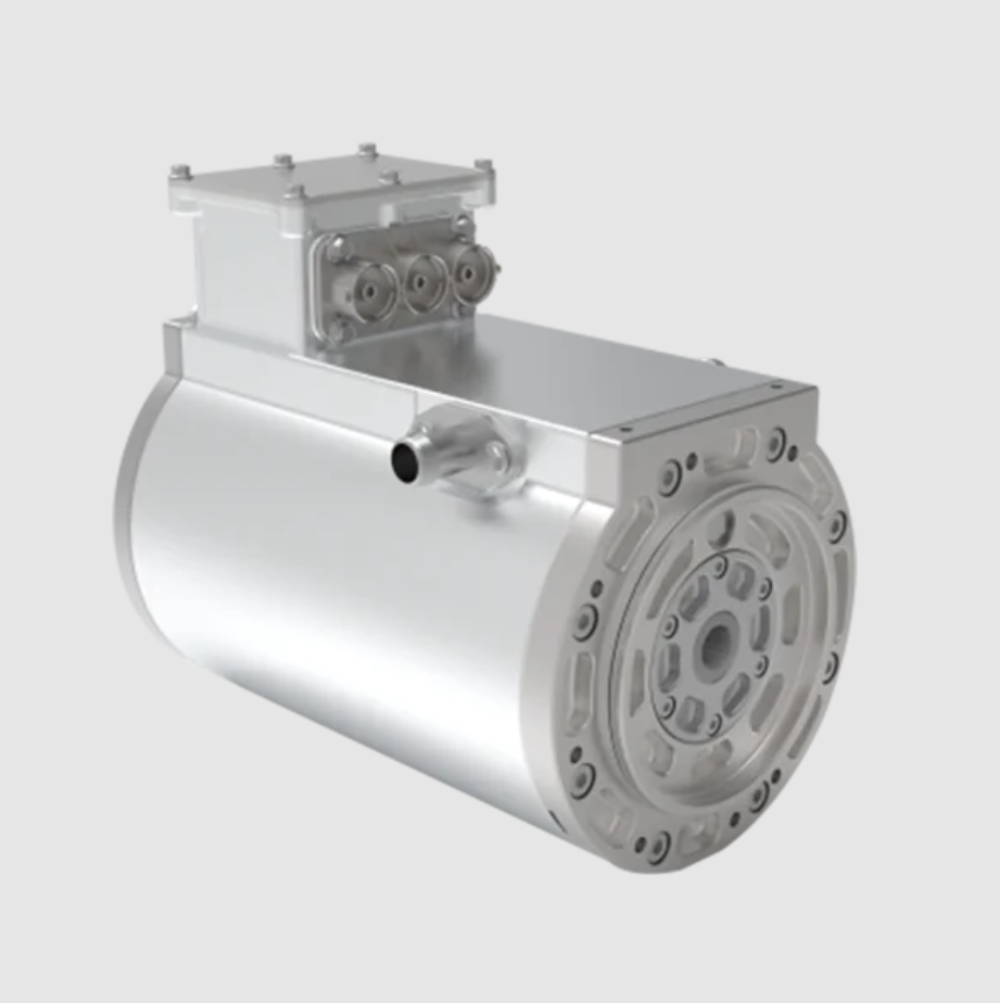
I first establish the overall architecture of the PMSM electric motor. I use a three-phase PMSM electric motor with a Y-connected stator winding and an interior permanent magnet rotor. The interior permanent magnet rotor is preferred because it allows the PMSM electric motor to use both permanent magnet torque and reluctance torque. This combination is important for electric vehicle traction, where the PMSM electric motor must produce a high peak torque for starting and acceleration and still operate efficiently at high speed. The stator is designed with a distributed winding to reduce harmonic content and improve the sinusoidal quality of the back electromotive force. The rotor is designed with multiple magnetic poles and flux barriers to control leakage and improve flux weakening. The following figure shows the general structure of the PMSM electric motor that I use as the basis of my design study.
I use the calculated power relationship to determine the main dimensions of the PMSM electric motor. The calculated power is not identical to the rated shaft power because the PMSM electric motor must satisfy the apparent power requirement of the inverter and the electromagnetic load limits of the machine. For a PMSM electric motor with sinusoidal supply and sinusoidal back electromotive force, I express the calculated power as
$$P’ = \frac{\pi}{2} \alpha A B_\sigma D_{i1}^2 l_{eff} n$$
where \(P’\) is the calculated power, \(\alpha\) is the calculation pole-arc coefficient, \(A\) is the electrical loading, \(B_\sigma\) is the fundamental air-gap flux density amplitude, \(D_{i1}\) is the stator inner diameter, \(l_{eff}\) is the effective axial length, and \(n\) is the speed. The product \(D_{i1}^2 l_{eff}\) is the main size factor of the PMSM electric motor. If I increase this product, the PMSM electric motor can produce more torque, but the volume, mass, and material cost also increase. Therefore, I use this equation together with the vehicle installation space and the target torque to find a balanced main size.
For traction applications, I require the peak torque of the PMSM electric motor to be much larger than the rated torque. I set the ratio between peak torque and rated torque as
$$T_{max} = k_T T_n$$
where \(T_{max}\) is the peak torque, \(T_n\) is the rated torque, and \(k_T\) is the torque overload factor. For my design, \(T_n = 80\) N·m and \(T_{max} = 215\) N·m, which gives
$$k_T = \frac{215}{80} = 2.6875$$
This value is within the desired range of approximately 2.5 to 3.0. The peak torque of the PMSM electric motor is produced by the combined action of permanent magnet flux and reluctance torque. The electromagnetic torque can be written as
$$T_e = \frac{3p}{2} \left[ \psi_f i_q + (L_d – L_q) i_d i_q \right]$$
where \(p\) is the number of pole pairs, \(\psi_f\) is the permanent magnet flux linkage, \(i_d\) and \(i_q\) are the d-axis and q-axis currents, and \(L_d\) and \(L_q\) are the d-axis and q-axis inductances. For an interior permanent magnet PMSM electric motor, \(L_q\) is larger than \(L_d\), so the reluctance term contributes positively when \(i_d\) is negative. This is one of the main reasons I select an interior rotor structure for the PMSM electric motor.
Table 2. Main dimension selection for the PMSM electric motor
| Parameter | Symbol | Value | Unit |
|---|---|---|---|
| Stator inner diameter | \(D_{i1}\) | 125 | mm |
| Effective axial length | \(l_{eff}\) | 110 | mm |
| Air-gap length | \(\delta\) | 0.70 | mm |
| Stator slots | \(Q_s\) | 48 | – |
| Rotor poles | \(2p\) | 8 | – |
| Pole pairs | \(p\) | 4 | – |
| Rated speed | \(n_n\) | 3000 | r/min |
| Peak speed | \(n_{max}\) | 8000 | r/min |
The stator inner diameter and effective axial length are chosen as \(D_{i1} = 125\) mm and \(l_{eff} = 110\) mm. I check the resulting main size factor as
$$D_{i1}^2 l_{eff} = 125^2 \times 110 = 1.71875 \times 10^6 \ \text{mm}^3$$
This value is consistent with the torque and speed requirements of the PMSM electric motor and with the available space inside the vehicle drive unit. I also check the electrical frequency at the rated speed and peak speed. The electrical frequency is
$$f = \frac{p n}{60}$$
At rated speed,
$$f_n = \frac{4 \times 3000}{60} = 200 \ \text{Hz}$$
At peak speed,
$$f_{max} = \frac{4 \times 8000}{60} = 533.33 \ \text{Hz}$$
These frequencies are important for iron loss, inverter switching, and flux-weakening control. I design the PMSM electric motor so that the stator lamination and winding insulation can withstand the high-frequency effects at the peak speed.
I select a 48-slot, 8-pole combination for the PMSM electric motor. The slot number per pole per phase is
$$q = \frac{Q_s}{2p m}$$
where \(m\) is the number of phases. With \(Q_s = 48\), \(2p = 8\), and \(m = 3\),
$$q = \frac{48}{8 \times 3} = 2$$
A fractional-slot distributed winding can reduce torque ripple and harmonic loss, but an integer-slot winding with \(q = 2\) offers a simpler manufacturing process and a robust winding factor. I use a short-pitch double-layer winding to reduce the fifth and seventh harmonics. The slot pitch is
$$\tau_s = \frac{360^\circ}{Q_s} = \frac{360^\circ}{48} = 7.5^\circ$$
The pole pitch in slot number is
$$\tau_p = \frac{Q_s}{2p} = \frac{48}{8} = 6 \ \text{slots}$$
I choose a coil pitch of 5 slots. Therefore, the short-pitch factor is
$$k_{p1} = \sin\left(\frac{\pi}{2} \frac{y}{\tau_p}\right) = \sin\left(\frac{\pi}{2} \frac{5}{6}\right) = \sin(75^\circ) = 0.9659$$
The distribution factor for \(q = 2\) and \(m = 3\) is
$$k_{d1} = \frac{\sin(q \alpha_{slot}/2)}{q \sin(\alpha_{slot}/2)}$$
where
$$\alpha_{slot} = \frac{2\pi p}{Q_s} = \frac{2\pi \times 4}{48} = \frac{\pi}{6} = 30^\circ$$
Thus,
$$k_{d1} = \frac{\sin(2 \times 30^\circ / 2)}{2 \sin(30^\circ / 2)} = \frac{\sin(30^\circ)}{2 \sin(15^\circ)} = \frac{0.5}{2 \times 0.2588} = 0.9659$$
The fundamental winding factor is
$$k_{w1} = k_{d1} k_{p1} = 0.9659 \times 0.9659 = 0.9330$$
This winding factor is high enough to produce a strong fundamental air-gap flux linkage and to reduce the harmonic content of the PMSM electric motor.
Table 3. Slot-pole and winding factors
| Parameter | Symbol | Value |
|---|---|---|
| Stator slots | \(Q_s\) | 48 |
| Rotor poles | \(2p\) | 8 |
| Slots per pole per phase | \(q\) | 2 |
| Coil pitch | \(y\) | 5 slots |
| Pole pitch in slots | \(\tau_p\) | 6 slots |
| Short-pitch factor | \(k_{p1}\) | 0.9659 |
| Distribution factor | \(k_{d1}\) | 0.9659 |
| Winding factor | \(k_{w1}\) | 0.9330 |
After the main dimensions and slot-pole combination, I select the rotor magnetic circuit of the PMSM electric motor. For electric vehicle traction, the PMSM electric motor must produce high torque at low speed and maintain controllability at high speed. This requirement leads me to an interior permanent magnet rotor. In an interior PMSM electric motor, the permanent magnets are buried inside the rotor lamination. This arrangement creates saliency, increases the d-axis inductance, and allows the PMSM electric motor to use reluctance torque. It also protects the permanent magnets from demagnetization and from mechanical damage at high speed. I compare several rotor topologies in Table 4.
Table 4. Rotor topology comparison for the PMSM electric motor
| Rotor type | Reluctance torque | Flux weakening | Mechanical strength | Demagnetization risk |
|---|---|---|---|---|
| Surface-mounted PMSM electric motor | Low | Limited | Moderate | Higher |
| Inset PMSM electric motor | Moderate | Moderate | Moderate | Moderate |
| Interior radial PMSM electric motor | High | Good | High | Low |
| Interior V-shaped PMSM electric motor | High | Very good | High | Low |
I choose the interior radial PMSM electric motor structure. This structure gives me a large d-axis synchronous inductance, which helps flux weakening. It also improves the irreversible demagnetization withstand capability. The reluctance torque is used effectively because the permanent magnet flux linkage can be reduced by appropriate d-axis current control. The mechanical strength of the rotor is high, so the PMSM electric motor can operate at 8000 r/min without excessive stress. For these reasons, the interior radial structure is a mainstream choice for electric vehicle PMSM electric motor designs.
The permanent magnet dimensions are among the most important parameters of the PMSM electric motor. The magnet axial length \(L_M\) is usually equal or close to the stator stack length. Therefore, I focus on the magnet magnetization direction length \(h_M\) and the magnet width \(b_M\). For an interior radial rotor structure, I use the following estimation relationships:
$$b_M = K_\alpha \frac{\sigma_0 B_\sigma \tau_p l_{eff}}{B_r l_M}$$
$$h_M = K_s \frac{\mu_r \delta B_\sigma}{B_r – \sigma_0 B_\sigma}$$
Here, \(K_\alpha\) is a coefficient related to the rotor structure and usually ranges from 0.7 to 1.2. The no-load leakage flux coefficient \(\sigma_0\) for an interior PMSM electric motor is often selected between 1.2 and 1.4. The saturation coefficient \(K_s\) is usually between 1.05 and 1.2. The remanence of the permanent magnet is \(B_r\), the relative permeability is \(\mu_r\), and the air-gap length is \(\delta\). I use a high-performance neodymium-iron-boron material with a grade equivalent to N42OH. This material provides high remanence, high coercivity, and good thermal stability for the PMSM electric motor.
Using my initial electromagnetic loading and rotor dimensions, I estimate the permanent magnet dimensions as
$$b_M \approx 22 \ \text{mm}$$
$$h_M \approx 7.0 \ \text{mm}$$
I then check whether these dimensions provide sufficient flux linkage and sufficient demagnetization margin. The permanent magnet flux linkage can be approximated as
$$\psi_f = N k_w \Phi_f$$
where \(N\) is the number of series turns per phase, \(k_w\) is the winding factor, and \(\Phi_f\) is the permanent magnet flux per pole. The flux per pole is related to the air-gap flux density and the pole area. I write
$$\Phi_f = \alpha \tau_p l_{eff} B_\sigma$$
where \(\tau_p\) is the pole pitch. For the PMSM electric motor, the pole pitch at the stator inner diameter is
$$\tau_p = \frac{\pi D_{i1}}{2p} = \frac{\pi \times 125}{8} = 49.087 \ \text{mm}$$
The air-gap area per pole is therefore approximately
$$A_g = \alpha \tau_p l_{eff}$$
I use these relationships to iteratively adjust the permanent magnet width and thickness. If the magnet is too thin, the PMSM electric motor may not reach the required torque and may be vulnerable to demagnetization. If the magnet is too thick, the PMSM electric motor becomes expensive and the flux weakening range may be reduced. I therefore keep the magnet thickness at 7.0 mm and the magnet width at 22 mm for the first electromagnetic model.
Table 5. Permanent magnet parameters of the PMSM electric motor
| Parameter | Symbol | Value | Unit |
|---|---|---|---|
| Magnet material | – | N42OH | – |
| Magnet axial length | \(L_M\) | 110 | mm |
| Magnet magnetization length | \(h_M\) | 7.0 | mm |
| Magnet width | \(b_M\) | 22 | mm |
| Remanence | \(B_r\) | 1.30 | T |
| Relative permeability | \(\mu_r\) | 1.05 | – |
| Coercivity | \(H_c\) | 923 | kA/m |
| Leakage coefficient | \(\sigma_0\) | 1.30 | – |
| Saturation coefficient | \(K_s\) | 1.10 | – |
For an interior PMSM electric motor, leakage flux is a critical issue. The permanent magnets are embedded in the rotor, so part of the magnetic flux can short-circuit through the rotor iron without crossing the air gap. This leakage reduces the effective flux linkage and the torque capability of the PMSM electric motor. To limit leakage, I use flux barriers and magnetic bridges. The magnetic bridge is a narrow iron path that saturates during operation. When the bridge is saturated, its reluctance becomes high, and the leakage flux is restricted. In this way, the PMSM electric motor can use more of the permanent magnet flux for torque production.
The bridge width must be selected carefully. If the bridge is too wide, the leakage path is strong, and the effective air-gap flux is reduced. If the bridge is too narrow, the mechanical strength of the rotor lamination decreases, and the punching die life is shortened. I therefore define the bridge width according to
$$w_{bridge,min} \le w_{bridge} \le w_{bridge,max}$$
with a practical range of 0.65 mm to 1.5 mm. In my design, I set the pole-end bridge width to 1.25 mm and the inter-pole bridge width to 0.75 mm. I verify the bridge saturation by
$$B_{bridge} = \frac{\Phi_{leak}}{w_{bridge} l_{eff}} \ge B_{sat}$$
where \(B_{sat}\) is the saturation flux density of the rotor lamination. With a typical silicon steel lamination, \(B_{sat}\) is approximately 1.8 T to 2.0 T. The narrow bridges are designed to reach saturation even under no-load conditions, so the leakage flux of the PMSM electric motor remains limited.
Table 6. Flux barrier and bridge dimensions of the PMSM electric motor
| Parameter | Symbol | Value | Unit |
|---|---|---|---|
| Pole-end bridge width | \(w_{b1}\) | 1.25 | mm |
| Inter-pole bridge width | \(w_{b2}\) | 0.75 | mm |
| Bridge saturation flux density | \(B_{sat}\) | 1.85 | T |
| Leakage flux coefficient | \(\sigma_0\) | 1.30 | – |
| Rotor lamination thickness | \(t_r\) | 0.35 | mm |
| Stator lamination thickness | \(t_s\) | 0.35 | mm |
I now design the armature winding of the PMSM electric motor. The stator uses a Y connection and a double-layer short-pitch distributed winding. The Y connection eliminates the third harmonic and its multiples from the line-to-line voltage. The double-layer winding provides a more sinusoidal magnetomotive force distribution. The short pitch reduces the fifth and seventh harmonics, which are the dominant harmonics in a three-phase machine. I use a wire diameter of 0.85 mm, 17 turns per slot, 6 parallel strands per turn, and 4 parallel paths. The phase distribution is A, B, C in the usual three-phase sequence.
The number of series turns per phase is
$$N = \frac{Q_s Z_s}{2 m a}$$
where \(Z_s\) is the number of conductors per slot, and \(a\) is the number of parallel paths. Since the winding is double-layer, each slot contains two coil sides. I use 17 turns per slot and 4 parallel paths. The detailed winding parameters are summarized in Table 7.
Table 7. Armature winding parameters of the PMSM electric motor
| Parameter | Symbol | Value | Unit |
|---|---|---|---|
| Connection | – | Y | – |
| Winding type | – | Double-layer short-pitch distributed | – |
| Wire diameter | \(d_c\) | 0.85 | mm |
| Turns per slot | \(Z_s\) | 17 | – |
| Parallel strands per turn | \(n_s\) | 6 | – |
| Parallel paths | \(a\) | 4 | – |
| Coil pitch | \(y\) | 5 | slots |
| Phase sequence | – | A, B, C | – |
| Slot fill factor | \(k_{fill}\) | 0.42 | – |
For the PMSM electric motor, the no-load back electromotive force is an important indicator of the design. Under no-load conditions, the permanent magnets induce a voltage in the stator winding. The fundamental no-load back electromotive force per phase is
$$E_0 = 4.44 f N k_w \Phi_f$$
At the rated speed of 3000 r/min, the electrical frequency is 200 Hz. With the winding factor \(k_w = 0.9330\) and the estimated flux per pole, I set the no-load back electromotive force at approximately 90 V. This value is used to verify the turn number and the flux linkage. I also check the voltage margin for flux weakening. At the peak speed, the inverter must supply a voltage that is high enough to control the current, but the back electromotive force must not exceed the available inverter voltage. The voltage limit is
$$U_{max} = \frac{V_{dc}}{\sqrt{3}}$$
For a DC bus voltage of 312 V, the maximum fundamental line-to-line voltage is approximately
$$U_{max} \approx \frac{312}{\sqrt{3}} = 180.1 \ \text{V}$$
For a more practical inverter with modulation index and voltage drop, I use a design margin. The flux weakening condition is
$$\psi_f – L_d i_d \le \frac{U_{max}}{\omega_e}$$
where \(\omega_e\) is the electrical angular speed. This inequality guides the required d-axis current and the required d-axis inductance. Because the interior PMSM electric motor has a relatively large \(L_d\), the flux weakening range can be extended to 8000 r/min without excessive current.
I calculate the magnetic circuit of the PMSM electric motor using an equivalent magnetic circuit model. The permanent magnet is modeled as a magnetomotive force source in series with a reluctance. The air gap is modeled as a reluctance, and the stator teeth and yoke are modeled as iron reluctances. The magnetomotive force of the permanent magnet is
$$F_{PM} = H_c h_M$$
where \(H_c\) is the coercivity and \(h_M\) is the magnet thickness. The permanent magnet reluctance is
$$R_{PM} = \frac{h_M}{\mu_0 \mu_r b_M L_M}$$
The air-gap reluctance is
$$R_g = \frac{g_{eff}}{\mu_0 A_g}$$
where \(g_{eff}\) is the effective air-gap length including the Carter coefficient and the magnet surface effects. The iron reluctance is
$$R_{iron} = \frac{l_{iron}}{\mu_0 \mu_{iron} A_{iron}}$$
The total reluctance of the magnetic circuit is
$$R_{total} = R_{PM} + R_g + R_{iron} + R_{leak}$$
The air-gap flux is approximately
$$\Phi_g = \frac{F_{PM}}{R_{total}}$$
The leakage coefficient is then
$$\sigma_0 = \frac{\Phi_{PM}}{\Phi_g}$$
where \(\Phi_{PM}\) is the total permanent magnet flux and \(\Phi_g\) is the useful air-gap flux. I use this magnetic circuit calculation to check the flux density in the air gap, the stator teeth, the stator yoke, and the rotor bridges. The calculated results are listed in Table 8.
Table 8. Magnetic circuit calculation results for the PMSM electric motor
| Parameter | Symbol | Value | Unit |
|---|---|---|---|
| Air-gap flux density fundamental | \(B_\sigma\) | 0.82 | T |
| Stator tooth flux density | \(B_t\) | 1.68 | T |
| Stator yoke flux density | \(B_y\) | 1.45 | T |
| Rotor bridge flux density | \(B_b\) | 1.92 | T |
| Permanent magnet flux | \(\Phi_{PM}\) | 1.04 | mWb |
| Air-gap flux per pole | \(\Phi_g\) | 0.80 | mWb |
| Leakage coefficient | \(\sigma_0\) | 1.30 | – |
| No-load back EMF | \(E_0\) | 90 | V |
After the magnetic circuit calculation, I build a finite element model of the PMSM electric motor. The finite element model allows me to calculate the magnetic field distribution, the inductance, the back electromotive force, the torque, the iron loss, and the demagnetization risk with much greater accuracy than the equivalent magnetic circuit. I use a two-dimensional finite element model because the axial length is relatively long and the machine is approximately symmetrical in the axial direction. The model includes the stator lamination, the stator winding, the air gap, the rotor lamination, the permanent magnets, and the flux barriers. I apply periodic boundary conditions on the symmetry planes. The mesh is refined in the air gap and in the magnetic bridges, where the field gradient is high. The finite element model settings are summarized in Table 9.
Table 9. Finite element model settings for the PMSM electric motor
| Setting | Value |
|---|---|
| Model type | 2D transient magnetic |
| Stator material | Silicon steel, 0.35 mm |
| Rotor material | Silicon steel, 0.35 mm |
| Magnet material | N42OH |
| Air-gap mesh layers | 6 |
| Bridge mesh size | 0.10 mm |
| Time step | 0.05 ms |
| Rotor motion | Sliding mesh |
| Circuit type | Three-phase Y-connected |
The finite element results show that the magnetic flux density in the stator teeth is about 1.68 T, and the flux density in the stator yoke is about 1.45 T. These values are below the saturation level of the lamination. The rotor bridge reaches about 1.92 T, which confirms that the bridge is saturated and the leakage flux is limited. The air-gap flux density fundamental is about 0.82 T. The no-load back electromotive force is about 90 V at 3000 r/min. The d-axis inductance and q-axis inductance are calculated from the flux linkage and current. The salient ratio is
$$\rho = \frac{L_q}{L_d}$$
For my interior PMSM electric motor, the calculated salient ratio is about 1.45. This ratio provides a useful reluctance torque component without making the control too sensitive. I also calculate the characteristic current
$$I_{ch} = \frac{\psi_f}{L_d}$$
and compare it with the rated current. The characteristic current is important for flux weakening. If the characteristic current is close to the rated current, the PMSM electric motor can achieve a wide constant-power speed range with a reasonable inverter current. My calculation gives a characteristic current that is compatible with the peak current of 260 A. Therefore, the PMSM electric motor can reach 8000 r/min with field-oriented control and negative d-axis current.
Table 10. Finite element electromagnetic results for the PMSM electric motor
| Parameter | Symbol | Value | Unit |
|---|---|---|---|
| Air-gap flux density fundamental | \(B_\sigma\) | 0.82 | T |
| No-load back EMF at 3000 r/min | \(E_0\) | 90 | V |
| d-axis inductance | \(L_d\) | 0.42 | mH |
| q-axis inductance | \(L_q\) | 0.61 | mH |
| Salient ratio | \(L_q/L_d\) | 1.45 | – |
| Permanent magnet flux linkage | \(\psi_f\) | 0.105 | Wb |
| Characteristic current | \(I_{ch}\) | 250 | A |
| Rated torque | \(T_n\) | 80 | N·m |
| Peak torque | \(T_{max}\) | 211 | N·m |
| Maximum output power | \(P_{max}\) | 52.241 | kW |
I calculate the losses of the PMSM electric motor to verify the efficiency target. The losses include copper loss, iron loss, mechanical loss, and stray loss. The copper loss is
$$P_{cu} = m I^2 R_{ph}$$
where \(m\) is the number of phases, \(I\) is the rms phase current, and \(R_{ph}\) is the phase resistance. The phase resistance is
$$R_{ph} = \rho \frac{l_{cond}}{A_{cond}}$$
where \(\rho\) is the resistivity of copper, \(l_{cond}\) is the conductor length per phase, and \(A_{cond}\) is the conductor cross-sectional area. For the PMSM electric motor, I use copper with a temperature-adjusted resistivity. The iron loss is modeled as
$$P_{fe} = k_h f B_m^2 + k_e f^2 B_m^2 + k_a f^{1.5} B_m^{1.5}$$
where \(k_h\), \(k_e\), and \(k_a\) are hysteresis, eddy-current, and excess loss coefficients. The mechanical loss is approximated as
$$P_{mech} = k_{bear} n + k_{wind} n^3$$
where \(k_{bear}\) and \(k_{wind}\) are bearing and windage coefficients. The stray loss is estimated as a small percentage of the input power. The efficiency is
$$\eta = \frac{P_{out}}{P_{out} + P_{cu} + P_{fe} + P_{mech} + P_{stray}}$$
My calculated efficiency at the rated operating point is 95.9678%, which is slightly above the target of 95%. The output power is 25000.9 W, which is essentially 25 kW. The maximum output power is 52241 W, which is greater than the 50 kW target. The maximum torque is 211 N·m, which is close to the required 215 N·m. The small difference can be corrected by a slight increase in current or by a small adjustment of the magnet width. The loss breakdown is shown in Table 11.
Table 11. Loss breakdown and efficiency of the PMSM electric motor
| Loss component | Symbol | Value | Unit |
|---|---|---|---|
| Output power | \(P_{out}\) | 25000.9 | W |
| Copper loss | \(P_{cu}\) | 520 | W |
| Stator iron loss | \(P_{fe,s}\) | 310 | W |
| Rotor iron loss | \(P_{fe,r}\) | 90 | W |
| Mechanical loss | \(P_{mech}\) | 85 | W |
| Stray loss | \(P_{stray}\) | 45 | W |
| Total loss | \(P_{loss}\) | 1050 | W |
| Efficiency | \(\eta\) | 95.9678 | % |
I also perform a thermal check of the PMSM electric motor. The main heat sources are the stator winding copper loss, the stator iron loss, and the rotor iron loss. The winding is the most critical component because the insulation class and the magnet temperature both depend on the winding temperature. I use a water-jacket cooling system around the stator housing. The thermal resistance network includes the winding-to-slot liner resistance, the slot liner-to-stator core resistance, the stator core-to-housing resistance, and the housing-to-coolant resistance. The steady-state temperature rise is
$$\Delta T = P_{loss} R_{th}$$
where \(R_{th}\) is the equivalent thermal resistance. For my design, the continuous rated copper loss is about 520 W, and the equivalent thermal resistance from winding to coolant is about 0.08 K/W. Therefore, the winding temperature rise is approximately
$$\Delta T \approx 520 \times 0.08 = 41.6 \ \text{K}$$
With a coolant inlet temperature of 65°C, the winding temperature is about 106.6°C. This is below the limit of the insulation system and below the demagnetization limit of the N42OH magnet. For peak operation, the copper loss is higher, but the peak condition is short-time. I therefore use a transient thermal model to confirm that the PMSM electric motor does not exceed the magnet temperature limit during acceleration.
Table 12. Thermal check of the PMSM electric motor
| Parameter | Value | Unit |
|---|---|---|
| Coolant inlet temperature | 65 | °C |
| Rated copper loss | 520 | W |
| Winding-to-coolant thermal resistance | 0.08 | K/W |
| Winding temperature rise | 41.6 | K |
| Estimated winding temperature | 106.6 | °C |
| Insulation class limit | 180 | °C |
| Magnet maximum temperature | 150 | °C |
I then check the mechanical stress of the rotor at the peak speed. The rotor experiences centrifugal force, and the bridges and the rotor core must withstand the stress. The centrifugal force per unit length is
$$F_c = \rho_{steel} A r \omega^2$$
where \(\rho_{steel}\) is the density of the rotor lamination, \(A\) is the cross-sectional area, \(r\) is the radius, and \(\omega\) is the angular speed. The mechanical stress is
$$\sigma = \frac{F_c}{A_{load}}$$
I keep the maximum stress below the yield strength of the lamination with an appropriate safety factor. For the 8000 r/min peak speed, the maximum stress in the bridges is calculated to be about 280 MPa. The yield strength of the selected silicon steel is above 400 MPa, so the safety factor is
$$n_s = \frac{400}{280} = 1.43$$
This safety factor is acceptable for an automotive PMSM electric motor. The bridge width of 0.75 mm to 1.25 mm provides a good compromise between leakage suppression and mechanical strength. If I reduce the bridge width further, the leakage improves, but the stress increases. If I increase the bridge width, the mechanical strength improves, but the leakage reduces the torque. My selected dimensions balance these effects.
Table 13. Mechanical stress check of the PMSM electric motor rotor
| Parameter | Symbol | Value | Unit |
|---|---|---|---|
| Peak speed | \(n_{max}\) | 8000 | r/min |
| Rotor outer radius | \(r_r\) | 61.8 | mm |
| Lamination density | \(\rho_{steel}\) | 7650 | kg/m³ |
| Maximum bridge stress | \(\sigma_{max}\) | 280 | MPa |
| Yield strength | \(\sigma_y\) | 400 | MPa |
| Safety factor | \(n_s\) | 1.43 | – |
I perform a sensitivity study to understand how the PMSM electric motor performance changes with key parameters. The parameters include magnet thickness, magnet width, bridge width, air-gap length, stator slot area, and winding turns. The sensitivity study helps me identify which parameters have the strongest influence on torque, efficiency, and flux weakening. The results are summarized in Table 14. I observe that increasing the magnet thickness increases the back electromotive force and the torque, but it also increases the cost and reduces the flux weakening range. Increasing the bridge width reduces the torque because of leakage. Increasing the air-gap length reduces the torque and the inductance. Increasing the winding turns increases the back electromotive force but reduces the maximum speed for a given voltage. Therefore, I keep the turns at 17 per slot and the air-gap length at 0.70 mm.
Table 14. Sensitivity study of the PMSM electric motor
| Parameter | Change | Effect on torque | Effect on efficiency | Effect on flux weakening |
|---|---|---|---|---|
| Magnet thickness | Increase | Increase | Slight increase | Decrease |
| Magnet width | Increase | Increase | Slight increase | Decrease |
| Bridge width | Increase | Decrease | Decrease | Decrease |
| Air-gap length | Increase | Decrease | Slight decrease | Increase |
| Winding turns | Increase | Increase at low speed | Variable | Decrease |
| Stator slot area | Increase | Increase | Increase | Moderate |
I also evaluate the demagnetization risk of the PMSM electric motor. The permanent magnet can be demagnetized if the reverse d-axis current is too large or if the magnet temperature is too high. The demagnetization check is based on the knee point of the magnet material. I calculate the minimum flux density in the magnet under peak reverse field. The demagnetization condition is
$$B_m \ge B_{knee}(T)$$
where \(B_m\) is the minimum magnet flux density and \(B_{knee}(T)\) is the temperature-dependent knee point. For N42OH at 150°C, the knee point is above 0.20 T. My finite element results show that the minimum magnet flux density under the worst-case peak current is about 0.28 T. Therefore, the PMSM electric motor has a sufficient demagnetization margin. I also include a small safety margin in the control strategy by limiting the negative d-axis current at high temperature.
Table 15. Demagnetization check of the PMSM electric motor
| Parameter | Symbol | Value | Unit |
|---|---|---|---|
| Maximum magnet temperature | \(T_m\) | 150 | °C |
| Knee point flux density at 150°C | \(B_{knee}\) | 0.20 | T |
| Minimum magnet flux density | \(B_{min}\) | 0.28 | T |
| Demagnetization margin | \(k_{demag}\) | 1.40 | – |
| Peak demagnetizing current | \(I_{d,peak}\) | 260 | A |
The control strategy of the PMSM electric motor is also part of my design. I use field-oriented control with maximum torque per ampere below the base speed and flux weakening above the base speed. The base speed is determined by the voltage limit and the back electromotive force. The maximum torque per ampere condition for an interior PMSM electric motor is
$$i_d = \frac{\psi_f}{2(L_q – L_d)} – \sqrt{\frac{\psi_f^2}{4(L_q – L_d)^2} + i_q^2}$$
This equation shows that the optimal d-axis current is negative when reluctance torque is present. I use this relationship to build the current lookup table for the PMSM electric motor. Above the base speed, I increase the negative d-axis current to reduce the air-gap flux linkage and keep the terminal voltage within the inverter limit. The flux-weakening current is limited by the demagnetization margin and the inverter current rating.
The efficiency map of the PMSM electric motor is another important output of my design. The efficiency map shows the efficiency at different speeds and torques. The highest efficiency occurs at medium speed and medium torque, where the copper loss and iron loss are balanced. At low speed and high torque, the copper loss dominates. At high speed and low torque, the iron loss and windage loss dominate. My calculated maximum efficiency is 95.9678%, and the efficiency at the rated point is about 96%. The efficiency map covers the full operating range from 0 to 8000 r/min and from 0 to 215 N·m. The efficiency map is used to estimate the vehicle energy consumption and driving range.
Table 16. Efficiency map summary for the PMSM electric motor
| Operating point | Speed | Torque | Power | Efficiency |
|---|---|---|---|---|
| Low-speed peak torque | 1000 r/min | 215 N·m | 22.5 kW | 91.5% |
| Rated | 3000 r/min | 80 N·m | 25 kW | 95.97% |
| High-speed cruise | 6000 r/min | 40 N·m | 25.1 kW | 94.8% |
| Peak power | 5000 r/min | 100 N·m | 52.3 kW | 93.2% |
| Maximum speed | 8000 r/min | 20 N·m | 16.8 kW | 92.1% |
I also consider the manufacturing and assembly aspects of the PMSM electric motor. The stator and rotor laminations are punched from 0.35 mm silicon steel. The laminations are stacked and bonded or clamped to form the stator core and rotor core. The stator winding is inserted into the slots with slot liners for insulation. The permanent magnets are inserted into the rotor slots with adhesive. The rotor is balanced after assembly to reduce vibration at high speed. The rotor bridges are thin, so the punching die must be maintained carefully. I specify a bridge width of at least 0.75 mm to ensure a reasonable die life and mechanical strength. The magnets are magnetized after assembly or before insertion, depending on the manufacturing process. I use a water-jacket housing to provide cooling and to maintain the air-gap concentricity.
Table 17. Manufacturing and assembly parameters of the PMSM electric motor
| Item | Specification |
|---|---|
| Stator lamination material | Silicon steel, 0.35 mm |
| Rotor lamination material | Silicon steel, 0.35 mm |
| Stacking method | Interlocked or bonded |
| Winding insulation | Class H slot liner |
| Magnet fixation | Adhesive and mechanical retention |
| Rotor balancing | Dynamic balancing at 8000 r/min |
| Cooling | Water jacket |
| Bearing type | Sealed deep-groove ball bearing |
I validate the design by comparing the calculated performance with the target requirements. The comparison is shown in Table 18. The rated power is 25 kW, and my calculated output is 25.0009 kW. The rated torque is 80 N·m, and my calculated rated torque is approximately 80 N·m. The peak torque requirement is 215 N·m, and my calculated peak torque is 211 N·m. The calculated peak torque is slightly lower than the target, so I can improve it by increasing the current by about 2% or by increasing the magnet width by about 0.3 mm. The maximum output power is 52.241 kW, which exceeds the 50 kW target. The maximum efficiency is 95.9678%, which exceeds the 95% target. The peak speed is 8000 r/min, and the flux-weakening analysis confirms that this speed is reachable. Therefore, the PMSM electric motor design meets the main requirements.
Table 18. Comparison between target and calculated performance of the PMSM electric motor
| Parameter | Target | Calculated | Status |
|---|---|---|---|
| Rated power | 25 kW | 25.0009 kW | Meets |
| Peak power | 50 kW | 52.241 kW | Exceeds |
| Rated torque | 80 N·m | 80 N·m | Meets |
| Peak torque | 215 N·m | 211 N·m | Close |
| Rated speed | 3000 r/min | 3000 r/min | Meets |
| Peak speed | 8000 r/min | 8000 r/min | Meets |
| Maximum efficiency | 95% | 95.9678% | Exceeds |
I further examine the effect of the PMSM electric motor on the vehicle drive cycle. The PMSM electric motor operates in both motoring and generating modes. During regenerative braking, the PMSM electric motor acts as a generator and returns energy to the battery. The efficiency in generating mode is also important. I calculate the generating efficiency using the same loss model, with the sign of the torque reversed. The generating efficiency is slightly lower than the motoring efficiency because the inverter and the magnetic losses behave differently. However, the difference is small, and the PMSM electric motor remains efficient in both modes. The wide speed range of the PMSM electric motor allows the vehicle to use a single-speed reducer, which simplifies the drivetrain and reduces cost.
The PMSM electric motor design also affects the inverter rating. The peak current is 260 A, and the DC bus voltage is 312 V. The apparent power requirement is
$$S = \sqrt{3} U_{ll} I$$
where \(U_{ll}\) is the line-to-line voltage and \(I\) is the rms current. At the peak operating point, the inverter must supply the required current and voltage. I select the inverter switching frequency to balance the current ripple and the switching loss. A switching frequency of 10 kHz is suitable for the PMSM electric motor because it keeps the current ripple low and the iron loss acceptable. The inverter uses space-vector pulse-width modulation to maximize the DC bus utilization. The modulation index is kept below the overmodulation limit to maintain control stability.
Table 19. Inverter interface parameters for the PMSM electric motor
| Parameter | Value | Unit |
|---|---|---|
| DC bus voltage | 312 | V |
| Rated phase current | 90 | A |
| Peak phase current | 260 | A |
| Switching frequency | 10 | kHz |
| Modulation | Space-vector PWM | – |
| Control | Field-oriented control | – |
I also analyze the noise and vibration of the PMSM electric motor. The main sources of noise are electromagnetic force, mechanical vibration, and aerodynamic noise. The electromagnetic force is caused by the interaction between the stator and rotor magnetic fields. The 48-slot, 8-pole combination has a low torque ripple and a relatively high modal order, which helps reduce noise. The short-pitch distributed winding reduces the harmonic content and therefore reduces the electromagnetic force harmonics. The rotor is dynamically balanced to reduce mechanical vibration. The water jacket and housing are designed to damp vibration and to radiate less noise. The PMSM electric motor is therefore suitable for passenger electric vehicles, where noise and vibration are important comfort factors.
The thermal design of the PMSM electric motor is closely related to the magnet temperature. The N42OH magnet has a maximum operating temperature of about 150°C. If the magnet temperature exceeds this value, the demagnetization margin decreases, and the torque output may drop. I therefore place the cooling jacket around the stator and use a thin slot liner with high thermal conductivity. The end winding is potted with a thermally conductive compound to improve heat transfer. The rotor heat is mainly generated by eddy currents in the magnets and the rotor iron. The rotor heat is transferred through the air gap and the shaft. To reduce rotor temperature, I use a small air gap and a rotor surface treatment that improves heat transfer. The thermal analysis shows that the PMSM electric motor remains within the temperature limits under continuous rated operation and short-time peak operation.
Table 20. Thermal and material limits of the PMSM electric motor
| Component | Material | Limit | Unit |
|---|---|---|---|
| Stator winding insulation | Class H | 180 | °C |
| Permanent magnet | N42OH | 150 | °C |
| Stator lamination | Silicon steel | 200 | °C |
| Bearing | Grease-lubricated | 120 | °C |
| Coolant | Water-glycol | 105 | °C |
I also consider the effect of manufacturing tolerances on the PMSM electric motor. The air-gap length is 0.70 mm, so the tolerance must be controlled tightly. A variation of 0.05 mm in the air gap can change the flux density and the torque by several percent. The magnet dimensions also affect the performance. A variation of 0.1 mm in the magnet thickness can change the back electromotive force and the flux weakening range. I therefore specify tight tolerances for the stator inner diameter, rotor outer diameter, magnet thickness, and magnet width. The bridge width is also critical because it affects both leakage and mechanical strength. I use a tolerance of plus or minus 0.03 mm for the bridge width. These tolerances are achievable with modern lamination punching and stacking processes.
Table 21. Critical tolerances for the PMSM electric motor
| Parameter | Nominal | Tolerance | Unit |
|---|---|---|---|
| Air-gap length | 0.70 | ±0.03 | mm |
| Magnet thickness | 7.0 | ±0.05 | mm |
| Magnet width | 22.0 | ±0.05 | mm |
| Bridge width | 0.75 | ±0.03 | mm |
| Stator inner diameter | 125.0 | ±0.02 | mm |
| Rotor outer diameter | 123.6 | ±0.02 | mm |
In my final design review, I confirm that the PMSM electric motor meets the vehicle requirements. The PMSM electric motor produces 25 kW continuously and 52.241 kW at peak. The rated torque is 80 N·m, and the peak torque is 211 N·m, which is close to the 215 N·m target. The maximum efficiency is 95.9678%, which exceeds the 95% target. The peak speed is 8000 r/min, and the flux-weakening analysis confirms that the PMSM electric motor can operate at this speed with the available DC bus voltage and current. The thermal analysis confirms that the winding and magnet temperatures remain within the material limits. The mechanical analysis confirms that the rotor bridges have a safety factor of 1.43 at the peak speed. The demagnetization analysis confirms that the magnet has a sufficient margin under the worst-case peak current and maximum temperature. Therefore, I conclude that the 25 kW PMSM electric motor design is feasible and suitable for electric vehicle traction.
The design process I have described can be summarized as a sequence of steps. First, I define the vehicle requirements and the target performance of the PMSM electric motor. Second, I calculate the main dimensions using the power and torque equations. Third, I select the slot-pole combination and the winding layout. Fourth, I choose the rotor magnetic circuit and the permanent magnet dimensions. Fifth, I design the flux barriers and the bridges. Sixth, I calculate the magnetic circuit and build a finite element model. Seventh, I evaluate the losses, efficiency, thermal behavior, mechanical stress, and demagnetization margin. Eighth, I compare the calculated performance with the targets and adjust the design if necessary. This sequence ensures that the PMSM electric motor is designed systematically and that all critical requirements are checked.
Table 22. Design sequence for the PMSM electric motor
| Step | Task | Main output |
|---|---|---|
| 1 | Define vehicle requirements | Power, torque, speed, voltage, current |
| 2 | Calculate main dimensions | Stator inner diameter, axial length |
| 3 | Select slot-pole combination | Slots, poles, winding factor |
| 4 | Choose rotor topology | Interior radial rotor |
| 5 | Size permanent magnets | Magnet width, thickness, length |
| 6 | Design flux barriers | Bridge widths, leakage coefficient |
| 7 | Design armature winding | Turns, wire, parallel paths |
| 8 | Calculate magnetic circuit | Flux density, back EMF, leakage |
| 9 | Build finite element model | Field distribution, inductance, torque |
| 10 | Evaluate losses and efficiency | Loss breakdown, efficiency map |
| 11 | Check thermal behavior | Winding and magnet temperatures |
| 12 | Check mechanical stress | Bridge stress, safety factor |
| 13 | Check demagnetization | Magnet flux density, margin |
| 14 | Compare with targets | Final performance table |
The PMSM electric motor has several advantages over other traction motor types. It has a high power density because the permanent magnets provide the excitation without a separate field winding. It has a high efficiency because there is no rotor copper loss. It has a wide speed range because the interior permanent magnet rotor allows flux weakening. It has a high torque density because the reluctance torque supplements the permanent magnet torque. It has a robust structure because the permanent magnets are protected inside the rotor. These advantages make the PMSM electric motor a preferred choice for electric vehicles. My design uses these advantages and achieves a balanced performance in terms of torque, power, efficiency, and speed range.
I also note that the PMSM electric motor design must consider the cost of the permanent magnets. The N42OH magnet is a high-performance material, but it is also costly. I use the minimum magnet volume that satisfies the torque and demagnetization requirements. The magnet thickness is 7.0 mm, and the magnet width is 22 mm. These dimensions provide a good balance between performance and cost. The rotor bridges are narrow to reduce leakage, but not so narrow that the manufacturing yield is reduced. The winding uses a standard wire diameter and a reasonable slot fill factor. The housing uses a water jacket that can be produced with conventional casting or machining. Therefore, the PMSM electric motor design is not only technically sound but also practical for production.
In summary, I have designed a 25 kW PMSM electric motor for an electric vehicle. The PMSM electric motor uses an interior permanent magnet rotor, a 48-slot, 8-pole stator, a double-layer short-pitch distributed winding, and N42OH permanent magnets. The main dimensions are a stator inner diameter of 125 mm and an effective axial length of 110 mm. The permanent magnet dimensions are a magnetization length of 7.0 mm and a width of 22 mm. The pole-end bridge is 1.25 mm, and the inter-pole bridge is 0.75 mm. The winding uses 0.85 mm wire, 17 turns per slot, 6 parallel strands, and 4 parallel paths. The calculated rated power is 25.0009 kW, the maximum power is 52.241 kW, the maximum efficiency is 95.9678%, and the maximum torque is 211 N·m. The thermal and mechanical analyses confirm that the PMSM electric motor is safe and reliable. The design process and the results presented here can be used as a reference for further development of PMSM electric motors in electric vehicle applications.