
I approach the development of a solid state battery as both a scientific problem and a disciplined engineering program. My experience with complex industrial projects has taught me that success is rarely created by a single breakthrough. It is created by collecting information early, decomposing the work into controllable tasks, comparing design, procurement, construction, and validation nodes, and then executing each detail with enough management attention to prevent small defects from becoming major failures. In a solid state battery program, the same logic applies. I need a high-quality work breakdown structure, clear stage gates, quantitative targets, safety scenarios, and a review loop that captures lessons before they are repeated. The solid state battery is not only a materials challenge. It is an integration challenge across chemistry, cell design, process engineering, quality control, cost, and risk.
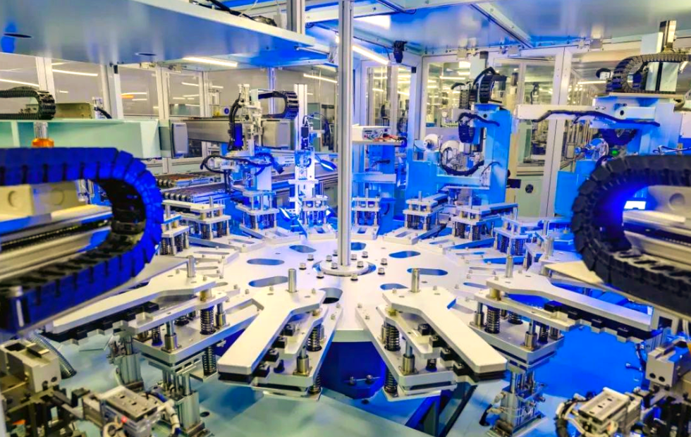
When I study recent progress in solid state battery research, I see a strong signal that the field is moving from laboratory curiosity toward practical cell engineering. A solid state battery replaces the flammable liquid electrolyte of conventional lithium-ion cells with a solid electrolyte. The promise is high energy density and improved intrinsic safety. The difficulty is that solid-solid interfaces do not wet, conform, or self-heal like liquids. Every contact point must be engineered. Every voltage window must be checked. Every pressure condition must be understood. The solid state battery therefore demands a project structure that links fundamental science to manufacturing reality.
1. The Promise and the Boundary Conditions of a Solid State Battery
I define the target of a solid state battery in measurable terms. The first metric is gravimetric energy density. The second is volumetric energy density. The third is safety under abuse. The fourth is cycle life. The fifth is manufacturability. A solid state battery that reaches a high energy density in a small coin cell but fails in a large pouch cell is not yet a product. A solid state battery that passes safety tests but has poor yield is not yet a business. I therefore treat the solid state battery as a system whose performance is bounded by interfaces, transport, mechanics, and process control.
For any cell, I calculate gravimetric energy density as:
$$E_g = \frac{\int_0^Q V(q)\,dq}{m_{\text{cell}}}$$
Here, \(E_g\) is the specific energy in Wh/kg, \(Q\) is the cell capacity, \(V(q)\) is the voltage as a function of charge, and \(m_{\text{cell}}\) is the total cell mass. For a simplified constant-voltage estimate, I use:
$$E_g = \frac{V_{\text{nom}} Q_{\text{nom}}}{m_{\text{cell}}}$$
The volumetric energy density follows a similar logic:
$$E_v = \frac{\int_0^Q V(q)\,dq}{V_{\text{cell}}}$$
These equations seem simple, but they force me to confront every gram and every cubic centimeter. In a solid state battery, the electrolyte, current collectors, packaging, tabs, and stack pressure hardware all compete for mass and volume. The solid state battery may use a lithium metal anode to increase capacity, but that choice also changes the interface chemistry and the safety profile. The solid state battery may use a high-voltage cathode to increase voltage, but that choice narrows the set of compatible electrolytes. The solid state battery may use a thick electrolyte to resist dendrites, but that choice increases resistance. Every gain creates a new constraint.
| Aspect | Conventional Liquid-Electrolyte Lithium-Ion Cell | Solid State Battery |
|---|---|---|
| Electrolyte phase | Liquid with separator | Solid or quasi-solid |
| Interface behavior | Wetting and conformal contact | Solid-solid contact with voids and resistance |
| Safety origin | Flammable organic solvent | Potentially less flammable, but not automatically safe |
| Pressure requirement | Low to moderate | Often high and sometimes uneven |
| Energy density target | About 250 to 300 Wh/kg at mature commercial level | Above 400 Wh/kg and toward 600 Wh/kg in advanced demonstrations |
| Manufacturing maturity | High | Emerging, with process gaps in scale-up |
| Key bottleneck | Energy density ceiling and thermal risk | Interface stability, pressure control, and yield |
I conclude from this comparison that the solid state battery is not a drop-in replacement. It is a new architecture. My planning must therefore begin with architecture choices before individual material optimization. I ask: Is the solid state battery polymer-based, oxide-based, sulfide-based, halide-based, or composite? Is the anode lithium metal, silicon-dominant, or graphite? Is the cathode a layered oxide, a high-voltage spinel, or a lithium-rich manganese-based oxide? Each combination has a different failure mode. Each failure mode requires a different control strategy.
2. Core Scientific Barriers in the Solid State Battery
I have learned to reduce the solid state battery problem into four coupled barriers. The first is interfacial contact. The second is electrochemical stability. The third is ionic transport. The fourth is mechanical integrity. These barriers are not independent. Improving one often worsens another. For example, increasing stack pressure improves contact but may crack the electrolyte. Increasing electrolyte thickness suppresses dendrites but raises resistance. Increasing cathode voltage raises energy but accelerates oxidation. The solid state battery is therefore a multi-objective optimization problem.
The interfacial resistance of a solid state battery can be written in a simplified form as:
$$R_{\text{interface}} = R_{\text{contact}} + R_{\text{charge-transfer}} + R_{\text{film}}$$
The contact resistance depends on the real area of contact:
$$R_{\text{contact}} = \frac{\rho_{\text{eff}}}{A_{\text{real}}}$$
where \(\rho_{\text{eff}}\) is an effective resistivity and \(A_{\text{real}}\) is the true contact area. In a solid state battery, \(A_{\text{real}}\) is often much smaller than the nominal area \(A_{\text{nom}}\). I can approximate the pressure dependence as:
$$A_{\text{real}} = A_{\text{nom}} \left(\frac{P}{H}\right)^m$$
Here, \(P\) is the applied pressure, \(H\) is a hardness-like parameter, and \(m\) is an empirical exponent. This equation tells me why the solid state battery often needs external pressure. It also tells me why pressure must be uniform. If pressure is uneven, some regions of the solid state battery carry most of the current, while other regions remain inactive. That non-uniformity accelerates degradation and creates local hot spots.
The electrochemical stability window of a solid state battery is another central constraint. I define the window as:
$$\Delta E_{\text{window}} = E_{\text{ox}} – E_{\text{red}}$$
A practical solid state battery must have a window wide enough to accommodate the cathode potential and the anode potential. For a high-voltage cathode, \(E_{\text{ox}}\) must be high. For a lithium metal anode, \(E_{\text{red}}\) must be low. If the electrolyte is not thermodynamically stable, it will decompose and form an interphase. Sometimes that interphase is beneficial, but often it adds resistance and consumes lithium. The solid state battery therefore lives with both thermodynamic instability and kinetic protection.
Ionic transport in a solid state battery is described by conductivity:
$$\sigma = \frac{L}{A R_b}$$
where \(L\) is thickness, \(A\) is area, and \(R_b\) is bulk resistance. Temperature dependence often follows an Arrhenius form:
$$\sigma(T) = \sigma_0 \exp\left(-\frac{E_a}{RT}\right)$$
For many polymer electrolytes, the behavior is better described by a Vogel-Tammann-Fulcher relationship:
$$\sigma(T) = A T^{-1/2} \exp\left(-\frac{B}{T-T_0}\right)$$
I pay special attention to the lithium-ion transference number because a solid state battery with high total conductivity but low \(t_+\) can still suffer from concentration polarization. A common method uses:
$$t_+ = \frac{I_{ss}(\Delta V – I_0 R_0)}{I_0(\Delta V – I_{ss} R_{ss})}$$
where \(I_0\) and \(I_{ss}\) are initial and steady-state currents, \(R_0\) and \(R_{ss}\) are initial and steady-state resistances, and \(\Delta V\) is the applied polarization. For a solid state battery, I want a high \(t_+\) because it reduces anion accumulation and smooths lithium deposition.
3. Anion-Rich Solvation and Fluorinated Polyether Electrolytes
In my reading of recent solid state battery advances, one promising direction is the design of a fluorinated polyether electrolyte for a polymer-based solid state battery. The key idea is not simply to add fluorine. The key idea is to control the solvation structure of lithium ions. I describe this as an anion-rich solvation strategy. In a conventional dilute liquid electrolyte, lithium ions are surrounded mainly by solvent molecules. In an anion-rich environment, more anions enter the first solvation shell. That change can lower the barrier for interfacial reactions, improve ion transport, and help form a more stable interphase.
I represent the equilibrium between solvent-separated ion pairs and contact ion pairs or aggregates as:
$$\text{Li}^+(\text{SSIP}) + \text{anion} \rightleftharpoons \text{Li}^+(\text{CIP}) + \text{anion} \rightleftharpoons \text{Li}^+(\text{AGG})$$
A more formal description uses the coordination number \(n\) and the anion-to-lithium ratio \(r\):
$$r = \frac{[\text{anion}]}{[\text{Li}^+]}$$
When \(r\) is high, the solid state battery electrolyte can form anion-rich clusters. These clusters may promote the formation of a fluorine-rich interphase. That interphase can protect the high-voltage cathode and the lithium metal anode. The solid state battery therefore benefits from a designed interphase rather than a random decomposition layer.
For a fluorinated polyether solid state battery, I track three properties at once. The first is the highest occupied molecular orbital and lowest unoccupied molecular orbital gap, which relates to oxidative and reductive stability. The second is the glass transition temperature, which controls polymer chain mobility. The third is the dielectric constant, which influences salt dissociation. I summarize the trade-offs in a table.
| Design Variable | Desired Direction | Effect on Solid State Battery | Possible Penalty |
|---|---|---|---|
| Fluorine content | Moderate to high | Improves oxidative stability and interphase formation | May reduce ionic conductivity if too high |
| Anion-to-lithium ratio | High enough for aggregates | Promotes anion-rich solvation and stable interface | Can increase viscosity and reduce wetting |
| Polymer chain mobility | High above glass transition | Supports ion transport in solid state battery | May reduce mechanical strength |
| Crosslink density | Optimized | Improves dimensional stability | Too high reduces conductivity |
| Electrolyte thickness | Thin but defect-free | Raises energy density | Risk of short circuit and dendrite penetration |
I find the in-situ polymerization route especially interesting for a solid state battery. If the polymer precursor can flow into the electrode pores and then polymerize in place, the solid state battery can achieve better physical contact than a pre-formed solid electrolyte film. The process can be summarized as:
$$\text{precursor liquid} \xrightarrow{\text{thermal initiation}} \text{crosslinked polyether network}$$
The resulting solid state battery has a conformal interface. This reduces contact resistance and improves ion conduction across the boundary. However, I must also control the polymerization rate, temperature uniformity, and residual monomer content. If the reaction is too fast, the solid state battery may develop voids. If it is too slow, the process may not be economically viable. If the temperature is uneven, the solid state battery may have regions with different conductivity and mechanical modulus.
4. Cell-Level Performance and Safety Validation
I do not trust a solid state battery concept until it is demonstrated at the cell level. Coin cells are useful for material screening, but pouch cells reveal the real problems. A pouch cell tests the solid state battery under realistic area, pressure, tab design, and thermal gradients. When I see a demonstration of an 8.96 Ah polymer solid state battery with an energy density of 604 Wh/kg under 1 MPa pressure, I immediately ask about the mass breakdown, the voltage curve, the pressure fixture, and the safety protocol. The numbers are impressive, but I need the engineering context.
Using a nominal voltage of about 3.7 V, I can estimate the cell mass from:
$$m_{\text{cell}} = \frac{V_{\text{nom}} Q_{\text{nom}}}{E_g}$$
Substituting the reported values:
$$m_{\text{cell}} \approx \frac{3.7 \times 8.96}{604} \text{ kg} \approx 0.0549 \text{ kg}$$
This means the solid state battery cell is roughly 54.9 grams if the nominal voltage is 3.7 V. Of course, the actual mass depends on the real voltage curve and the definition of cell mass. The point is that I can use simple equations to test whether a claim is internally consistent. For a solid state battery, this kind of sanity check is essential.
| Parameter | Reported or Estimated Value | Engineering Meaning |
|---|---|---|
| Cell capacity | 8.96 Ah | Large enough to represent a practical solid state battery pouch cell |
| Applied pressure | 1 MPa | Moderate stack pressure, lower than many solid state battery lab fixtures |
| Energy density | 604 Wh/kg | Far above conventional commercial lithium-ion cells |
| Estimated mass at 3.7 V | About 54.9 g | Useful for mass balance and pack-level projection |
| Nail penetration | No fire or explosion | Indicates mechanical abuse tolerance |
| Hot box test | 120 degrees Celsius for 6 hours | Indicates thermal stability in a fully charged state |
Safety is a system property. I cannot conclude that every solid state battery is safe just because one cell passes a nail penetration test. I need to understand the failure sequence. A nail penetration test creates an internal short. The local current density rises. Heat is generated. The temperature increases. If the solid state battery can tolerate the short without propagating to neighboring cells, that is a major advantage. But I still need to test overcharge, overdischarge, external short, crush, vibration, thermal shock, and altitude simulation.
Heat generation in a solid state battery can be approximated by:
$$Q_{\text{gen}} = I^2 R_{\text{int}} + I T \frac{\partial E}{\partial T}$$
The first term is Joule heating. The second term is entropic heat. The total heat is:
$$Q_{\text{total}} = \int_0^t Q_{\text{gen}} dt$$
If heat generation exceeds heat dissipation, the solid state battery temperature rises. If the rise triggers further reactions, thermal runaway can occur. The Arrhenius equation reminds me that reaction rates increase exponentially with temperature:
$$k(T) = A \exp\left(-\frac{E_a}{RT}\right)$$
Therefore, my safety strategy for a solid state battery is to reduce \(R_{\text{int}}\), improve thermal conductivity, design a thermally stable interphase, and introduce reliable shutdown mechanisms. I also use a gated validation plan: material-level screening, single-layer cell testing, multi-layer pouch testing, module testing, and pack testing. Each gate has quantitative exit criteria. The solid state battery must earn its way to the next level.
5. Work Breakdown Structure for a Solid State Battery Program
I build a work breakdown structure for a solid state battery program before I allow large spending. The WBS is not a bureaucratic document. It is a thinking tool. It forces me to identify every deliverable, every dependency, and every interface. I divide the program into phases: concept, materials, cell design, prototyping, pilot scale-up, validation, and production. For each phase, I define tasks, outputs, owners, and exit criteria. I also define what must be true before the next phase begins.
| Phase | Key Tasks | Primary Deliverables | Exit Criteria |
|---|---|---|---|
| Concept | Market requirements, target specification, chemistry screening, patent landscape | Target document and architecture trade study | Approved target for energy density, safety, cost, and life |
| Materials | Polymer synthesis, salt selection, additive screening, interfacial coating | Candidate solid state battery electrolyte and electrode formulations | Conductivity, voltage window, and cycle life meet screening targets |
| Cell design | Electrode formulation, stacking, tab design, pressure fixture, thermal model | Design freeze for a solid state battery cell | Energy density and resistance targets validated in single-layer cells |
| Prototyping | Coin cell, single-layer pouch, multi-layer pouch, formation protocol | Testable solid state battery prototypes | Capacity, rate, and safety meet gate criteria |
| Pilot scale-up | Coating, lamination, stacking, packaging, in-situ polymerization | Pilot line data and process specification | Yield and consistency reach pilot targets |
| Validation | Abuse testing, life testing, environmental testing, certification | Qualification report for the solid state battery | Compliance with internal and external standards |
| Production | Quality control, supplier development, cost reduction, automation | Stable production and continuous improvement | OEE, Cp, Cpk, and cost targets achieved |
I use stage gates to prevent premature scaling. A common mistake in solid state battery development is to move to a large format before the interface is understood. When that happens, the solid state battery may show good initial capacity but fail after a few cycles. The root cause is often hidden in the materials or the formation protocol. I therefore require that every solid state battery candidate pass a defined set of tests before it enters the pilot line. These tests include electrochemical impedance spectroscopy, cycling at multiple temperatures, pressure-dependent performance, and post-mortem analysis.
I also define the critical path. For a solid state battery, the critical path usually runs through electrolyte synthesis, interface optimization, cell design, and scale-up. If the electrolyte is not stable, cell design cannot be frozen. If the cell design is not frozen, tooling cannot be ordered. If tooling is late, validation slips. I therefore track the critical path with network logic and float calculations. The classic project management formulas apply:
$$ES = \max(EF_{\text{predecessors}})$$
$$EF = ES + D$$
$$LS = LF – D$$
$$TF = LS – ES$$
Here, \(ES\) is early start, \(EF\) is early finish, \(LS\) is late start, \(LF\) is late finish, \(D\) is duration, and \(TF\) is total float. For a solid state battery program, I protect the critical path by assigning the best scientists and engineers to interface work and by keeping contingency resources available.
6. Risk Management and FMEA for the Solid State Battery
I treat risk management as an active control loop. I do not simply list risks. I score them, assign owners, define triggers, and update the register at every gate. For a solid state battery, the highest risks are often interfacial resistance, dendrite penetration, electrolyte oxidation, thermal runaway, process drift, and cost escalation. I use failure mode and effects analysis to prioritize actions. The risk priority number is:
$$RPN = S \times O \times D$$
where \(S\) is severity, \(O\) is occurrence, and \(D\) is detection difficulty. A high RPN means I need a mitigation or a detection improvement before proceeding. I also use fault tree analysis for safety. For example, the top event “solid state battery fire” can be traced to internal short, overcharge, external short, or thermal abuse. Each branch has its own probability and consequence.
| Risk | Cause | Effect on Solid State Battery | Mitigation | Detection |
|---|---|---|---|---|
| High interfacial resistance | Poor solid-solid contact, voids, surface films | Low power, low capacity utilization, heat | In-situ polymerization, interlayer coating, optimized pressure | Impedance spectroscopy, pressure-cell testing |
| Dendrite penetration | Non-uniform lithium deposition, defects, low modulus | Internal short, safety failure | Mechanical reinforcement, high transference number, uniform pressure | Post-mortem imaging, voltage relaxation, coulombic efficiency |
| Electrolyte oxidation | High cathode voltage, unstable anion, poor interphase | Capacity fade, gas generation, resistance rise | Fluorinated polyether, cathode coating, anion-rich solvation | Cyclic voltammetry, XPS, online gas analysis |
| Thermal runaway | Internal short, overcharge, external heat | Fire, explosion, program delay | Thermal barrier, shutdown separator, safe cell design | Nail penetration, hot box, ARC testing |
| Scale-up drift | Non-uniform coating, lamination, curing | Low yield, inconsistent solid state battery performance | SPC, design of experiments, inline metrology | Inline inspection, Cp and Cpk tracking |
| Cost escalation | Expensive salts, low yield, complex processing | Poor commercial viability | Supplier qualification, yield improvement, material reduction | Cost model, should-cost analysis |
I also prepare emergency response plans. For a solid state battery, an emergency plan may include fire suppression, gas detection, cell isolation, and safe disposal. Even if the solid state battery is intrinsically safer than a liquid-electrolyte cell, it still stores significant energy. I do not confuse “safer” with “risk-free.” I design for the worst credible event and then verify that the consequences are contained.
7. Manufacturing Scale-Up and Quality Control
I believe the solid state battery will be won or lost in manufacturing. A laboratory solid state battery can be assembled by hand with excessive pressure and long formation times. A commercial solid state battery must be produced at high speed, high yield, and low cost. The process steps include slurry preparation, electrode coating, drying, calendering, electrolyte application, stacking, lamination, packaging, formation, aging, and testing. Each step affects the solid state battery interface. Each step creates data that I can use for control.
I model the cell cost as:
$$C_{\text{cell}} = C_{\text{mat}} + C_{\text{proc}} + C_{\text{yield}} + C_{\text{qual}}$$
The yield penalty is especially important:
$$C_{\text{yield}} = \frac{C_{\text{raw}}}{Y}$$
where \(Y\) is the yield. If the solid state battery yield is 60 percent, the effective material cost is nearly 1.67 times the raw material cost. If the yield rises to 90 percent, the penalty falls to 1.11 times. This simple equation explains why I invest heavily in inline inspection and statistical process control. A small defect in the solid state battery electrolyte film can ruin an entire cell. A minor variation in pressure can create a local short. A small amount of moisture can degrade a sulfide solid state battery. The process window is narrow, and I must control it.
I use statistical process control to monitor critical parameters. Two common capability indices are:
$$C_p = \frac{USL – LSL}{6\sigma}$$
$$C_{pk} = \min\left(\frac{USL – \mu}{3\sigma}, \frac{\mu – LSL}{3\sigma}\right)$$
For a solid state battery, I want \(C_{pk}\) above 1.33 for critical dimensions such as electrolyte thickness, electrode loading, and stack pressure. If \(C_{pk}\) is low, the process is not capable, even if the average looks acceptable. I also use overall equipment effectiveness:
$$OEE = A \times P \times Q$$
where \(A\) is availability, \(P\) is performance, and \(Q\) is quality. I track OEE for every solid state battery line. If availability is high but quality is low, the line is producing waste. If quality is high but performance is low, the line is too slow. I need all three factors to be high.
| Process Step | Critical Parameter | Control Method | Impact on Solid State Battery |
|---|---|---|---|
| Slurry mixing | Solid content, viscosity, dispersion | Inline rheology, particle size analysis | Uniform electrode and interface |
| Electrode coating | Wet thickness, drying profile | Beta gauge, thermal imaging | Capacity balance and rate performance |
| Calendering | Density, porosity, surface roughness | Online thickness and hardness | Contact area and ion transport |
| Electrolyte application | Thickness, defects, curing degree | Optical inspection, impedance mapping | Resistance and safety |
| Stacking and lamination | Alignment, pressure, temperature | Vision system, force sensors | Uniform current distribution |
| Formation | Current, voltage, temperature, pressure | Recipe control, data logging | Interphase quality and cycle life |
| Final testing | Capacity, resistance, self-discharge | Automated test channels | Sorting and reliability |
I also design for traceability. Every solid state battery cell should have a digital record of its materials, process parameters, and test results. If a field failure occurs, I need to trace it back to a specific batch, machine, and shift. Without traceability, I cannot improve. With traceability, I can use machine learning to identify hidden correlations. For example, a slight change in curing temperature may not affect initial capacity but may reduce cycle life after 500 cycles. Only a well-designed data system can reveal that relationship.
8. Data, Learning, and Continuous Improvement
I treat every solid state battery experiment as a source of data. I do not run experiments without a hypothesis. I do not collect data without a plan for analysis. I use design of experiments to vary multiple factors efficiently. I use response surface methodology to find optima. I use accelerated life testing to estimate degradation. The solid state battery is complex, so I need statistical thinking as much as electrochemical thinking.
I use a learning curve model to forecast cost and performance improvement:
$$C_n = C_1 n^{\log_2 b}$$
Here, \(C_n\) is the cost of the \(n\)-th unit, \(C_1\) is the first-unit cost, and \(b\) is the learning rate. If the solid state battery learning rate is 85 percent, then each doubling of cumulative production reduces cost to 85 percent of the previous level. This is why pilot lines and early production are so important. They create the data and experience that drive the learning curve.
I also use a simple degradation model. Capacity fade often follows a power law:
$$Q(n) = Q_0 – k n^z$$
where \(Q(n)\) is capacity after \(n\) cycles, \(Q_0\) is initial capacity, \(k\) is a degradation coefficient, and \(z\) is an exponent. For a solid state battery, \(z\) may change when the dominant degradation mode changes. Early cycling may be dominated by interface formation. Later cycling may be dominated by mechanical degradation or lithium inventory loss. I therefore fit the model piecewise and look for breakpoints.
I maintain a lessons-learned database. When a solid state battery fails, I record the failure mode, the root cause, the corrective action, and the verification result. I share these lessons across teams. I believe that not repeating the mistakes of others is a form of progress. A solid state battery program that learns faster than its competitors will win, even if its initial technology is not superior. The ability to learn is a strategic asset.
9. Economic and Strategic Assessment of the Solid State Battery
I evaluate the solid state battery not only by energy density but by value. A high-energy solid state battery may be worth a premium in electric aviation, long-range electric vehicles, premium consumer electronics, and defense applications. It may be less competitive in low-cost stationary storage where cost per kilowatt-hour dominates. I therefore segment the market and define the minimum viable performance for each segment. The solid state battery does not need to beat liquid lithium-ion everywhere. It needs to win where its advantages matter most.
I use a levelized cost model:
$$LCOE = \frac{C_{\text{capital}} + C_{\text{operating}} + C_{\text{replacement}}}{E_{\text{total}}}$$
For a solid state battery in a vehicle, the relevant metric may be cost per kilometer or cost per year of ownership. For a solid state battery in a grid application, the relevant metric may be cost per cycle. I therefore translate technical metrics into economic metrics early. This prevents the program from optimizing the wrong variable.
| Application | Key Requirement | Solid State Battery Advantage | Main Barrier |
|---|---|---|---|
| Electric aviation | Very high energy density, high safety | Potential for above 400 Wh/kg | Cost, cycle life, certification |
| Long-range electric vehicles | High energy density, fast charge, safety | Higher range and improved abuse tolerance | Manufacturing scale, low-temperature performance |
| Premium consumer electronics | Thin form factor, high volumetric density | Compact design and safety | Cost and supply chain |
| Grid storage | Low cost, long cycle life | Safety advantage | Cost per kWh, cycle life |
| Defense and aerospace | Reliability, wide temperature range | Safety and energy density | Qualification time, cost |
I also consider supply chain risk. A solid state battery may require lithium metal, solid electrolytes, fluorinated polymers, specialty salts, and advanced packaging. Some of these materials are scarce or concentrated in specific regions. I therefore map the supply chain, qualify multiple suppliers, and design for material reduction. I do not want a technically superior solid state battery that cannot be produced at scale because of a single critical material.
10. My Integrated Control Framework for a Solid State Battery Program
I combine technical and managerial controls into one framework. The framework has four layers. The first layer is architecture: chemistry, cell format, and target specification. The second layer is interface: contact, stability, transport, and mechanics. The third layer is process: yield, capability, cost, and traceability. The fourth layer is validation: safety, life, environmental, and field performance. Each layer has metrics, owners, and gates. I review the solid state battery program weekly at the technical level and monthly at the portfolio level.
I use earned value management to track progress:
$$CV = EV – AC$$
$$SV = EV – PV$$
$$CPI = \frac{EV}{AC}$$
$$SPI = \frac{EV}{PV}$$
$$EAC = \frac{BAC}{CPI}$$
Here, \(EV\) is earned value, \(AC\) is actual cost, \(PV\) is planned value, \(BAC\) is budget at completion, and \(EAC\) is estimate at completion. If \(CPI\) is below 1, the solid state battery program is over budget. If \(SPI\) is below 1, it is behind schedule. These indicators do not replace technical judgment, but they trigger questions. Why is cost high? Is it due to yield loss, material cost, or rework? Why is schedule slipping? Is it due to a critical experiment, a supplier delay, or a design change? I want answers, not excuses.
| Control Area | Tool | Core Formula | Purpose in Solid State Battery Program |
|---|---|---|---|
| Scope | WBS | Not applicable | Decompose work into manageable deliverables |
| Schedule | Critical path | \(TF = LS – ES\) | Protect interface and scale-up activities |
| Cost | EVM | \(CPI = EV/AC\) | Detect budget drift early |
| Quality | SPC | \(C_{pk} = \min\left(\frac{USL-\mu}{3\sigma}, \frac{\mu-LSL}{3\sigma}\right)\) | Ensure process capability for solid state battery production |
| Risk | FMEA | \(RPN = S \times O \times D\) | Prioritize mitigation actions |
| Safety | Fault tree | Not applicable | Trace failure paths and design barriers |
| Learning | Lessons learned | \(C_n = C_1 n^{\log_2 b}\) | Accelerate cost and performance improvement |
I insist on pre-mortems. Before a major solid state battery milestone, I ask the team to imagine that the milestone has failed. What caused the failure? Was it an interface problem? A process drift? A safety event? A supply chain delay? By identifying failure causes in advance, I can design preventive actions. I also insist on post-mortems. After every milestone, I ask what worked, what did not, and what should change. I document the answers in a searchable database. This is how I turn experience into organizational capability.
11. A Practical Roadmap for Solid State Battery Development
I propose a practical roadmap for a solid state battery program. The first year focuses on materials and interface science. The second year focuses on cell design and prototype validation. The third year focuses on pilot scale-up and safety qualification. The fourth year focuses on production readiness and cost reduction. This roadmap is not rigid. It is a baseline that I update as data arrive. The solid state battery field is moving quickly, so I build flexibility into the plan.
| Time Horizon | Primary Objective | Key Milestones | Success Metric |
|---|---|---|---|
| Months 0 to 12 | Materials and interface discovery | Electrolyte candidate, coating, solvation design | Conductivity, voltage window, interfacial resistance |
| Months 12 to 24 | Cell design and prototyping | Single-layer and multi-layer pouch cells | Energy density, rate, cycle life in solid state battery prototypes |
| Months 24 to 36 | Pilot scale-up and safety | Pilot line, formation protocol, abuse testing | Yield, Cp and Cpk, nail penetration, hot box |
| Months 36 to 48 | Production readiness | Supplier qualification, automation, cost model | OEE, cost per kWh, field reliability |
I also define technical readiness levels. A solid state battery at TRL 3 has a proof of concept. At TRL 5, it has a relevant environment demonstration. At TRL 7, it has a system prototype. At TRL 9, it is in production. I use these levels to communicate with stakeholders. I do not claim TRL 7 when the solid state battery has only been tested as a coin cell. I do not claim commercial readiness when the yield is 40 percent. Honest assessment is essential for resource allocation.
12. Conclusion: Discipline Makes the Solid State Battery Real
I believe the solid state battery will become a major technology, but not because of a single miracle material. It will become real because teams learn to control interfaces, manage pressure, stabilize high-voltage chemistry, scale up manufacturing, and validate safety with rigorous data. The solid state battery is a system. Its performance is limited by the weakest interface. Its cost is driven by the lowest yield. Its safety is determined by the most severe credible failure. Its schedule is controlled by the critical path through materials, design, and process.
My first-person commitment is simple. I will plan before I build. I will measure before I claim. I will decompose the work, compare every node, and keep management attention on the details that matter. I will use tables, formulas, and data to make decisions. I will maintain contingency plans and review lessons learned. I will treat every solid state battery failure as a source of information and every solid state battery success as a reason to verify further. In the end, the solid state battery will not be delivered by optimism alone. It will be delivered by disciplined engineering, repeated learning, and the refusal to let small defects become large failures.