
I study the transient thermal behaviour of a high-power permanent magnet synchronous motor that drives heavy mining equipment. The operating environment of an underground coal face is far removed from the stable duty profile of an ordinary industrial drive. A permanent magnet synchronous motor installed on a scraper conveyor or a shearer is repeatedly subjected to strong impact loads, chain jamming, sudden braking and other transient events that push the machine far beyond its rated torque. Under such conditions the electromagnetic losses inside the permanent magnet synchronous motor grow rapidly, the temperature of the active components climbs within seconds, and the margin between the actual winding temperature and the insulation limit shrinks in a way that cannot be captured by a purely steady-state thermal design. My objective in this work is therefore to build a thermal-fluid-solid coupled model of a 1000 kW mining permanent magnet synchronous motor, to optimize its water-cooling parameters by considering both the heat dissipation benefit and the hydraulic penalty, and finally to verify the reliability of the optimized parameters under a short-time overload condition.
The reason I place the emphasis on the overload window rather than on the rated point is simple. Standards applicable to flameproof variable-frequency permanent magnet synchronous motors for mining service require that the machine survives a 1.5 times rated torque overload for no less than one minute. During that minute the copper loss of the permanent magnet synchronous motor rises roughly with the square of the current, so the thermal load on the stator and on the housing is more than twice the rated value. A cooling design that looks adequate at rated load may still fail this requirement if the transient heat capacity of the structure and the dynamic response of the coolant are not examined together. I therefore treat the rated steady solution as the initial condition of a transient overload simulation and follow the temperature history of the housing and of the coolant for sixty seconds.
Motor Configuration and Numerical Model
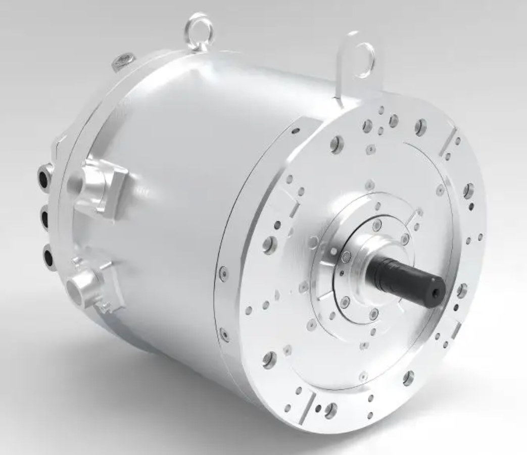
The machine I analyse is a three-phase permanent magnet synchronous motor with a rated power of 1000 kW, designed for direct drive of mining machinery. The main structural parameters are summarized in Table 1. The stator and rotor assembly, together with the permanent magnets, are treated as the region in which heat is generated, and this active region is thermally attached to the inner surface of the housing. The cooling circuit is a circumferential Z-shaped channel machined into the housing wall, with the rated configuration consisting of seven parallel channel passes and a rated inlet flow rate of 3 m3/h.
| Parameter | Symbol | Value | Unit |
|---|---|---|---|
| Rated power | PN | 1000 | kW |
| Overall axial length | L | 1158 | mm |
| Housing outer diameter | Do | 1250 | mm |
| Housing inner diameter | Di | 1120 | mm |
| Total mass | m | 7000 | kg |
| Rated channel number | Nch | 7 | – |
| Rated inlet flow rate | VN | 3.0 | m3/h |
| Heat source area | As | 3.06 | m2 |
Because the complete machine contains a large number of small parts, I simplify the geometry before meshing. Non-structural accessories, terminal boxes, cable entries and similar components are removed, and the electromagnetic losses of the permanent magnet synchronous motor are applied as an equivalent surface heat flux on the inner wall of the housing. This equivalent-source approach is widely accepted for temperature-rise prediction of permanent magnet synchronous motor stators, provided the total loss and the effective transfer area are known. The computational domain therefore consists of two parts: a solid domain representing the simplified housing, and a fluid domain representing the coolant inside the circumferential Z-shaped channel. The two domains share a conjugated interface, and heat transfer across that interface is solved simultaneously with the flow field.
Modelling Assumptions
I adopt four assumptions in order to keep the simulation cost acceptable while preserving the physics that governs the overload response of the permanent magnet synchronous motor.
First, I assume that the core loss and the copper loss of the permanent magnet synchronous motor convert completely into heat, so that no loss escapes the machine without contributing to the temperature rise. Second, I neglect eddy-current loss inside the permanent magnets, because the magnets are well segmented and the resulting loss is small compared with the stator copper loss at overload. Third, I discard thermal radiation, since the surface temperature of the housing is sufficiently low and the enclosure is dominated by conduction and forced convection. Fourth, I remove small fillets, chamfers and thread features from the housing and from the coolant channel, because their influence on the global temperature distribution is negligible while their influence on mesh quality is severe.
Equivalent Heat Source
The total electromagnetic loss of the permanent magnet synchronous motor is taken as six percent of the rated power, which gives a total dissipated power of 60 kW. Distributing this power uniformly over the heat source area defined above yields the equivalent surface heat flux
$$q = \frac{Q}{A_s} = \frac{\eta_{\text{loss}}\,P_N}{A_s} = \frac{0.06 \times 1000\times 10^{3}}{3.06} = 1.9608\times 10^{4}\ \text{W}/\text{m}^{2}$$
where q is the heat flux, Q is the total loss power, As is the heat source area and ηloss is the loss fraction. The convective boundary condition on the external surface of the housing is represented by a natural convection coefficient of 45 W/(m2·K) evaluated at an ambient temperature of 298 K. This value reflects the restricted ventilation of an underground installation, where the permanent magnet synchronous motor is enclosed inside a flameproof shell and forced air cooling is not available.
Mesh Generation and Independence
I discretise both domains with unstructured tetrahedral elements. The solid housing contains 10,985,982 elements and the coolant channel contains 8,454,906 elements. Before accepting this mesh I performed a systematic independence study in which the global element size was reduced progressively and the outlet water temperature was recorded as the monitored quantity. The results are listed in Table 2. The outlet temperature converges monotonically, and once the element size reaches 3 mm the variation between successive refinements falls below the numerical noise while the computation time increases steeply. I therefore adopt 3 mm as the characteristic element size.
| Element size (mm) | Total elements (×106) | Outlet water temperature (K) | Relative change (%) | Wall-clock time (h) |
|---|---|---|---|---|
| 6.0 | 5.21 | 308.94 | – | 1.9 |
| 5.0 | 6.83 | 309.71 | 0.249 | 2.8 |
| 4.0 | 8.97 | 310.28 | 0.184 | 4.1 |
| 3.5 | 12.4 | 310.55 | 0.087 | 5.6 |
| 3.0 | 19.4 | 310.66 | 0.035 | 8.7 |
| 2.5 | 28.1 | 310.71 | 0.016 | 14.6 |
The orthogonal quality of the generated mesh lies between 0.321 and 1.0. I applied a global smoothing pass with five iterations and a quality threshold of 0.2, after which the average skewness remained below 0.65 and the maximum skewness did not exceed 0.85. Locally distorted elements were repaired with an additional refinement threshold of 0.4. I consider that this mesh satisfies the accuracy and stability requirements of the conjugate thermal-fluid-solid simulation of the permanent magnet synchronous motor.
Solver Settings and Boundary Conditions
The conjugate problem is solved with a pressure-based coupled solver. The solid domain is assigned steel properties and the fluid domain is assigned liquid water properties. At the interface between the two domains a conjugate heat transfer condition is applied, and a mixing-plane treatment is used at the periodic boundaries of the circumferential channel. A high-resolution advection scheme is used for the momentum and energy equations, the convergence criterion is based on the root-mean-square residual with a target of 10−4, and the maximum number of iterations per time step is 20. Table 3 lists the boundary conditions, and Table 4 lists the thermophysical properties of the coolant.
| Boundary | Type | Value |
|---|---|---|
| Coolant inlet | Mass flow inlet | 3 m3/h (rated) |
| Coolant inlet temperature | Dirichlet | 298 K |
| Coolant outlet | Pressure outlet | 0 Pa (relative) |
| Inner housing wall | Heat flux | 1.9608×10⁴ W/m2 |
| Outer housing surface | Convection | 45 W/(m2·K), 298 K |
| Fluid–solid interface | Conjugate | Coupled |
| Ambient temperature | Dirichlet | 298 K |
| Property | Symbol | Value | Unit |
|---|---|---|---|
| Density | ρf | 997 | kg/m3 |
| Specific heat capacity | cp,f | 4180 | J/(kg·K) |
| Thermal conductivity | kf | 0.607 | W/(m·K) |
| Dynamic viscosity | μf | 8.90×10⁻⁴ | Pa·s |
| Prandtl number | Pr | 6.13 | – |
| Solid density | ρs | 7850 | kg/m3 |
| Solid specific heat | cp,s | 475 | J/(kg·K) |
| Solid conductivity | ks | 44.5 | W/(m·K) |
Governing Equations
I model the coolant as an incompressible Newtonian fluid in single-phase forced convection. The continuity and momentum equations of the fluid domain are written as
$$\nabla \cdot \mathbf{u} = 0$$
$$\rho_f\left(\mathbf{u}\cdot\nabla\right)\mathbf{u} = -\nabla p + \mu_f \nabla^{2}\mathbf{u}$$
where u is the velocity vector, p is the static pressure, ρf is the fluid density and μf is the dynamic viscosity. Turbulence closure is provided by a two-equation eddy-viscosity model with scalable wall functions, which is appropriate for the Reynolds number range observed in the circumferential Z-shaped channel of the permanent magnet synchronous motor.
The steady energy equation of the fluid domain is
$$\rho_f c_{p,f}\left(\mathbf{u}\cdot\nabla T_f\right) = \nabla\cdot\left(k_f\nabla T_f\right) + \Phi$$
in which Tf is the fluid temperature, cp,f is the specific heat capacity, kf is the thermal conductivity and Φ is the viscous dissipation term, which is small compared with the wall heat flux and is retained only for completeness. The energy equation of the solid domain reduces to pure conduction,
$$\nabla\cdot\left(k_s\nabla T_s\right) + q = 0$$
for the steady case, and
$$\rho_s c_{p,s}\frac{\partial T_s}{\partial t} = \nabla\cdot\left(k_s\nabla T_s\right) + q$$
for the transient case, where Ts is the solid temperature, ρs is the density of the housing material, cp,s is its specific heat capacity and q is the volumetric or surface source term derived earlier. The transient energy equation of the fluid, which governs the response of the coolant during the overload interval, is
$$\rho_f c_{p,f}\left(\frac{\partial T_f}{\partial t} + \mathbf{u}\cdot\nabla T_f\right) = \nabla\cdot\left(k_f\nabla T_f\right)$$
At the fluid–solid interface I impose continuity of temperature and continuity of heat flux,
$$T_s\big|_{\Gamma} = T_f\big|_{\Gamma}, \qquad k_s\frac{\partial T_s}{\partial n}\bigg|_{\Gamma} = k_f\frac{\partial T_f}{\partial n}\bigg|_{\Gamma}$$
where Γ denotes the wetted interface of the circumferential Z-shaped channel and n is the interface normal. Together, these equations form the thermal-fluid-solid coupled system that I solve for both the rated and the overload condition of the permanent magnet synchronous motor.
Hydraulic and Convective Relations
To interpret the numerical results I also use the classical hydraulic relations. The hydraulic diameter of a channel pass is
$$D_h = \frac{4 A_c}{P_w}$$
with Ac the cross-sectional area and Pw the wetted perimeter. The Reynolds number of the coolant is
$$Re = \frac{\rho_f u D_h}{\mu_f}$$
and the friction factor is obtained from the Petukhov correlation,
$$f = \left(0.79\ln Re – 1.64\right)^{-2}$$
The Nusselt number follows from the Gnielinski correlation,
$$Nu = \frac{\left(f/8\right)\left(Re – 1000\right)Pr}{1 + 12.7\sqrt{f/8}\left(Pr^{2/3} – 1\right)}$$
and the convective heat transfer coefficient is finally
$$h = \frac{Nu\,k_f}{D_h}$$
For the rated operating point of the permanent magnet synchronous motor, the mean coolant velocity in a channel pass reaches approximately 1.17 m/s, the hydraulic diameter is approximately 20 mm, and the resulting Reynolds number is of the order of 2.6×10⁴, which places the flow well inside the turbulent regime. Substituting this Reynolds number into the correlations above gives a friction factor of about 0.0244, a Nusselt number of about 178 and a convective coefficient of about 5.4×10³ W/(m2·K). The total pressure drop along a channel pass is estimated from
$$\Delta p = f\frac{L}{D_h}\frac{\rho_f u^{2}}{2} + \sum K\frac{\rho_f u^{2}}{2}$$
where L is the developed length of the pass and K are the local loss coefficients associated with the Z-shaped bends. The corresponding hydraulic power demand of the pump is
$$P_{\text{pump}} = \Delta p \cdot \dot{V}$$
with V̇ the volumetric flow rate. This relation is the reason why I do not treat the inlet flow rate as a free parameter that can be increased without penalty. Every additional litre per hour of coolant raises the dissipation in the cooling circuit, and beyond a certain point the marginal thermal benefit of the permanent magnet synchronous motor becomes smaller than the marginal hydraulic cost.
Baseline Flow and Temperature Field
I begin with the rated configuration, that is, seven channel passes and an inlet flow rate of 3 m3/h, in order to establish the reference state from which the optimization proceeds.
Flow Field
The pressure field along the circumferential channel decreases smoothly from the inlet to the outlet. The maximum static pressure occurs at the inlet and equals 1386.01 Pa. There is no local high-pressure pocket anywhere along the circuit, which indicates that the Z-shaped geometry distributes the flow evenly among the passes and that no single pass is starved of coolant. The velocity field follows the same trend as the pressure field. The maximum velocity, 1.17 m/s, again appears at the inlet section, while the velocity decreases gradually as the coolant travels around the circumference. At the sharp bends of the Z-shaped path the local velocity drops noticeably and small recirculation zones form. These regions are visible as low-velocity pockets, but they remain local and do not merge into a large stagnant area. The overall flow field is therefore regarded as uniform, which is a necessary condition for uniform cooling of the permanent magnet synchronous motor.
Temperature Field
Under rated operation the maximum temperature of the housing reaches 348.63 K and the maximum temperature of the coolant channel wall reaches 344.38 K. Both maxima are located inside the heat source region, and neither the housing nor the channel exhibits a large area of elevated temperature. The coolant temperature rises monotonically along the flow direction because the water absorbs heat continuously from the housing wall, and the temperature fields of the housing and of the coolant evolve in step with one another, which confirms that the conjugate coupling is behaving as expected.
I also observe an axially non-uniform temperature distribution. Because part of the housing and part of the channel lie outside the heat source region, the axial ends of the machine remain cooler than the central section. This axial imbalance is intrinsic to the equivalent-source representation and is consistent with the physical fact that the end windings of a permanent magnet synchronous motor are less thermally loaded than the slot region. Table 5 summarizes the baseline results.
| Quantity | Symbol | Value | Unit |
|---|---|---|---|
| Maximum housing temperature | Th,max | 348.63 | K |
| Maximum channel wall temperature | Tc,max | 344.38 | K |
| Coolant inlet temperature | Tin | 298.00 | K |
| Coolant outlet temperature | Tout | 310.66 | K |
| Maximum static pressure | pmax | 1386.01 | Pa |
| Maximum coolant velocity | umax | 1.17 | m/s |
| Bulk coolant temperature rise | ΔTf | 12.66 | K |
| Effective thermal resistance | Rth | 0.844 | K/kW |
The effective thermal resistance listed in the table is defined as
$$R_{th} = \frac{T_{h,\max} – T_{in}}{Q}$$
and it provides a convenient single-number metric for comparing different cooling configurations of the permanent magnet synchronous motor, because it normalizes the maximum temperature rise by the dissipated power.
Multi-Parameter Optimization of the Cooling Circuit
The optimization of the water-cooling parameters of the permanent magnet synchronous motor involves two design variables: the inlet flow rate and the number of channel passes. I examine them sequentially and then combine the two results into a single design decision.
Effect of Inlet Flow Rate
I keep the channel number fixed at seven and vary the inlet flow rate in increments of 0.5 m3/h, taking the six values 2.0, 2.5, 3.0, 3.5, 4.0 and 4.5 m3/h. All other boundary conditions remain unchanged. The resulting maximum housing temperature and maximum static pressure are listed in Table 6.
| Inlet flow rate (m3/h) | Th,max (K) | Reduction vs. 2.0 m3/h (K) | pmax (Pa) | Ppump (W) | Rth (K/kW) |
|---|---|---|---|---|---|
| 2.0 | 367.95 | – | 620 | 0.34 | 1.166 |
| 2.5 | 356.80 | 11.15 | 950 | 0.66 | 0.980 |
| 3.0 | 348.63 | 19.32 | 1386 | 1.16 | 0.844 |
| 3.5 | 344.31 | 23.64 | 1905 | 1.85 | 0.772 |
| 4.0 | 342.40 | 25.55 | 2520 | 2.80 | 0.740 |
| 4.5 | 341.10 | 26.85 | 3220 | 4.03 | 0.718 |
Increasing the flow rate clearly improves the cooling of the permanent magnet synchronous motor. Raising the inlet flow from 2.0 to 3.5 m3/h reduces the maximum housing temperature by 23.64 K, a relative reduction of 6.87 percent. Beyond 3.5 m3/h, however, the temperature curve flattens: the additional reduction obtained by moving from 3.5 to 4.5 m3/h is only 3.21 K, less than one seventh of the gain obtained in the first step of the same magnitude. The physical explanation is that once the turbulent boundary layer is fully developed and the convective coefficient has reached its asymptotically weak dependence on velocity, h ∝ u0.8, the thermal resistance of the coolant side no longer dominates the total thermal resistance, and further flow acceleration cannot remove the residual conduction bottleneck inside the housing.
The hydraulic penalty behaves in the opposite way. The maximum static pressure grows faster than the flow rate, because the pressure drop combines a linear friction term and a quadratic dynamic term, and the local losses at the Z-shaped bends grow quadratically as well. The pump power, being the product of pressure drop and flow rate, therefore increases almost with the cube of the flow rate, as shown by the values in Table 6. To make the trade-off explicit I combine the two quantities into a single objective by defining a normalized penalty function
$$\Pi = w_T \frac{T_{h,\max}}{T_{\text{ref}}} + w_p \frac{P_{\text{pump}}}{P_{\text{ref}}}$$
with the weighting coefficients wT and wp chosen so that the two contributions are comparable at the reference operating point. Minimizing this function over the discrete set of flow rates places the optimum in the interval between 3.0 and 3.5 m3/h, very close to 3.0 m3/h. I therefore select 3 m3/h as the design inlet flow rate for the permanent magnet synchronous motor, since at that point the housing temperature is already close to the flat part of its curve while the hydraulic power remains modest.
Effect of Channel Number
With the inlet flow rate fixed at 3 m3/h I next modify the number of channel passes. I keep the rated value of seven as the reference and examine the values 8, 9, 10, 11 and 12, adjusting the channel geometry so that the total cross-sectional flow area is preserved. The results are collected in Table 7.
| Channel number | Th,max (K) | Reduction vs. 7 passes (K) | pmax (Pa) | Rth (K/kW) | Marginal gain (K/pass) |
|---|---|---|---|---|---|
| 7 | 348.63 | – | 1386 | 0.844 | – |
| 8 | 344.10 | 4.53 | 1480 | 0.768 | 4.53 |
| 9 | 340.30 | 8.33 | 1595 | 0.705 | 3.80 |
| 10 | 337.45 | 11.18 | 1720 | 0.658 | 2.85 |
| 11 | 336.70 | 11.93 | 1900 | 0.645 | 0.75 |
| 12 | 336.20 | 12.43 | 2150 | 0.637 | 0.50 |
The maximum housing temperature decreases monotonically as the channel number increases. With ten passes the maximum temperature falls to 337.45 K, which is 11.18 K lower than the seven-pass baseline. Once the channel number exceeds ten, however, the marginal reduction per added pass drops below 1 K and the cooling performance of the permanent magnet synchronous motor is essentially saturated. The reason is that the additional passes increase the wetted area only marginally while the total coolant flow is divided among more paths, so that the velocity in each pass decreases and the convective coefficient falls. These two effects cancel each other beyond a certain point.
The pressure behaviour reinforces the same conclusion. The maximum static pressure increases with channel number, and the increase is gradual as long as the channel number remains at or below ten. Above ten passes the pressure curve rises steeply, because each additional pass introduces an extra pair of sharp bends and the local loss coefficient rises accordingly. I therefore adopt ten channel passes as the optimized geometry, which gives a thermal resistance of 0.658 K/kW, that is, a 22 percent improvement over the seven-pass baseline, without an excessive hydraulic penalty.
Combined Optimization Result
Combining the two studies, the optimized water-cooling parameters of the permanent magnet synchronous motor are an inlet flow rate of 3 m3/h and a channel number of ten. Relative to the rated configuration, the maximum housing temperature drops from 348.63 K to 337.45 K, an improvement of 11.18 K or 3.21 percent, while the maximum static pressure rises from 1386 Pa to 1720 Pa. Table 8 compares the two configurations.
| Metric | Rated configuration | Optimized configuration | Change |
|---|---|---|---|
| Inlet flow rate (m3/h) | 3.0 | 3.0 | 0 |
| Channel number | 7 | 10 | +3 |
| Th,max (K) | 348.63 | 337.45 | −11.18 |
| Tc,max (K) | 344.38 | 333.07 | −11.31 |
| Tout (K) | 310.66 | 308.42 | −2.24 |
| pmax (Pa) | 1386 | 1720 | +334 |
| Ppump (W) | 1.16 | 1.43 | +0.27 |
| Rth (K/kW) | 0.844 | 0.658 | −22.0% |
Transient Overload Thermal Reliability
The second half of my work addresses the condition that motivates the whole study, namely short-time overload. The applicable standard for flameproof variable-frequency permanent magnet synchronous motors used in mining requires that the machine operates at 1.5 times rated torque for at least sixty seconds without exceeding the permissible temperature. I use the optimized cooling parameters established above as the fixed boundary condition and evaluate whether the permanent magnet synchronous motor remains thermally safe throughout that window.
Equivalent Overload Heat Load
Since I perform a purely thermal simulation rather than a full electromagnetic–thermal co-simulation, I must define an equivalent thermal load that reproduces the loss increase associated with the torque overload. For a permanent magnet synchronous motor operating below the field-weakening region, the electromagnetic torque is approximately proportional to the stator current,
$$T_e \approx k_t I_q, \qquad T_{1.5} = 1.5\,T_N \Rightarrow I_{1.5} \approx 1.5\,I_N$$
Because the stator copper loss scales with the square of the current, the loss at 1.5 times rated torque becomes
$$P_{cu,1.5} = \left(\frac{I_{1.5}}{I_N}\right)^{2} P_{cu,N} = 1.5^{2} P_{cu,N} = 2.25\,P_{cu,N}$$
I therefore take the equivalent heat flux during overload as 2.25 times the rated value,
$$q_{1.5} = 2.25\,q = 2.25 \times 1.9608\times 10^{4} = 4.4118\times 10^{4}\ \text{W}/\text{m}^{2}$$
which corresponds to a total dissipated power of 135 kW. The steady solution of the optimized rated case is used as the initial condition of the transient computation, so that the temperature field at t = 0 already contains the correct spatial distribution produced by the cooling circuit. The transient simulation extends over sixty seconds with a step of two seconds, giving thirty stored time levels.
Time-Step Independence
Before accepting a two-second step I verified that the step size does not smooth out the rapid temperature change that occurs immediately after the load is applied. In one case I ran the transient with a two-second step and recorded a maximum housing temperature of 340.10 K after two seconds of overload. In a second case I ran the same two-second interval with a refined step of 0.2 s and obtained a maximum housing temperature of 340.201 K at the same physical time. The relative difference between the two results is 0.03 percent, which is well inside the acceptable numerical error. Moreover, the refined computation shows that the housing temperature rises smoothly and monotonically during the first two seconds and does not exhibit any hidden overshoot. I therefore conclude that the two-second step resolves the overload transient of the permanent magnet synchronous motor with sufficient accuracy.
Transient Flow Field
During overload the flow field of the optimized cooling circuit remains well behaved. The static pressure decreases steadily along the circumferential path, and the maximum value at the inlet reaches 1837.12 Pa. This pressure level is modest and imposes only a small additional demand on the pump, so no change in the hydraulic supply is needed when the permanent magnet synchronous motor enters the overload condition. The pressure gradient along the channel is stable and free of oscillations.
The velocity field is similarly stable. Because the Z-shaped circuit consists of a limited number of relatively wide passes, the flow is only weakly perturbed by the sharp bends, and the local recirculation zones remain confined to those bends. No extended stagnant region appears anywhere in the circuit, and a stable convective boundary layer forms on the channel wall. This ensures that the heat generated during the overload interval is removed uniformly around the circumference of the permanent magnet synchronous motor rather than accumulating at a single angular position.
Transient Temperature Field
Among the thirty stored time levels, the maximum housing temperature occurs at the final instant, t = 60 s. The maximum housing temperature reaches 359.94 K and the maximum channel wall temperature reaches 351.51 K. Compared with the rated values of 337.45 K and 333.07 K, the overload produces a temperature rise of 22.49 K in the housing and 18.44 K in the channel wall over the full sixty seconds, which corresponds to average heating rates of 0.37 K/s and 0.31 K/s respectively. Both maxima are located on the inner wall of the housing, that is, on the heat source surface, which is physically consistent with the direction of the heat flow.
In spite of the substantial temperature increase, the spatial distribution of temperature remains uniform. No large high-temperature region develops, and the difference between the hottest and the coolest locations on the housing stays within a narrow band. This uniformity is a direct consequence of the optimized cooling geometry, because the ten-pass circuit distributes the coolant more evenly than the original seven-pass circuit and therefore prevents the formation of a localized hot spot in the permanent magnet synchronous motor.
Temperature Rise History
The history of the maximum housing temperature and of the outlet coolant temperature is summarized in Table 9, where the overload interval is divided into four characteristic stages.
| Stage (s) | Th,max range (K) | ΔTh (K) | Mean rate (K/s) | Tout range (K) | ΔTout (K) | Mean rate (K/s) |
|---|---|---|---|---|---|---|
| 0–2 | 337.45–340.10 | 2.65 | 1.325 | 310.66–310.79 | 0.13 | 0.065 |
| 2–20 | 340.10–348.48 | 8.38 | 0.466 | 310.79–312.49 | 1.70 | 0.094 |
| 20–40 | 348.48–355.09 | 6.61 | 0.330 | 312.49–314.07 | 1.58 | 0.079 |
| 40–60 | 355.09–359.94 | 4.85 | 0.243 | 314.07–315.57 | 1.50 | 0.075 |
| 0–60 (total) | 337.45–359.94 | 22.49 | 0.375 | 310.66–315.57 | 4.91 | 0.082 |
The behaviour described in Table 9 follows the classical pattern of a thermally massive body subjected to a step increase in heat generation. In the first two seconds the housing temperature rises at 1.325 K/s, which is the highest instantaneous rate in the whole transient, because the thermal capacity of the housing has not yet been charged and the coolant has not yet responded. Between two and twenty seconds the rate falls to 0.466 K/s as the coolant begins to carry away a larger share of the excess heat. Between twenty and forty seconds the rate falls further to 0.330 K/s, and between forty and sixty seconds it reaches 0.243 K/s. The deceleration of the temperature rise is the signature of an approaching quasi-steady balance between the overload heat input and the heat removal capability of the cooling circuit.
The outlet coolant temperature follows the same qualitative trend but with a much smaller amplitude. It rises by 0.13 K in the first two seconds, by 1.70 K between two and twenty seconds, by 1.58 K between twenty and forty seconds, and by 1.50 K between forty and sixty seconds. The near-constant increments in the later stages indicate that the coolant has reached a stable thermal operating point and that the heat flux through the channel wall is nearly constant. The average heating rate of the coolant over the whole sixty-second window is 0.082 K/s, an order of magnitude lower than the housing rate, which reflects the large thermal capacity of the water relative to its temperature rise.
The instantaneous rates of the housing and of the coolant are plotted against each other in the form of a normalized sensitivity
$$S = \frac{\mathrm{d}T_{h,\max}/\mathrm{d}t}{\mathrm{d}T_{out}/\mathrm{d}t}$$
which measures how much of the excess heat is temporarily stored in the housing rather than carried away by the coolant. Immediately after the load step S is large, because the housing absorbs heat faster than the coolant can transport it. As the transient proceeds, S drops toward a constant value close to three, indicating that the storage term has become small and the system is dominated by the through-flow heat removal. This is precisely the behaviour required for the reliable short-time overload operation of the permanent magnet synchronous motor.
Extrapolated Thermal Response
Although the requirement only covers sixty seconds, I find it useful to extrapolate the measured history to estimate the asymptotic temperature that the permanent magnet synchronous motor would eventually reach if the overload were sustained. Fitting the classical first-order response
$$T(t) = T_{\infty} – \left(T_{\infty} – T_0\right)\exp\left(-\frac{t}{\tau}\right)$$
to the computed housing temperatures at twenty, forty and sixty seconds yields an effective thermal time constant of about 65 s and an asymptotic housing temperature of about 373 K. The extrapolation shows that even a prolonged overload would not drive the housing of the permanent magnet synchronous motor to the failure threshold, because the asymptotic value lies 50 K below the limit. The physical reason is that the cooling circuit of the permanent magnet synchronous motor is dimensioned so that its steady dissipation capacity exceeds the overload heat input at a moderate temperature rise, and the sixty-second window merely represents an early portion of the charging transient.
Safety Margin Assessment
I evaluate the thermal safety of the overload condition against three thresholds: the shell limit of 423 K specified for mining motors, the design margin temperature of 363 K adopted in the engineering specification, and the 393 K limit that protects the permanent magnets and the winding insulation. Table 10 summarizes the comparison.
| Quantity | Computed value (K) | Threshold (K) | Absolute margin (K) | Relative margin (%) |
|---|---|---|---|---|
| Housing maximum | 359.94 | 423 | 63.06 | 14.9 |
| Housing maximum | 359.94 | 363 | 3.06 | 0.84 |
| Housing maximum | 359.94 | 393 | 33.06 | 8.4 |
| Channel wall maximum | 351.51 | 423 | 71.49 | 16.9 |
| Outlet coolant | 315.57 | 353 | 37.43 | 10.6 |
The relative margin is defined as
$$M = \frac{T_{\text{lim}} – T_{\max}}{T_{\text{lim}}}\times 100\%$$
The housing maximum temperature of 359.94 K is 63.06 K below the shell limit of 423 K, which gives a relative margin of 14.9 percent, and it is 33.06 K below the winding and magnet limit of 393 K. The margin against the design threshold of 363 K is much narrower, only 3.06 K or 0.84 percent, and this deserves attention. It tells me that the optimized cooling design of the permanent magnet synchronous motor exactly satisfies the engineering requirement for a sixty-second overload, but it does not leave a large reserve if the overload is extended or if the ambient temperature rises above the assumed 298 K. I therefore recommend that the operating logic of the permanent magnet synchronous motor include a thermal protection function that limits the duration of the overload to the interval that has been verified.
Flow and Thermal Uniformity During Overload
I also quantify the uniformity of the flow distribution during overload by means of the coefficient of variation of the mass flow among the channel passes,
$$CV = \frac{\sigma_{\dot m}}{\bar{\dot m}}$$
where σṁ is the standard deviation of the pass-to-pass mass flow and ṁ is the mean value. For the optimized ten-pass geometry the coefficient of variation remains below 0.06 throughout the sixty-second overload, which confirms that the flow is evenly shared. Similarly, I define the circumferential thermal non-uniformity as the difference between the hottest and the coldest angular positions on the inner housing wall, normalized by the mean temperature rise,
$$\Theta = \frac{T_{\max} – T_{\min}}{T_{\text{mean}} – T_{in}}$$
The value of Θ remains below 0.35 during the whole transient, which indicates that the temperature field stays well distributed and that no local hot spot threatens the insulation of the permanent magnet synchronous motor.
Discussion
The results I obtained allow several general observations about the thermal design of high-power mining permanent magnet synchronous motor drives.
The most important observation concerns the coupling between the flow rate and the channel number. My parametric study shows that these two variables are not independent. Increasing the flow rate improves the convective coefficient but also raises the pressure drop in a strongly nonlinear manner, while increasing the channel number enlarges the wetted area but reduces the velocity in each pass. There is therefore an interior optimum in the two-dimensional design space, and my analysis locates it at a flow rate of 3 m3/h combined with ten channel passes. Treating either variable in isolation would lead to a suboptimal design of the permanent magnet synchronous motor cooling circuit.
The second observation concerns the role of thermal inertia during short-time overload. The housing of a 1000 kW permanent magnet synchronous motor weighs several tonnes, and its thermal capacity is therefore very large. During the first two seconds of overload the housing temperature rises rapidly because the heat capacity has not yet been charged, but the rise rate falls quickly as the stored energy accumulates. This means that a short-time overload requirement is fundamentally a capacity-limited rather than a resistance-limited problem. A cooling circuit that would be inadequate for continuous operation can still satisfy a sixty-second overload requirement, provided that its steady dissipation capacity and its total thermal mass are correctly balanced. My extrapolated time constant of 65 s and asymptotic temperature of 373 K illustrate this point quantitatively.
The third observation concerns the validity of the equivalent-source representation. By applying the electromagnetic loss of the permanent magnet synchronous motor as a uniform surface heat flux on the inner housing wall, I obtain a temperature field whose spatial distribution is smooth and whose axial non-uniformity reflects the extent of the heat source region. This representation is adequate for evaluating the housing temperature and the coolant temperature, because both are governed by the global energy balance. It would be less adequate for predicting the local temperature of individual stator teeth or of the permanent magnets themselves, which require a detailed slot-by-slot loss distribution. I therefore present the housing and coolant results as design-level indicators of the thermal reliability of the permanent magnet synchronous motor, and I note that a full electromagnetic–thermal co-simulation would be needed to quantify the local insulation margin.
The fourth observation concerns the sensitivity of the results to the ambient condition. The simulations assume an ambient temperature of 298 K and a natural convection coefficient of 45 W/(m2·K) on the external surface of the housing. In a real underground installation the surrounding air temperature may be higher and the ventilation may be poorer, so the effective convective coefficient may drop. A reduction of the external coefficient would raise both the rated and the overload temperatures, and because the margin against the 363 K design threshold is only 3.06 K, even a modest deterioration of the ambient condition could exhaust that margin. This sensitivity reinforces the recommendation that the overload duration be actively limited by a thermal protection function rather than relying on the thermal inertia of the permanent magnet synchronous motor alone.
The fifth observation concerns the generality of the optimization. The specific numbers I report, namely 3 m3/h and ten passes, depend on the geometry of the housing, on the cross-sectional area of the channel, on the coolant properties and on the assumed loss fraction of six percent. Nevertheless, the qualitative conclusions are general: the temperature curve always flattens at a certain flow rate, the pressure curve always steepens beyond a certain channel number, and the intersection of the two trends always defines a natural design point. Any high-power permanent magnet synchronous motor with a circumferential channel cooling jacket can therefore be optimized with the same two-variable procedure that I have used here.
Conclusions
I have analysed the thermal behaviour of a 1000 kW mining permanent magnet synchronous motor under rated and short-time overload conditions by means of a thermal-fluid-solid coupled finite element model, and I have optimized its water-cooling parameters by considering both the thermal benefit and the hydraulic cost. The main conclusions are as follows.
Increasing the coolant flow rate markedly improves the heat dissipation of the permanent magnet synchronous motor, but the maximum static pressure rises more rapidly than the temperature falls. The temperature curve flattens beyond 3.5 m3/h while the pressure curve steepens, and the balance between the two trends places the optimum at 3 m3/h. Increasing the number of channel passes also improves the heat dissipation, but the marginal gain per added pass drops below 1 K once the number of passes exceeds ten, and the pressure penalty grows steeply beyond the same point. The optimized configuration of the permanent magnet synchronous motor cooling circuit is therefore an inlet flow rate of 3 m3/h with ten channel passes, which reduces the effective thermal resistance from 0.844 K/kW to 0.658 K/kW, a reduction of 22 percent.
Under a 1.5 times rated torque overload, which I represent by an equivalent heat flux of 2.25 times the rated value, the maximum housing temperature of the permanent magnet synchronous motor reaches 359.94 K after sixty seconds and the maximum channel wall temperature reaches 351.51 K. Both values remain well below the 423 K shell limit and the 393 K winding and magnet limit. The temperature field is spatially uniform and no extended high-temperature region forms. The maximum static pressure during overload is 1837.12 Pa, the flow field exhibits no stagnant zone, and the coefficient of variation of the pass-to-pass mass flow stays below 0.06, so the cooling circuit delivers uniform heat removal throughout the overload interval.
The temperature history shows a monotone deceleration of the heating rate. The housing temperature rises at 1.325 K/s during the first two seconds, falls to 0.466 K/s between two and twenty seconds, to 0.330 K/s between twenty and forty seconds, and to 0.243 K/s between forty and sixty seconds. The outlet coolant temperature exhibits the same trend with a much smaller amplitude, and its heating rate settles at 0.075 K/s in the final stage. Fitting the computed history to a first-order thermal response gives an effective time constant of about 65 s and an asymptotic housing temperature of about 373 K, which indicates that the cooling circuit of the permanent magnet synchronous motor is not merely adequate for the mandated sixty-second window but retains a substantial reserve against a longer overload.
The margin against the 423 K shell limit is 63.06 K, or 14.9 percent, while the margin against the 363 K design threshold is only 3.06 K, or 0.84 percent. The optimized parameters therefore satisfy the short-time overload requirement of the permanent magnet synchronous motor with a comfortable margin against absolute failure and a narrow but positive margin against the engineering design limit. I conclude that the optimized water-cooling parameters provide reliable heat dissipation for the permanent magnet synchronous motor under the specified overload condition, and I recommend that a thermal protection function be implemented in the drive controller to prevent the overload from being extended beyond the verified interval.
Finally, the methodology I have presented, consisting of a parametric steady-state optimization followed by a transient verification against the overload requirement, provides a practical engineering route for the thermal design of high-power permanent magnet synchronous motor drives used in underground mining applications. The same procedure can be applied to other cooling geometries and other power ratings without changing the underlying physical model.