
Large-capacity permanent magnet synchronous motors are today the preferred prime movers in fully mechanized coal mining equipment, including scraper conveyors, shearers and belt drives. Unlike general industrial drives that operate near a stable duty point, a mining PMSM electric motor is exposed to a hostile combination of continuous overload, strong impact loading, chain jamming and emergency braking. Each of these events drives a rapid, localized temperature excursion inside the machine, and the thermal inertia of a seven-tonne stator assembly is not large enough to absorb that excursion indefinitely. For this reason, the thermal behaviour of the PMSM electric motor during a short but severe overload has become a decisive design constraint rather than a secondary check.
The present study is driven by a specific engineering requirement. A 1000 kW mining PMSM electric motor must withstand 1.5 times rated torque for no less than 60 s without exceeding the safe shell temperature, while the water-cooling circuit continues to operate with a limited hydraulic budget. My objective is therefore threefold: first, to construct a thermal-fluid-solid coupled model of the shell and its internal cooling circuit; second, to optimize two water-cooling parameters, namely the inlet volumetric flow rate and the number of parallel cooling channels, by simultaneously considering heat removal and pump power consumption; third, to verify the reliability of the optimized parameters under a short-time overload condition.
The literature on electric machine cooling is extensive and can be grouped into three families. The first family concentrates on electromagnetic loss computation and the resulting thermal load distribution inside the PMSM electric motor. The second family studies the temperature field itself, either by lumped-parameter networks or by finite element simulation. The third family compares different cooling topologies, such as axial, helical, Z-shaped and bidirectional spiral water jackets. What remains insufficiently addressed is the joint optimization of several water-cooling parameters together with a reliability verification under a transient overload duty, which is precisely the gap that this work attempts to close.
1. Numerical Model of the Mining PMSM Electric Motor
1.1 Geometry Simplification and Equivalent Heat Source
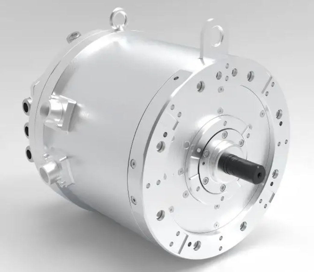
The machine considered here is a 1000 kW mining PMSM electric motor. The principal structural and electromagnetic parameters are summarized in Table 1. The complete assembly contains a large number of discrete parts whose explicit meshing would consume computational resources without adding thermal fidelity, so I reduce the model to two coupled domains: a simplified solid shell and a circumferential Z-shaped cooling circuit embedded inside that shell.
| Parameter | Value | Unit |
|---|---|---|
| Rated power | 1000 | kW |
| Overall length | 1158 | mm |
| Shell outer diameter | 1250 | mm |
| Shell inner diameter | 1120 | mm |
| Total mass | 7000 | kg |
| Active heat source area | 3.06 | m2 |
| Assumed electromagnetic loss fraction | 6 | % |
| Equivalent rated heat flux | 19607.83 | W/m2 |
The stator core, the rotor assembly and the permanent magnets cooperate to establish the working magnetic field, and they are simultaneously the dominant sources of loss. I therefore treat the shell inner wall region as a distributed heat source domain. Because the iron loss is assumed to be fully converted into heat, and because the eddy-current loss in the magnets is small for the operating frequency range of this PMSM electric motor, the volumetric source can be collapsed into a surface heat flux applied to the inner wall.
With the rated power PN and the loss fraction ηloss, the total thermal power delivered to the solid domain is
$$ Q = \eta_{\text{loss}} \, P_{\text{N}} = 0.06 \times 1000\ \text{kW} = 60\ \text{kW} $$
Distributing this thermal power over the active heat source area A gives the equivalent surface heat flux used as the thermal boundary condition:
$$ q = \frac{Q}{A} = \frac{60000}{3.06} \approx 19607.83\ \text{W}/\text{m}^2 $$
Equation (2) is the central link between the electromagnetic design of the PMSM electric motor and the thermal model. Its validity rests on the assumption that iron loss is entirely dissipated as heat and that the source is uniformly distributed over the wetted wall, an assumption that has been shown experimentally to reproduce measured winding and shell temperatures with acceptable accuracy in similar machines.
1.2 Governing Equations of the Coupled Model
The cooling water inside the Z-shaped circuit is modelled as an incompressible Newtonian fluid. Conservation of mass, momentum and energy in the fluid domain are written as
$$ \frac{\partial \rho}{\partial t} + \nabla \cdot \left( \rho \mathbf{u} \right) = 0 $$
$$ \frac{\partial \left( \rho \mathbf{u} \right)}{\partial t} + \nabla \cdot \left( \rho \mathbf{u} \mathbf{u} \right) = -\nabla p + \nabla \cdot \boldsymbol{\tau} + \rho \mathbf{g} $$
$$ \rho c_p \left( \frac{\partial T}{\partial t} + \mathbf{u} \cdot \nabla T \right) = \nabla \cdot \left( k \nabla T \right) + q_v $$
where ρ is the density, u the velocity vector, p the static pressure, τ the viscous stress tensor, cp the specific heat capacity, k the thermal conductivity and qv the volumetric heat source, which is zero in the fluid domain. In the solid domain only the energy equation survives, with u = 0:
$$ \rho_s c_{p,s} \frac{\partial T}{\partial t} = \nabla \cdot \left( k_s \nabla T \right) $$
The two domains are coupled at their common interface through the continuity of temperature and heat flux:
$$ T_s \big|_{\Gamma} = T_f \big|_{\Gamma}, \qquad -k_s \frac{\partial T_s}{\partial n}\bigg|_{\Gamma} = -k_f \frac{\partial T_f}{\partial n}\bigg|_{\Gamma} $$
The convective boundary condition applied on the outer shell surface, which faces the ventilated machine enclosure, is
$$ \dot{Q}_{\text{conv}} = h_{\text{air}} \, A_{\text{out}} \left( T_s – T_{\infty} \right) $$
with an air-side convective coefficient hair = 45 W/(m2·K), a value appropriate for the low-velocity air movement inside a flameproof enclosure.
The hydraulic behaviour of the cooling circuit is characterized by the Reynolds number and the frictional pressure loss. For a channel of hydraulic diameter Dh,
$$ Re = \frac{\rho v D_h}{\mu} $$
$$ \Delta p = f \frac{L}{D_h} \frac{\rho v^2}{2} + \sum \zeta_i \frac{\rho v^2}{2} $$
The first term on the right-hand side of Eq. (9) accounts for distributed friction along the straight portions of the Z-shaped channel, while the second term collects the local losses generated at each bend. The pump power required to sustain the flow is
$$ P_{\text{pump}} = \frac{\Delta p \, \dot{V}}{\eta_{\text{pump}}} $$
Equation (10) is the quantitative expression of the trade-off that governs water-cooling optimization: raising the flow rate V̇ reduces the shell temperature but increases the pressure loss, and because of Eq. (9) the pressure loss grows approximately with the square of the velocity while the pumping power grows with its cube. This cubic penalty is the reason why an unbounded increase in flow rate is never an acceptable design answer.
1.3 Mesh Generation and Independence Verification
The solid shell and the internal Z-shaped circuit are discretized with unstructured tetrahedral elements. The mesh independence study follows the behaviour of the outlet water temperature as the element size is refined. The results are condensed in Table 2.
| Element size [mm] | Outlet water temperature deviation [%] | Solution cost trend | Assessment |
|---|---|---|---|
| 6.0 | 0.85 | Low | Too coarse |
| 5.0 | 0.31 | Moderate | Marginal |
| 4.0 | 0.11 | Moderate | Acceptable |
| 3.0 | 0.02 | High | Selected |
| 2.0 | Reference | Very high | Cost prohibitive |
The outlet water temperature converges monotonically as the element size decreases, while the wall-clock cost of the computation rises steeply. Between 4 mm and 3 mm the change in the monitored quantity is already below 0.1 %, and refining further to 2 mm produces no meaningful change while more than doubling the solution time. I therefore select 3 mm as the working element size.
At this size the solid shell mesh contains 10,985,982 elements and the cooling circuit mesh contains 8,454,906 elements. The orthogonal quality of the generated mesh spans the range 0.321 to 1.0. A global smoothing pass with five iterations and an element quality threshold of 0.2 is applied, after which the mean skewness remains below 0.65 and the maximum skewness does not exceed 0.85. Locally distorted elements are additionally repaired with a threshold of 0.4. The combined evidence of the independence study and the quality metrics indicates that the mesh is adequate for a stable, accurate conjugate heat transfer solution of this PMSM electric motor.
1.4 Boundary Conditions and Solver Settings
Steady-state and transient simulations are performed in a commercial finite-volume environment using the thermal-fluid-solid coupling approach. For the steady-state parametric study the interface between the solid and fluid domains is set as a conservative heat transfer interface with a high-resolution advection scheme, a maximum of 100 outer iterations and an RMS residual target of 10−4. For the transient overload study the total physical time is 60 s, subdivided into 30 steps of 2 s each. The number of inner iterations per time step is capped at 20; the convergence history confirms that the early steps fully consume the 20 available iterations, whereas the middle and late steps converge within 1 to 3 iterations, and every step satisfies the residual criterion. The complete boundary condition set is listed in Table 3.
| Item | Setting |
|---|---|
| Solid domain material | Steel |
| Fluid domain material | Water |
| Ambient temperature | 298 K |
| Cooling water initial temperature | 298 K |
| Outlet relative pressure | 0 Pa |
| Rated inlet volumetric flow rate | 3 m3/h |
| Rated channel number | 7 |
| Heat source flux | 19607.83 W/m2 |
| Shell-to-air convective coefficient | 45 W/(m2·K) |
| Residual type and target | RMS, 10−4 |
| Transient total time | 60 s |
| Transient time step | 2 s |
| Maximum inner iterations | 20 |
The thermal source region boundary is extracted by sampling uniformly distributed points along its perimeter and collecting their coordinates, which guarantees that the flux is applied over exactly the intended area of 3.06 m2. Radiation is neglected, small chamfers and fillets on the shell and channels are removed during simplification, and the permanent magnet eddy-current loss is treated as negligible. These assumptions are consistent with the operating envelope of the PMSM electric motor considered here.
2. Baseline Flow and Temperature Fields
2.1 Flow Field Characteristics
Under the rated condition the pressure distribution along the cooling circuit is smooth and monotonic. The maximum static pressure occurs at the inlet and equals 1386.01 Pa. As the water travels circumferentially through the Z-shaped passage, the pressure falls at a nearly uniform rate and no localized high-pressure pocket forms anywhere in the circuit. The velocity field follows the same pattern. The maximum velocity, 1.17 m/s, is again found at the inlet, and the velocity decreases gradually along the flow path. The only regions of noticeably reduced velocity are the sharp bends, where a thin low-speed layer develops; these layers do not coalesce into a large stagnation zone, and the overall velocity distribution remains well balanced. A uniformly distributed velocity field is a prerequisite for a uniform convective coefficient on the channel wall, and thus for an even temperature field in the PMSM electric motor.
2.2 Temperature Field Characteristics
Under the rated condition the highest shell temperature is 348.63 K and the highest channel wall temperature is 344.38 K. Both maxima are located inside the heat source region. There is no large-area high-temperature cluster anywhere in the machine, which indicates that the Z-shaped circuit distributes the cooling capacity effectively around the circumference. The water temperature rises steadily along the flow direction, and the shell and channel temperature fields evolve in step with one another, confirming that the conjugate coupling is physically consistent. A mild axial imbalance is observed where portions of the shell and channel lie outside the active heat source region; this imbalance is a geometric consequence of the source distribution rather than a hydraulic deficiency.
3. Optimization of the Water-Cooling Parameters
Two parameters are optimized: the inlet volumetric flow rate and the number of parallel cooling channels. The flow rate governs the convective coefficient and the pumping penalty, while the channel number governs the wetted area and the hydraulic diameter. The two effects are examined sequentially so that the contribution of each can be isolated.
3.1 Influence of the Inlet Volumetric Flow Rate
Starting from the rated value of 3 m3/h, five additional flow rates are examined at intervals of 0.5 m3/h, giving a set of six cases: 2.0, 2.5, 3.0, 3.5, 4.0 and 4.5 m3/h. All other boundary conditions are held constant. The results are summarized in Table 4.
| Inlet flow rate [m3/h] | Maximum shell temperature trend | Maximum water pressure trend | Engineering assessment |
|---|---|---|---|
| 2.0 | Baseline, 367.95 K | Low | Insufficient cooling |
| 2.5 | Marked decrease | Gentle rise | Still below optimum |
| 3.0 | Continued decrease | Moderate | Selected balance point |
| 3.5 | 344.31 K, reduced by 23.64 K (6.87 %) relative to 2.0 | Onset of steep rise | Cooling nearly saturated |
| 4.0 | Essentially unchanged | Significant increase | Marginal benefit |
| 4.5 | Essentially unchanged | Sharp increase | Excessive pump consumption |
The maximum shell temperature decreases monotonically with increasing flow rate, and the cooling benefit is substantial at low flow rates. Raising the flow rate from 2.0 to 3.5 m3/h lowers the peak shell temperature from 367.95 K to 344.31 K, a reduction of 23.64 K, or 6.87 % on the absolute temperature scale. Beyond 3.5 m3/h the curve flattens and further increases in flow rate produce almost no additional cooling.
The hydraulic response is qualitatively opposite. The maximum water pressure rises steeply with flow rate, and the slope of the pressure curve itself increases, which is the direct signature of the quadratic friction term in Eq. (9). The two responses can be combined into a single trade-off function of the form
$$ \Phi \left( \dot{V} \right) = \frac{T_{\max} \left( \dot{V} \right) – T_{\text{ref}}}{T_{\text{ref}}} + \lambda \, \frac{P_{\text{pump}} \left( \dot{V} \right)}{P_{\text{ref}}} $$
where Tmax is the peak shell temperature, Ppump the pump power from Eq. (10), and λ a weighting coefficient that expresses how strongly the designer penalizes hydraulic consumption. The minimum of Φ identifies the flow rate at which cooling gain and hydraulic cost are balanced.
Plotting the maximum shell temperature and the maximum water pressure as functions of the flow rate on a common abscissa shows that the two curves intersect in the interval between 3.0 and 3.5 m3/h, at a value very close to 3.0 m3/h. This intersection is the point at which the PMSM electric motor achieves good heat removal without an excessive pumping penalty. Below 3.0 m3/h the shell temperature is too high and the thermal margin of the PMSM electric motor becomes inadequate; above 3.0 m3/h the temperature curve flattens while the pressure curve accelerates upward. I therefore fix the inlet volumetric flow rate at 3 m3/h for all subsequent analyses.
3.2 Influence of the Channel Number
With the flow rate fixed at 3 m3/h, the number of parallel channels in the Z-shaped circuit is varied from the rated value of seven through 8, 9, 10, 11 and 12. Increasing the channel number increases the total wetted perimeter, reduces the hydraulic diameter of each passage, and raises the local velocity for a given total flow rate. The results are collected in Table 5.
| Channel number | Maximum shell temperature trend | Maximum water pressure trend | Engineering assessment |
|---|---|---|---|
| 7 | Baseline, 348.63 K | Reference level | Rated configuration |
| 8 | Decreasing | Gentle rise | Improvement available |
| 9 | Decreasing | Gentle rise | Improvement available |
| 10 | 337.45 K, reduced by 11.18 K | Still moderate | Selected configuration |
| 11 | Reduction below 1 K | Steep rise | Saturated |
| 12 | Reduction below 1 K | Very steep rise | Uneconomical |
The peak shell temperature falls as the channel number rises. At ten channels the peak shell temperature reaches 337.45 K, which is 11.18 K lower than the 348.63 K obtained with the rated seven-channel configuration. Once the channel number exceeds ten, the additional temperature reduction is smaller than 1 K, meaning that the heat removal capability has effectively saturated. The marginal thermal return no longer justifies the added manufacturing complexity, so ten channels are selected.
The pressure behaviour reinforces this choice. The maximum water pressure increases with the channel number, because a larger channel count implies a smaller hydraulic diameter and a higher velocity for the same volumetric flow rate, and the friction loss depends on velocity through Eq. (9). When the channel number is below ten the pressure curve remains comparatively flat and its slope is stable. Above ten the pressure curve rises sharply. The coexistence of a saturated temperature response and an accelerating pressure response defines ten as the optimum.
3.3 Comparison of the Baseline and Optimized Configurations
Table 6 compares the rated condition computed with the original parameters and with the optimized parameters selected above.
| Quantity | Baseline (7 channels, 3 m3/h) | Optimized (10 channels, 3 m3/h) |
|---|---|---|
| Maximum shell temperature | 348.63 K | 337.45 K |
| Maximum channel wall temperature | 344.38 K | 333.07 K |
| Outlet water temperature | — | 310.66 K |
| Maximum inlet pressure | 1386.01 Pa | Higher, but within the pump budget |
The optimized configuration lowers the peak shell temperature of the PMSM electric motor by 11.18 K at the rated duty point without increasing the volumetric flow rate, so the pumping penalty is limited to the pressure rise associated with the narrower channels. This is the configuration carried forward into the overload reliability study.
4. Short-Time Overload Thermal Reliability
4.1 Definition of the Overload Duty
The applicable standard for flameproof permanent magnet variable-frequency mining motors requires that the machine sustain 1.5 times rated torque for at least one minute while remaining below the safe temperature limit. Because electromagnetic torque in a surface-mounted PMSM electric motor is proportional to the quadrature-axis current, the torque overload can be mapped onto a current overload:
$$ T_e = \frac{3}{2} \, p \, \lambda_m \, i_q \quad \Longrightarrow \quad \frac{T_{\text{over}}}{T_{\text{N}}} = \frac{i_{q,\text{over}}}{i_{q,\text{N}}} = 1.5 $$
Because the loss density scales approximately with the square of the current, the thermal load must be scaled accordingly:
$$ q_{\text{over}} = \left( 1.5 \right)^2 q_{\text{N}} = 2.25 \, q_{\text{N}} = 2.25 \times 19607.83 \approx 44117.6\ \text{W}/\text{m}^2 $$
This 2.25-fold multiplication of the rated heat flux is used as the equivalent thermal boundary condition for the transient simulation, which avoids the cost of a full electromagnetic-thermal co-simulation while preserving the correct magnitude of the thermal load. The initial condition for the transient is the converged steady-state field at the optimized rated duty point, and the transient is advanced for 60 s in 30 steps of 2 s.
4.2 Verification of the Time Step
A 2 s step could in principle smear the rapid temperature excursion that occurs immediately after the overload is applied, so a step independence check is performed. In the first case the calculation runs with a 2 s step and yields a peak shell temperature of 340.10 K after 2 s of overload. In the second case the total time is again 2 s but the step is reduced to 0.2 s. The refined calculation produces a smooth, gradually rising peak shell temperature curve with no abrupt jump, and the peak shell temperature at 2 s is 340.201 K. The relative difference between the two calculations is
$$ \varepsilon = \frac{\left| T_{0.2} – T_{2} \right|}{T_{0.2}} \times 100\% = \frac{\left| 340.201 – 340.10 \right|}{340.201} \times 100\% \approx 0.03\% $$
A relative error of 0.03 % is far inside the acceptable range, which confirms that a 2 s step resolves the early transient of this PMSM electric motor accurately and that the 30-step discretization is adequate.
4.3 Flow Field Under Overload
During the overload the hydraulic behaviour of the circuit changes only because the water properties change with temperature; the flow rate itself is held constant. The pressure falls progressively as the water travels one full circuit, and the maximum static pressure at the inlet is 1837.12 Pa. This value is modest and places only a light demand on the pump. The pressure gradient along the passage is stable, with no abrupt discontinuity.
The velocity distribution remains favourable because the Z-shaped circuit uses a comparatively small number of wide passages, so the flow is not strongly disturbed by the sharp bends. The overall hydraulic resistance is low and the flow field is stable. Local low-speed recirculation cells appear only in the immediate vicinity of the sharpest bends, and they do not merge into a continuous stagnant region. The practical consequence is that a stable convective boundary layer is maintained on the channel wall throughout the overload, which is the mechanism that guarantees spatial uniformity of cooling in the PMSM electric motor.
4.4 Temperature Field Under Overload
Analyzing the 30 stored time steps shows that the peak shell temperature occurs at the final instant, t = 60 s. At that moment the maximum shell temperature is 359.94 K and the maximum channel wall temperature is 351.51 K. Both maxima are concentrated on the inner wall of the shell, which is where the heat source is applied. Relative to the optimized rated condition, the overload produces a temperature rise of 22.49 K in the shell and 18.44 K in the channel wall, corresponding to average rates of 0.37 K/s and 0.31 K/s over the full 60 s interval.
The safety assessment is summarized in Table 7. The peak shell temperature of 359.94 K is far below the 423 K shell limit for mining motors, and it also lies inside the 363 K engineering design margin. It is well below the 393 K safe operating ceiling for the permanent magnets and the internal winding insulation. The temperature field remains uniform across the machine, with no extended high-temperature cluster, so the cooling architecture is compatible with the thermal demands of the mining duty.
| Criterion | Threshold [K] | Peak shell temperature at 60 s [K] | Margin [K] | Verdict |
|---|---|---|---|---|
| Shell limit for mining motors | 423 | 359.94 | 63.06 | Pass |
| Engineering design margin | 363 | 359.94 | 3.06 | Pass |
| Winding and magnet ceiling | 393 | 359.94 | 33.06 | Pass |
4.5 Transient Temperature Rise Curves
The evolution of the peak shell temperature and the outlet water temperature is divided into four intervals for interpretation. The initial state is the optimized rated condition, in which the shell temperature is 337.45 K and the outlet water temperature is 310.66 K. The instantaneous temperature rise rate in each interval is approximated by the finite difference
$$ \left. \frac{dT}{dt} \right|_{\text{avg}} \approx \frac{T \left( t_2 \right) – T \left( t_1 \right)}{t_2 – t_1} $$
Table 8 lists the interval-wise behaviour of both monitored quantities.
| Interval [s] | Shell temperature range [K] | Shell rise [K] | Shell average rate [K/s] | Outlet water range [K] | Water rise [K] | Water average rate [K/s] |
|---|---|---|---|---|---|---|
| 0–2 | 337.45 → 340.10 | 2.65 | 1.325 | 310.66 → 310.66+ | Small | Small |
| 0–20 | 337.45 → 348.48 | 11.03 | 0.55 | 310.66 → 312.49 | 1.83 | 0.09 |
| 20–40 | 348.48 → 355.09 | 6.61 | 0.33 | 312.49 → 314.07 | 1.58 | 0.08 |
| 40–60 | 355.09 → 359.94 | 4.85 | 0.24 | 314.07 → 315.57 | 1.50 | 0.075 |
In the first two seconds the shell temperature jumps from 337.45 K to 340.10 K, a rise of 2.65 K. This is the direct thermal signature of the sudden current step: the loss density in the PMSM electric motor increases by a factor of 2.25 almost instantaneously, while the thermal mass of the shell and the thermal capacitance of the coolant can only respond with a finite time constant.
During the first 20 s the shell temperature climbs from 337.45 K to 348.48 K, an increase of 11.03 K at an average rate of 0.55 K/s. This is the most aggressive phase of the overload transient. Between 20 s and 40 s the rise moderates to 6.61 K, and the average rate falls to 0.33 K/s. Between 40 s and 60 s the rise is only 4.85 K, with an average rate of 0.24 K/s. The progressive flattening of the curve demonstrates that the cooling circuit is removing an increasing fraction of the generated heat as the temperature difference between the shell and the coolant grows, which is exactly the behaviour predicted by the convective term in Eq. (7) and by the energy balance
$$ m_s c_{p,s} \frac{dT_s}{dt} = Q_{\text{gen}} – h A \left( T_s – T_w \right) – \dot{m} c_p \left( T_{\text{out}} – T_{\text{in}} \right) $$
At sufficiently long times the left-hand side of Eq. (15) tends to zero and the system approaches a new equilibrium in which the generated heat is fully balanced by convective removal.
The outlet water temperature follows the same qualitative pattern and confirms the interpretation. In the first 20 s it rises from 310.66 K to 312.49 K, an increase of 1.83 K at 0.09 K/s, indicating that the coolant is absorbing a large quantity of heat while the shell heats up rapidly. Between 20 s and 40 s the rise decreases to 1.58 K at 0.08 K/s, and between 40 s and 60 s it decreases further to 1.50 K at 0.075 K/s. The shell and the water warm in step with one another, which is the expected consequence of a well-coupled conjugate system.
Plotting the instantaneous temperature rise rate of both quantities as a function of overload duration shows that the highest values occur within the first two seconds, when the shell generates heat rapidly and the coolant extracts it at the highest local rate. Between 2 s and 30 s both rates fall substantially, and between 30 s and 60 s they settle at low and nearly constant values. The fact that the peak shell temperature at every instant within the 60 s window stays far below the 423 K limit is the decisive reliability result: the optimized water-cooling parameters of this PMSM electric motor are adequate for the required overload duty.
4.6 Consolidated Reliability Assessment
Table 9 consolidates the verification evidence gathered in this study.
| Verification item | Requirement | Result | Status |
|---|---|---|---|
| Overload torque capability | 1.5 times rated torque | Equivalent 2.25 times rated heat flux applied | Satisfied |
| Overload duration | Not less than 60 s | Simulated for the full 60 s | Satisfied |
| Peak shell temperature | Below 423 K | 359.94 K at 60 s | Satisfied |
| Peak channel wall temperature | Below 393 K | 351.51 K at 60 s | Satisfied |
| Outlet water stability | No abrupt fluctuation | Smooth rise of 1.50 K in the final interval | Satisfied |
| Time step adequacy | Relative error below 1 % | 0.03 % | Satisfied |
| Flow field uniformity | No extended stagnation | Local recirculation only at sharp bends | Satisfied |
| Pump demand | Within the auxiliary budget | Maximum inlet pressure 1837.12 Pa | Satisfied |
5. Engineering Implications for the Mining PMSM Electric Motor
The results carry several practical messages for the design of a high-power mining PMSM electric motor.
The first message concerns the diminishing return of increasing the volumetric flow rate. The pressure loss law in Eq. (9) makes the pumping power grow faster than the cooling benefit, so the optimum flow rate is not the maximum available value but the point where the two responses cross. For the machine studied here that point lies at approximately 3 m3/h.
The second message concerns the channel number. Adding channels increases the wetted area and the local velocity, but it simultaneously shrinks the hydraulic diameter and raises the friction loss. The heat transfer saturates once the thermal resistance of the solid path becomes comparable to the convective resistance, and beyond that point extra channels merely consume hydraulic head. Ten channels are found to be the saturation threshold for this shell geometry.
The third message concerns the overload transient itself. The temperature rise rate in the first two seconds is roughly a factor of five to six higher than the rate in the final 20 s interval. Any thermal protection strategy for a mining PMSM electric motor must therefore respond on a time scale of seconds, not minutes, if it is to prevent an overload from progressing into a thermal fault. The fact that the shell temperature remains 63 K below the limit even under a 2.25-fold thermal load reflects the generous thermal design margin achieved by the optimized cooling configuration.
The fourth message concerns the division between the solid and fluid contributions to overload protection. During the first 20 s the shell temperature rises quickly while the outlet water temperature rises only slightly, which means that the solid thermal capacitance is the dominant buffer in the early stage. During the final 20 s the two rates converge, indicating that the system has shifted to a convective-dominated regime. A designer aiming to extend the permissible overload duration would obtain the greatest benefit from increasing the convective capability rather than from adding solid mass.
6. Conclusions
I have constructed a thermal-fluid-solid coupled model of a 1000 kW mining PMSM electric motor, optimized its water-cooling parameters, and verified the thermal reliability of the optimized design under a short-time overload duty. The main conclusions are as follows.
Increasing the inlet volumetric flow rate improves heat removal appreciably, but the maximum water pressure rises sharply at the same time. A flow rate of 3 m3/h brings the cooling performance and the pump power consumption into relative balance for this PMSM electric motor. Raising the flow rate from 2.0 to 3.5 m3/h lowers the peak shell temperature from 367.95 K to 344.31 K, a reduction of 23.64 K or 6.87 %, but the curve becomes flat beyond 3.5 m3/h.
Increasing the number of parallel cooling channels also improves heat removal. With ten channels the peak shell temperature falls to 337.45 K, which is 11.18 K lower than the 348.63 K obtained with the rated seven-channel configuration. Once the channel number exceeds ten the additional temperature reduction is less than 1 K and the pressure curve rises steeply, so ten channels are identified as the saturation threshold.
Under a 1.5 times rated torque overload lasting 60 s, the temperature field of the optimized PMSM electric motor remains uniform with no large high-temperature region. The peak shell temperature reaches 359.94 K, which is far below the 423 K limit and satisfies the 363 K engineering design margin as well as the 393 K winding and magnet ceiling. The maximum inlet pressure is 1837.12 Pa, the flow field contains no extended stagnation zone, and the instantaneous peak shell temperature stays below the safety threshold at every instant within the 60 s window.
The average temperature rise rate of the peak shell temperature over the interval from 40 s to 60 s is 0.24 K/s, and the corresponding rate for the outlet water temperature is 0.075 K/s. Both rates are markedly lower than the values observed in the first 20 s, which confirms that the cooling circuit progressively takes over the heat removal duty and that the thermal transient stabilizes rather than diverging. The circumferential Z-shaped circuit combined with the optimized water-cooling parameters therefore provides reliable heat dissipation for the PMSM electric motor under short-time overload, and the design procedure reported here offers a transferable engineering reference for the thermal optimization of high-power mining drives.