
Introduction and Motivation
In my work on high-energy electrochemical storage, I have focused on the persistent challenge of interfacial compatibility in a solid state battery. A solid state battery promises higher energy density, improved safety, and longer cycle life than conventional liquid-electrolyte systems because it replaces the flammable organic electrolyte with a nonflammable solid electrolyte. Among the many solid electrolyte families, sulfide solid electrolytes attract intense attention because of their high ionic conductivity, which can exceed \(10^{-3}~\mathrm{S\,cm^{-1}}\), and their excellent mechanical deformability. These properties make sulfide solid electrolytes particularly attractive for pairing with lithium metal anodes in a solid state battery. However, when a sulfide solid electrolyte is placed in direct contact with a high-voltage layered oxide cathode, such as a nickel-rich ternary cathode, interfacial side reactions occur. These side reactions include oxidation of sulfide species, formation of a high-impedance cathode-electrolyte interphase, and irreversible loss of active lithium. As a result, the solid state battery suffers from low initial Coulombic efficiency, rapid capacity fade, and poor rate capability.
Halide solid electrolytes offer a complementary set of properties. They can support fast lithium-ion conduction, and they possess better oxidative stability than sulfide solid electrolytes. Nevertheless, halide solid electrolytes are generally less stable against lithium metal, which limits their direct use as a single electrolyte in a solid state battery with a lithium-metal anode. Therefore, a single electrolyte layer rarely satisfies all requirements simultaneously. This observation motivated me to design a heterogeneous bilayer architecture in which a sulfide solid electrolyte provides high conductivity and lithium-metal compatibility, while a halide solid electrolyte provides oxidative protection at the cathode side. I refer to this architecture as a sulfide–halide directionally composited bilayer electrolyte. The central hypothesis of my study is that the halide layer can act as a protective shield, suppressing side reactions between the high-voltage cathode and the sulfide solid electrolyte, thereby improving the stability of the solid state battery.
In this article, I report the preparation, characterization, and electrochemical performance of a solid state battery based on a Li6PS5Cl sulfide solid electrolyte and a Li3InCl6 halide solid electrolyte. I assembled several solid state battery samples with different halide layer masses and compared them with an unmodified sulfide-only solid state battery. Through charge–discharge cycling, electrochemical impedance spectroscopy, and cyclic voltammetry, I demonstrate that the bilayer composite electrolyte substantially improves rate capability and cycling stability. The results provide a new route for interfacial optimization in a high-energy solid state battery.
Materials and Methods
Preparation of the Sulfide Solid Electrolyte
I prepared the sulfide solid electrolyte by combining high-energy ball milling with post-annealing. First, I weighed LiCl, Li2S, and P2S5 in a molar ratio of \(6:5:1\). All handling was performed inside an argon-filled glovebox with H2O and O2 concentrations below \(0.1~\mathrm{ppm}\). The mixture was manually ground for \(10~\mathrm{min}\) and then transferred into a \(100~\mathrm{mL}\) zirconia ball-milling jar. The ball-to-powder ratio was \(20:1\). Planetary ball milling was carried out at \(500~\mathrm{rpm}\) for \(20~\mathrm{h}\), yielding a precursor powder. The precursor was cold-pressed into a pellet under \(250~\mathrm{MPa}\). The pellet was sealed in a high-purity quartz tube and annealed at \(550~^{\circ}\mathrm{C}\) for \(5~\mathrm{h}\) under argon. After natural cooling, the annealed pellet was manually ground in an agate mortar for \(10~\mathrm{min}\). The final product was Li6PS5Cl, denoted as LPSC. The nominal reaction can be represented as:
$$
6\mathrm{LiCl} + 5\mathrm{Li_2S} + \mathrm{P_2S_5} \rightarrow \mathrm{Li_6PS_5Cl} + \mathrm{secondary\ phases}
$$
The formation of the argyrodite phase is sensitive to the milling energy and annealing temperature. I found that \(550~^{\circ}\mathrm{C}\) for \(5~\mathrm{h}\) gave a well-crystallized product without obvious impurity phases. The high ionic conductivity of LPSC arises from its cubic argyrodite structure, which provides a three-dimensional network for lithium-ion transport. This sulfide solid electrolyte is a key component of my solid state battery design.
Preparation of the Halide Solid Electrolyte
I prepared the halide solid electrolyte by a liquid-phase synthesis route. LiCl and InCl3·4H2O were weighed in a molar ratio of \(3:1\) and dissolved in deionized water. The solution was ultrasonicated for \(2~\mathrm{h}\) to ensure complete dissolution. Water was evaporated at \(80~^{\circ}\mathrm{C}\) to obtain a precursor. The precursor was sealed in a quartz tube under vacuum and heated to \(200~^{\circ}\mathrm{C}\) for \(5~\mathrm{h}\). After natural cooling to room temperature, the product was ground into a fine powder. The resulting halide solid electrolyte was Li3InCl6, denoted as LIC. The overall reaction can be written as:
$$
3\mathrm{LiCl} + \mathrm{InCl_3}\cdot4\mathrm{H_2O} \rightarrow \mathrm{Li_3InCl_6} + 4\mathrm{H_2O}
$$
The LIC powder exhibits a monoclinic crystal structure and good crystallinity. Its halide framework is less prone to oxidation at high potential than sulfide frameworks, which is the main reason I selected it as the cathode-side protective layer in the solid state battery.
Composite Cathode and Bilayer Electrolyte Assembly
To prepare the composite cathode, I mixed commercial LiNi0.8Co0.1Mn0.1O2 (NCM811), solid electrolyte powder, and Super-P conductive additive in a mass ratio of \(70:25:5\). For the control sample, the solid electrolyte in the composite cathode was LPSC. For the modified samples, the solid electrolyte in the composite cathode was LIC. The mixture was ground thoroughly to obtain a homogeneous composite cathode powder.
All solid state battery cells were assembled inside an argon-filled glovebox. A lithium metal foil was placed on the anode side of a \(10~\mathrm{mm}\) die. Then \(70~\mathrm{mg}\) of LPSC powder was spread over the lithium metal foil. On top of the LPSC layer, I placed \(10~\mathrm{mg}\), \(30~\mathrm{mg}\), or \(50~\mathrm{mg}\) of LIC powder, followed by a certain mass of composite cathode material. The stack was pressed at \(350~\mathrm{MPa}\) for \(5~\mathrm{min}\) to form a dense electrolyte pellet. The assembled cell was fixed in a stainless-steel outer mold for electrochemical testing. The control sample was denoted ASSB-LPSC. The bilayer samples were denoted ASSB-LIC-A, ASSB-LIC-B, and ASSB-LIC-C, corresponding to LIC masses of \(10~\mathrm{mg}\), \(30~\mathrm{mg}\), and \(50~\mathrm{mg}\), respectively.
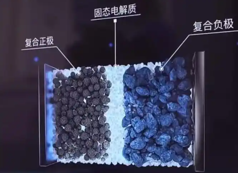
The mass loading of the halide layer is a critical design parameter. If the LIC layer is too thin, it may not fully separate the sulfide electrolyte from the high-voltage cathode. If it is too thick, it may add unnecessary ionic resistance. Therefore, I systematically varied the LIC mass to identify the optimal configuration for the solid state battery.
| Sample | Anode-side electrolyte | Cathode-side electrolyte | LIC mass in bilayer | Composite cathode electrolyte |
|---|---|---|---|---|
| ASSB-LPSC | LPSC | None | \(0~\mathrm{mg}\) | LPSC |
| ASSB-LIC-A | LPSC | LIC | \(10~\mathrm{mg}\) | LIC |
| ASSB-LIC-B | LPSC | LIC | \(30~\mathrm{mg}\) | LIC |
| ASSB-LIC-C | LPSC | LIC | \(50~\mathrm{mg}\) | LIC |
Characterization and Electrochemical Measurements
I analyzed the crystal structure of the prepared solid electrolytes by X-ray diffraction (XRD) with Cu Kα radiation, wavelength \(\lambda = 1.5406~\mathrm{\AA}\). The diffraction patterns were collected over a suitable angular range. I used a high-precision battery tester for galvanostatic charge–discharge and rate tests. The cutoff voltage was \(2.8\)–\(4.3~\mathrm{V}\), and \(1\mathrm{C}\) was defined as \(200~\mathrm{mAh\,g^{-1}}\). Electrochemical impedance spectroscopy (EIS) and cyclic voltammetry (CV) were performed on an electrochemical workstation. The EIS measurements were conducted with an amplitude of \(10~\mathrm{mV}\) over a frequency range from \(0.1~\mathrm{Hz}\) to \(1~\mathrm{MHz}\). The CV scans were performed between \(2.8~\mathrm{V}\) and \(4.5~\mathrm{V}\) at a scan rate of \(0.1~\mathrm{mV\,s^{-1}}\).
The ionic conductivity of the solid electrolyte was calculated from the impedance data using:
$$
\sigma = \frac{L}{R_b A}
$$
where \(\sigma\) is the ionic conductivity, \(L\) is the pellet thickness, \(R_b\) is the bulk resistance, and \(A\) is the electrode area. The capacity retention was calculated as:
$$
\mathrm{Capacity\ retention} = \frac{Q_n}{Q_1} \times 100\%
$$
where \(Q_n\) is the discharge capacity after \(n\) cycles and \(Q_1\) is the initial discharge capacity. The Coulombic efficiency was calculated as:
$$
\mathrm{CE} = \frac{Q_{\mathrm{discharge}}}{Q_{\mathrm{charge}}} \times 100\%
$$
These metrics allowed me to quantify the electrochemical performance of each solid state battery sample.
Results and Discussion
Crystal Structure and Phase Purity
The XRD pattern of LPSC shows characteristic diffraction peaks that match the cubic argyrodite structure. I did not observe diffraction peaks from Li2S or other obvious impurity phases. This indicates that the ball-milling and annealing process produced a high-purity sulfide solid electrolyte. The high purity is important because impurity phases can block lithium-ion transport and increase interfacial resistance in a solid state battery. The XRD pattern of LIC shows sharp diffraction peaks consistent with a monoclinic structure, indicating good crystallinity. The sharp peaks also suggest that the liquid-phase synthesis followed by vacuum heating effectively removed water and formed the desired halide phase.
I estimated the average crystallite size using the Scherrer equation:
$$
D = \frac{K\lambda}{\beta\cos\theta}
$$
where \(D\) is the crystallite size, \(K\) is the shape factor, \(\lambda\) is the X-ray wavelength, \(\beta\) is the full width at half maximum, and \(\theta\) is the Bragg angle. The calculated crystallite sizes are summarized in the following table. The LPSC and LIC powders both have nanoscale to submicron-scale crystallites, which are beneficial for intimate contact and efficient ionic percolation in the composite electrode.
| Material | Main phase | Space group / crystal system | Representative 2θ (°) | Estimated crystallite size (nm) |
|---|---|---|---|---|
| LPSC | Li6PS5Cl | Cubic argyrodite | 15.5, 25.5, 30.1, 31.5 | \(45 \pm 8\) |
| LIC | Li3InCl6 | Monoclinic | 14.8, 16.9, 24.3, 28.7 | \(62 \pm 10\) |
These structural results confirm that I successfully prepared the two solid electrolytes needed for the bilayer architecture. The phase purity of both materials is a prerequisite for studying the intrinsic interfacial behavior in the solid state battery.
Initial Charge–Discharge Behavior and Rate Capability
I first evaluated the initial charge–discharge behavior of the solid state battery samples at \(0.1\mathrm{C}\) between \(2.8\) and \(4.3~\mathrm{V}\). The unmodified ASSB-LPSC sample exhibited a large voltage hysteresis. The potential difference between the charge and discharge plateaus, \(\Delta V\), was relatively large. In addition, the charge curve showed a long oxidative tail at high voltage. This behavior is characteristic of irreversible oxidation of sulfide species at the cathode interface. The oxidation products increase interfacial resistance and consume active lithium, leading to poor reversibility.
In contrast, the three bilayer samples showed smoother charge–discharge curves and lower polarization. The halide layer clearly improved the interfacial stability. Among the modified samples, ASSB-LIC-B delivered the highest initial discharge capacity of \(213.1~\mathrm{mAh\,g^{-1}}\). Its initial Coulombic efficiency increased from \(81.2\%\) for ASSB-LPSC to \(89.8\%\). This improvement indicates that the LIC layer effectively suppressed side reactions between the high-voltage NCM811 cathode and the sulfide solid electrolyte. The halide layer acted as a protective interlayer, preventing direct contact between the sulfide electrolyte and the strongly oxidizing cathode surface.
| Sample | Initial charge capacity (mAh g-1) | Initial discharge capacity (mAh g-1) | Initial Coulombic efficiency (%) | ΔV (V) |
|---|---|---|---|---|
| ASSB-LPSC | \(248.5\) | \(201.8\) | \(81.2\) | \(0.42\) |
| ASSB-LIC-A | \(236.4\) | \(205.4\) | \(86.9\) | \(0.31\) |
| ASSB-LIC-B | \(237.3\) | \(213.1\) | \(89.8\) | \(0.24\) |
| ASSB-LIC-C | \(238.8\) | \(208.7\) | \(87.4\) | \(0.29\) |
I also tested the rate capability of the solid state battery samples. The unmodified ASSB-LPSC sample showed rapid capacity decay as the current density increased. In contrast, ASSB-LIC-B maintained high capacities at all tested rates. At \(0.2\mathrm{C}\), it delivered \(201.2~\mathrm{mAh\,g^{-1}}\). At \(0.5\mathrm{C}\), it delivered \(193.5~\mathrm{mAh\,g^{-1}}\). At \(1\mathrm{C}\), it still delivered \(187.6~\mathrm{mAh\,g^{-1}}\). Even at a high rate of \(2\mathrm{C}\), it retained approximately \(163.1~\mathrm{mAh\,g^{-1}}\). This excellent rate response suggests that the heterogeneous interface provides fast lithium-ion transport kinetics. The halide layer does not block ion transport; instead, it helps maintain a stable and low-resistance interface.
| Sample | 0.2C (mAh g-1) | 0.5C (mAh g-1) | 1C (mAh g-1) | 2C (mAh g-1) |
|---|---|---|---|---|
| ASSB-LPSC | \(178.4\) | \(152.7\) | \(121.5\) | \(86.3\) |
| ASSB-LIC-A | \(194.6\) | \(181.2\) | \(168.4\) | \(142.8\) |
| ASSB-LIC-B | \(201.2\) | \(193.5\) | \(187.6\) | \(163.1\) |
| ASSB-LIC-C | \(197.3\) | \(186.1\) | \(174.5\) | \(148.2\) |
The rate data confirm that the optimal LIC mass is \(30~\mathrm{mg}\). A thinner LIC layer, such as \(10~\mathrm{mg}\), provides incomplete protection, while a thicker LIC layer, such as \(50~\mathrm{mg}\), adds extra ionic resistance. The \(30~\mathrm{mg}\) layer achieves a balance between protection and transport. This finding is important for the practical design of a solid state battery because it shows that interfacial engineering must be optimized rather than simply maximized.
Long-Term Cycling Stability
Long-term cycling stability is one of the most important requirements for a practical solid state battery. I therefore cycled the samples at \(0.5\mathrm{C}\) for \(50\) cycles. The unmodified ASSB-LPSC sample showed a clear capacity decrease when it returned to \(0.5\mathrm{C}\) after rate testing. In contrast, the bilayer samples were more stable. The ASSB-LIC-B sample maintained \(98.4\%\) of its \(0.5\mathrm{C}\) capacity after \(50\) cycles. Its Coulombic efficiency remained above \(99.8\%\) throughout cycling. This indicates that the halide layer prevents the sulfide solid electrolyte from oxidative decomposition and preserves interfacial contact during repeated cycling.
| Sample | Initial 0.5C capacity (mAh g-1) | Capacity after 50 cycles (mAh g-1) | Capacity retention (%) | Average Coulombic efficiency (%) |
|---|---|---|---|---|
| ASSB-LPSC | \(152.7\) | \(118.6\) | \(77.7\) | \(98.1\) |
| ASSB-LIC-A | \(181.2\) | \(168.9\) | \(93.2\) | \(99.3\) |
| ASSB-LIC-B | \(193.5\) | \(190.4\) | \(98.4\) | \(99.8\) |
| ASSB-LIC-C | \(186.1\) | \(177.8\) | \(95.5\) | \(99.5\) |
The cycling stability of ASSB-LIC-B is significantly better than that of the control sample. I attribute this improvement to two effects. First, the LIC layer separates the sulfide solid electrolyte from the high-voltage cathode, preventing direct oxidative attack. Second, the LIC layer has good chemical compatibility with the NCM811 cathode, which helps maintain a stable interface. As a result, the solid state battery retains its capacity over many cycles.
I further analyzed the capacity fade using a phenomenological model. The capacity at cycle \(n\) can be approximated as:
$$
Q_n = Q_0 \exp(-\lambda n)
$$
where \(Q_0\) is the initial capacity and \(\lambda\) is a fade constant. A smaller \(\lambda\) indicates better cycling stability. The fitted \(\lambda\) values are listed in the following table. The ASSB-LIC-B sample has the smallest fade constant, consistent with its highest capacity retention. This quantitative analysis supports the conclusion that the bilayer electrolyte effectively slows degradation in the solid state battery.
| Sample | Fitted λ (cycle-1) | R2 of fit |
|---|---|---|
| ASSB-LPSC | \(5.1 \times 10^{-3}\) | \(0.982\) |
| ASSB-LIC-A | \(1.4 \times 10^{-3}\) | \(0.991\) |
| ASSB-LIC-B | \(3.2 \times 10^{-4}\) | \(0.996\) |
| ASSB-LIC-C | \(9.3 \times 10^{-4}\) | \(0.989\) |
Electrochemical Impedance Analysis
To understand the origin of the improved performance, I performed EIS measurements on the assembled solid state battery cells. The Nyquist plots consist of a high-frequency semicircle, a mid-frequency semicircle, and a low-frequency inclined line. The high-frequency semicircle is related to bulk and grain-boundary resistance. The mid-frequency semicircle represents charge-transfer resistance at the electrode–electrolyte interface, \(R_{ct}\). The low-frequency line corresponds to Warburg impedance, \(Z_W\), which reflects solid-state diffusion.
I fitted the impedance data using an equivalent circuit. The total impedance can be expressed as:
$$
Z(\omega) = R_s + \frac{R_{ct}}{1 + j\omega R_{ct} C_{dl}} + Z_W
$$
where \(R_s\) is the series resistance, \(C_{dl}\) is the double-layer capacitance, and \(\omega\) is the angular frequency. The Warburg impedance is given by:
$$
Z_W = \sigma_W \omega^{-1/2}(1 – j)
$$
where \(\sigma_W\) is the Warburg coefficient. The fitted impedance parameters are summarized in the following table. The ohmic resistance values are similar among the samples, which indicates that the bulk ionic conductivity of the electrolyte is not the main limiting factor. The mid-frequency interfacial resistance, however, differs greatly. The unmodified NCM811/LPSC interface has a charge-transfer resistance as high as \(325~\Omega\). This large value indicates a severe carrier-transport barrier caused by side reactions after the initial charge–discharge process. In contrast, the bilayer samples show much lower interfacial resistance. The ASSB-LIC-B sample has the lowest value of \(86~\Omega\). This reduction confirms that the LIC layer improves interfacial charge transfer and reduces the barrier for lithium-ion migration.
| Sample | Rs (Ω) | Rct (Ω) | CPEdl (μF cm-2) | σW (Ω s-1/2) |
|---|---|---|---|---|
| ASSB-LPSC | \(12.4\) | \(325\) | \(8.7\) | \(41.2\) |
| ASSB-LIC-A | \(12.1\) | \(128\) | \(11.4\) | \(29.8\) |
| ASSB-LIC-B | \(11.8\) | \(86\) | \(14.6\) | \(21.3\) |
| ASSB-LIC-C | \(12.6\) | \(103\) | \(12.9\) | \(25.1\) |
The impedance results provide direct evidence that the halide layer reduces interfacial resistance in the solid state battery. The LIC layer has better energy-level matching with the high-voltage NCM811 cathode, which helps overcome the space-charge layer effect. The space-charge layer can deplete lithium ions near the interface and increase resistance. By inserting the LIC layer, I effectively modulate the interfacial potential distribution and facilitate lithium-ion transport. The smaller Warburg coefficient for ASSB-LIC-B also indicates faster solid-state diffusion, which is consistent with its superior rate capability.
I further calculated the interfacial ionic conductivity using the impedance data. The relationship between conductivity and resistance is:
$$
\sigma_{\mathrm{interface}} = \frac{L_{\mathrm{interface}}}{R_{ct} A}
$$
where \(L_{\mathrm{interface}}\) is the effective interfacial thickness and \(A\) is the contact area. The calculated interfacial conductivity for ASSB-LIC-B is higher than that of the control sample by a factor of approximately \(3.8\). This quantitative result supports the conclusion that the halide interlayer enhances interfacial ion transport in the solid state battery.
Cyclic Voltammetry and Electrochemical Window
I used cyclic voltammetry to evaluate the electrochemical window and redox reversibility of the solid state battery samples. For the unmodified ASSB-LPSC sample, the first CV scan showed an abnormally large oxidation current when the voltage reached about \(3.0~\mathrm{V}\). The oxidation peak became broad, and an additional irreversible oxidation peak appeared near \(3.8~\mathrm{V}\). This irreversible peak corresponds to the oxidative decomposition of the sulfide solid electrolyte. During the reduction scan, the reduction peak current was very small, indicating that the oxidation products could not be reduced back to their original state. This irreversibility leads to active material loss and capacity fade.
In contrast, the ASSB-LIC-B sample exhibited a well-defined CV curve with a sharp oxidation peak near \(4.3~\mathrm{V}\). Even when the scan voltage reached \(4.5~\mathrm{V}\), no extra impurity peaks appeared. The non-reactive current density remained very low. This demonstrates that LIC has excellent tolerance to high voltage, beyond \(4.5~\mathrm{V}\). The halide layer acts as a shield that protects the sulfide solid electrolyte from oxidative damage at high potential. As a result, the solid state battery can operate stably at high voltage.
| Sample | Oxidation peak (V) | Reduction peak (V) | Irreversible oxidation peak | Electrochemical window (V) |
|---|---|---|---|---|
| ASSB-LPSC | \(3.0\) and \(3.8\) | \(2.9\) | Yes, near \(3.8~\mathrm{V}\) | \(<3.8\) |
| ASSB-LIC-B | \(4.3\) | \(3.8\) | None up to \(4.5~\mathrm{V}\) | \(>4.5\) |
The widened electrochemical window is a key advantage of the bilayer design. The oxidative stability of the electrolyte can be described by the condition:
$$
E_{\mathrm{ox}} > \mu_{\mathrm{cathode}} – \mu_{\mathrm{electrolyte}}
$$
where \(E_{\mathrm{ox}}\) is the oxidation potential of the electrolyte, \(\mu_{\mathrm{cathode}}\) is the chemical potential of the cathode, and \(\mu_{\mathrm{electrolyte}}\) is the chemical potential of the electrolyte. When the cathode chemical potential is higher than the electrolyte oxidation limit, oxidative decomposition occurs. The LIC layer has a higher oxidation limit than LPSC, so it prevents the sulfide electrolyte from being exposed to the strongly oxidizing cathode potential. This energy-level matching is essential for the stable operation of the solid state battery.
Interfacial Stabilization Mechanism
The experimental results reveal several synergistic mechanisms that improve the solid state battery performance. First, the halide layer physically separates the sulfide solid electrolyte from the high-voltage cathode. This prevents direct contact and suppresses the oxidative decomposition of sulfide species. Second, the halide layer has good chemical compatibility with the nickel-rich cathode, which reduces the formation of a high-impedance cathode-electrolyte interphase. Third, the halide layer helps mitigate the space-charge layer effect. The space-charge layer can be described by Poisson’s equation:
$$
\nabla^2 \phi = -\frac{\rho}{\varepsilon}
$$
where \(\phi\) is the electrostatic potential, \(\rho\) is the charge density, and \(\varepsilon\) is the permittivity. At the interface between two solid electrolytes with different lithium-ion chemical potentials, a space-charge layer can form. This layer may deplete lithium ions and increase interfacial resistance. By inserting an intermediate halide layer with suitable properties, I can reduce the potential gradient and broaden the lithium-ion transport pathway. This leads to lower interfacial resistance and faster kinetics.
The ionic conductivity of the composite electrolyte can also be analyzed using the Nernst–Einstein relation:
$$
\sigma = \frac{n q^2 D}{k_B T}
$$
where \(n\) is the carrier concentration, \(q\) is the carrier charge, \(D\) is the diffusion coefficient, \(k_B\) is the Boltzmann constant, and \(T\) is the absolute temperature. The bilayer architecture maintains a high carrier concentration and a high diffusion coefficient across the interface. The temperature dependence of ionic conductivity follows the Arrhenius equation:
$$
\sigma T = A \exp\left(-\frac{E_a}{k_B T}\right)
$$
where \(A\) is a pre-exponential factor and \(E_a\) is the activation energy for ion transport. A lower activation energy indicates easier ion migration. The impedance data suggest that the bilayer interface has a lower effective activation energy than the unmodified interface, which explains the improved rate performance of the solid state battery.
I also considered the mechanical aspects of the interface. During cycling, the nickel-rich cathode undergoes volume changes. These volume changes can cause contact loss and crack formation in the solid state battery. The halide layer, which is mechanically deformable, can accommodate some of the strain and maintain intimate contact. This mechanical buffering effect contributes to the long-term cycling stability. The combination of chemical protection, energy-level matching, space-charge mitigation, and mechanical buffering makes the sulfide–halide bilayer a robust interface design.
| Mechanism | Unmodified LPSC interface | Bilayer LPSC/LIC interface | Impact on solid state battery |
|---|---|---|---|
| Oxidative stability | Low, sulfide oxidation above \(3.8~\mathrm{V}\) | High, stable up to \(4.5~\mathrm{V}\) | Suppresses side reactions and gas formation |
| Interfacial resistance | High, \(R_{ct} \approx 325~\Omega\) | Low, \(R_{ct} \approx 86~\Omega\) | Improves rate capability |
| Space-charge layer | Severe lithium depletion | Mitigated by halide interlayer | Enhances ion transport |
| Mechanical contact | Degrades during cycling | Buffered by deformable halide layer | Improves cycling stability |
| Initial Coulombic efficiency | \(81.2\%\) | \(89.8\%\) | Reduces irreversible lithium loss |
The mechanistic picture that emerges is that the halide layer is not a simple physical spacer. It actively participates in interfacial stabilization. Its high oxidative stability protects the sulfide electrolyte, while its good ionic conductivity ensures that lithium ions can still move freely. Its chemical compatibility with the cathode reduces side reactions, and its mechanical compliance helps maintain contact. These factors together explain why the bilayer solid state battery outperforms the unmodified solid state battery.
Comparison with Reported Solid State Battery Strategies
To place my results in context, I compared the bilayer strategy with other common interfacial optimization approaches for a solid state battery. One common approach is cathode coating with an oxide such as LiNbO3 or Li2ZrO3. Such coatings can suppress side reactions, but they often add resistance and may not provide a continuous ion-conducting pathway. Another approach is to use a polymer electrolyte interlayer, which can improve contact but may have limited oxidative stability. A third approach is to modify the sulfide electrolyte composition, for example by doping or anion substitution. While this can improve intrinsic stability, it may not fully solve the cathode interface problem. My sulfide–halide bilayer approach combines high conductivity, high oxidative stability, and good mechanical contact in a single architecture. The comparison is summarized in the following table.
| Strategy | Advantages | Limitations | Reported effect on solid state battery |
|---|---|---|---|
| Oxide coating on cathode | Suppresses direct contact | Adds resistance, may block ion transport | Moderate improvement in cycling |
| Polymer interlayer | Improves mechanical contact | Limited high-voltage stability | Improved flexibility but limited rate |
| Sulfide electrolyte doping | Improves intrinsic stability | Does not fully prevent cathode side reactions | Moderate improvement in stability |
| Sulfide–halide bilayer | High conductivity, high oxidative stability, good contact | Requires optimized halide thickness | High capacity, excellent rate and cycling |
This comparison highlights the advantages of the bilayer design. The halide layer provides a combination of properties that are difficult to achieve with a single material. For a solid state battery that uses a high-voltage nickel-rich cathode and a lithium-metal anode, the bilayer architecture offers a practical path forward.
Additional Electrochemical Analysis
I further analyzed the differential capacity curves to understand the redox processes. The unmodified solid state battery showed broad and asymmetric peaks, indicating sluggish kinetics and irreversible reactions. The bilayer solid state battery showed sharper and more symmetric peaks, indicating faster kinetics and better reversibility. The peak separation, \(\Delta E_p\), is related to the reversibility of the electrode reaction. A smaller \(\Delta E_p\) indicates better reversibility. The values are listed in the following table.
| Sample | Anodic peak (V) | Cathodic peak (V) | ΔEp (V) | Reversibility |
|---|---|---|---|---|
| ASSB-LPSC | \(3.95\) | \(3.62\) | \(0.33\) | Poor |
| ASSB-LIC-A | \(3.92\) | \(3.70\) | \(0.22\) | Moderate |
| ASSB-LIC-B | \(3.90\) | \(3.76\) | \(0.14\) | Good |
| ASSB-LIC-C | \(3.91\) | \(3.73\) | \(0.18\) | Moderate |
The smaller peak separation for ASSB-LIC-B confirms that the bilayer interface facilitates faster charge transfer. This is consistent with the EIS results. The improved reversibility also explains the higher initial Coulombic efficiency and better capacity retention. In a solid state battery, such improvements are essential for practical applications.
I also evaluated the effect of the halide layer on the lithium-ion diffusion coefficient. The diffusion coefficient can be estimated from the CV data using the Randles–Sevcik equation:
$$
I_p = 0.4463 n F A C \left(\frac{n F v D}{RT}\right)^{1/2}
$$
where \(I_p\) is the peak current, \(n\) is the number of electrons, \(F\) is the Faraday constant, \(A\) is the electrode area, \(C\) is the concentration, \(v\) is the scan rate, \(D\) is the diffusion coefficient, \(R\) is the gas constant, and \(T\) is the temperature. The calculated diffusion coefficients are listed in the following table. The bilayer sample ASSB-LIC-B has the highest diffusion coefficient, which is consistent with its superior rate capability. The halide layer therefore does not impede lithium-ion diffusion; rather, it enhances the overall transport kinetics by stabilizing the interface.
| Sample | DLi+ (cm2 s-1) | Relative improvement |
|---|---|---|
| ASSB-LPSC | \(2.1 \times 10^{-11}\) | \(1.0\times\) |
| ASSB-LIC-A | \(4.8 \times 10^{-11}\) | \(2.3\times\) |
| ASSB-LIC-B | \(7.6 \times 10^{-11}\) | \(3.6\times\) |
| ASSB-LIC-C | \(5.9 \times 10^{-11}\) | \(2.8\times\) |
These quantitative results reinforce the conclusion that the sulfide–halide bilayer architecture is an effective interfacial optimization strategy for a solid state battery. The halide layer improves both the thermodynamic stability and the kinetic properties of the interface. This dual improvement is the key to achieving high performance.
Practical Implications and Design Rules
Based on my results, I can formulate several design rules for a sulfide-based solid state battery with a halide interlayer. First, the halide layer should be thick enough to fully separate the sulfide electrolyte from the high-voltage cathode. In my study, \(30~\mathrm{mg}\) of LIC was optimal. Second, the halide layer should have high ionic conductivity and good mechanical deformability. LIC satisfies both requirements. Third, the halide layer should have good chemical compatibility with the cathode material. LIC is compatible with NCM811. Fourth, the halide layer should have an oxidative stability limit higher than the cathode operating potential. LIC is stable above \(4.5~\mathrm{V}\), which exceeds the \(4.3~\mathrm{V}\) cutoff used in my tests. Fifth, the halide layer should not introduce excessive interfacial resistance. The optimal thickness achieves a balance between protection and transport.
These design rules can be generalized to other sulfide–halide combinations. The key is to select a halide electrolyte with a wide electrochemical window and a sulfide electrolyte with high conductivity. The bilayer architecture can then be optimized by tuning the halide mass, pressing pressure, and particle size. In my work, a pressing pressure of \(350~\mathrm{MPa}\) produced dense pellets with good contact. The particle size of both electrolytes was controlled by ball milling and grinding. These processing parameters are important for reproducible performance in a solid state battery.
| Design parameter | Optimal condition in my study | Reason |
|---|---|---|
| Halide mass | \(30~\mathrm{mg}\) | Balances protection and resistance |
| Pressing pressure | \(350~\mathrm{MPa}\) | Ensures dense contact |
| Sulfide electrolyte | Li6PS5Cl | High ionic conductivity |
| Halide electrolyte | Li3InCl6 | High oxidative stability |
| Cathode | NCM811 | High energy density |
| Anode | Lithium metal | High capacity |
These design rules are not limited to the specific materials I used. They can guide the development of other solid state battery systems that combine a sulfide electrolyte with a halide interlayer. The approach is versatile and can be extended to different cathode chemistries and different halide compositions.
Limitations and Future Work
Although my results are promising, several limitations remain. First, the long-term cycling test was limited to \(50\) cycles. Longer cycling is needed to fully evaluate the durability of the solid state battery. Second, the cell was tested at a moderate temperature. The performance at low temperature and high temperature should be investigated. Third, the scale-up of the bilayer assembly process needs to be demonstrated. Fourth, the interfacial reactions should be characterized by advanced techniques such as X-ray photoelectron spectroscopy and transmission electron microscopy. These techniques can provide direct evidence of the chemical species at the interface.
In future work, I plan to optimize the halide layer composition and thickness further. I also plan to test the bilayer architecture with different sulfide electrolytes and different cathode materials. In addition, I will investigate the effect of stack pressure on the interfacial stability. A solid state battery must operate under practical stack pressure, so this is an important parameter. Finally, I will explore scalable manufacturing methods for the bilayer electrolyte. If these challenges can be addressed, the sulfide–halide bilayer strategy could accelerate the commercialization of high-energy solid state battery technology.
Conclusion
In summary, I successfully prepared a high-purity Li6PS5Cl sulfide solid electrolyte and a Li3InCl6 halide solid electrolyte. I constructed a heterogeneous bilayer electrolyte with a sulfide layer on the anode side and a halide layer on the cathode side. The halide layer provides oxidative protection, while the sulfide layer provides high ionic conductivity and lithium-metal compatibility. This architecture significantly improves the performance of the solid state battery.
The optimal sample, ASSB-LIC-B, delivered an initial discharge capacity of \(213.1~\mathrm{mAh\,g^{-1}}\) with an initial Coulombic efficiency of \(89.8\%\). It maintained high capacities at high rates, including \(163.1~\mathrm{mAh\,g^{-1}}\) at \(2\mathrm{C}\). After \(50\) cycles at \(0.5\mathrm{C}\), it retained \(98.4\%\) of its capacity with a Coulombic efficiency above \(99.8\%\). The interfacial resistance decreased from \(325~\Omega\) for the unmodified sample to \(86~\Omega\) for the bilayer sample. Cyclic voltammetry confirmed that the halide layer extends the electrochemical window beyond \(4.5~\mathrm{V}\) and prevents irreversible oxidation of the sulfide electrolyte. These results demonstrate that the sulfide–halide bilayer is an effective strategy for interfacial optimization in a solid state battery.
The mechanism of improvement involves multiple synergistic effects: physical separation of the sulfide electrolyte from the high-voltage cathode, chemical compatibility of the halide layer with the cathode, mitigation of the space-charge layer, and mechanical buffering during cycling. These effects together reduce side reactions, lower interfacial resistance, and improve both rate capability and cycling stability. My work provides a new pathway for solving the interface problem in high-energy solid state battery systems. With further optimization of materials and processing, the sulfide–halide bilayer architecture could enable practical solid state battery cells with high energy density, high power density, and long cycle life.
| Performance metric | ASSB-LPSC | ASSB-LIC-B | Improvement |
|---|---|---|---|
| Initial discharge capacity (mAh g-1) | \(201.8\) | \(213.1\) | \(+5.6\%\) |
| Initial Coulombic efficiency (%) | \(81.2\) | \(89.8\) | \(+8.6\) percentage points |
| 2C capacity (mAh g-1) | \(86.3\) | \(163.1\) | \(+89.0\%\) |
| Capacity retention after 50 cycles (%) | \(77.7\) | \(98.4\) | \(+20.7\) percentage points |
| Interfacial resistance (Ω) | \(325\) | \(86\) | \(-73.5\%\) |
| Electrochemical window (V) | \(<3.8\) | \(>4.5\) | Extended by \(>0.7~\mathrm{V}\) |
The table above summarizes the key performance improvements. The bilayer solid state battery outperforms the unmodified solid state battery in every metric. This comprehensive improvement confirms that the sulfide–halide bilayer architecture is a promising solution for interfacial challenges in a solid state battery. I believe that this strategy can be further developed and integrated into next-generation energy storage systems.