
My work in this study focuses on one of the most persistent bottlenecks limiting the commercialization of high-energy-density batteries: the chemical incompatibility between high-voltage nickel-rich cathodes and sulfide solid electrolytes. In a conventional solid electrolyte cell, the sulfide layer offers outstanding ionic conductivity and excellent mechanical deformability, yet it oxidizes readily when it is placed in direct contact with a cathode operating above roughly 3.8 V versus Li/Li+. This oxidation generates a resistive cathode–electrolyte interphase, consumes active lithium, and accelerates capacity fade. To address this problem, I constructed a heterostructured bilayer electrolyte that combines a high-conductivity sulfide layer with a strongly oxidation-resistant halide layer. The design philosophy is straightforward: let the sulfide layer do what it does best, namely conduct lithium ions rapidly and deform plastically against the lithium metal anode, while the halide layer acts as a chemically robust shield that physically separates the sulfide from the aggressive high-voltage cathode surface. Throughout this article I refer to the resulting configuration as a bilayer solid electrolyte cell, and I show how the halide interlayer transforms the rate capability, interfacial impedance, and cycling stability of the full device.
1. Background and Design Rationale
All-solid-state batteries (ASSBs) have attracted intensive attention because they promise higher energy density, intrinsic safety, and longer cycle life than conventional liquid-electrolyte lithium-ion systems. Among the available solid electrolyte families, sulfide electrolytes stand out because of their very high ionic conductivity, which frequently exceeds 10−3 S·cm−1 at room temperature, and their soft, ductile mechanical behavior that allows dense pellet formation by cold pressing. These two features make sulfides highly compatible with lithium metal anodes. However, the same sulfide chemistry that enables fast ion transport also renders the material thermodynamically unstable against high-potential cathodes. The electrochemical oxidation of the sulfide framework, particularly the oxidation of sulfur species, produces an insulating decomposition layer and a large interfacial resistance.
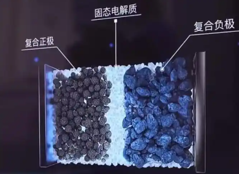
Halide electrolytes offer a complementary property set. They support fast lithium-ion conduction and possess a wide electrochemical stability window with excellent resistance to oxidation at high potentials. Their weakness lies on the anode side, where they are less stable against lithium metal. This complementarity motivates the heterostructured design that I adopted: a sulfide layer facing the anode and a halide layer facing the cathode. The halide layer suppresses side reactions at the cathode side, while the sulfide layer maintains low interfacial resistance at the anode side.
The overall cell reaction that I aim to stabilize can be written in simplified form as:
$$ \mathrm{LiNi_{0.8}Co_{0.1}Mn_{0.1}O_{2}} + x\,\mathrm{Li^{+}} + x\,\mathrm{e^{-}} \rightleftharpoons \mathrm{Li_{1+x}Ni_{0.8}Co_{0.1}Mn_{0.1}O_{2}} $$
In a sulfide-only solid electrolyte cell, the parasitic oxidation reaction at the cathode interface competes with this desired reaction:
$$ \mathrm{Li_6PS_5Cl} \rightarrow \mathrm{Li_6PS_5Cl_{1-2y}S_{2y}} + y\,\mathrm{S} + 2y\,\mathrm{e^{-}} $$
The irreversible sulfur oxidation not only blocks ionic transport but also causes continuous impedance growth. The halide layer alters the local chemical environment so that this reaction is suppressed, as I demonstrate below.
2. Experimental Methods
2.1 Preparation of the Sulfide Solid Electrolyte
I prepared the sulfide solid electrolyte by combining high-energy ball milling with subsequent annealing. The precursor mixture was formulated according to the molar ratio LiCl : Li2S : P2S5 = 6 : 5 : 1. All weighing and handling steps were performed inside an argon-filled glovebox with moisture and oxygen levels maintained below 0.1 ppm.
The raw materials were first hand-ground for 10 min to homogenize the mixture, then transferred into a 100 mL zirconia milling jar. Ball milling was carried out at 500 rpm for 20 h with a ball-to-powder ratio of 20 : 1. The resulting precursor powder was cold-pressed into pellets under 250 MPa, sealed inside high-purity quartz tubes, and annealed at 550 °C for 5 h under argon. After annealing, the pellets were hand-ground in an agate mortar for 10 min to obtain the final Li6PS5Cl (LPSC) sulfide solid electrolyte.
2.2 Preparation of the Halide Solid Electrolyte
I synthesized the halide solid electrolyte through a liquid-phase route. The starting materials were weighed according to the molar ratio LiCl : InCl3·4H2O = 3 : 1 and dissolved in deionized water. The solution was ultrasonicated for 2 h to ensure complete dissolution, then evaporated at 80 °C to obtain the precursor. The dried precursor was sealed into a quartz tube under vacuum, heated to 200 °C, held for 5 h, and finally allowed to cool naturally to room temperature. The product was ground into powder to yield the Li3InCl6 (LIC) halide solid electrolyte.
2.3 Bilayer Composite Electrolyte Membrane and Cell Assembly
All assembly steps were conducted inside an argon-protected glovebox. The composite cathode was prepared by mixing the nickel-rich active material LiNi0.8Co0.1Mn0.1O2 (NCM811), solid electrolyte powder, and conductive carbon (Super-P) in a mass ratio of 70 : 25 : 5. For the control samples, LPSC powder was used in the cathode; for the modified samples, LIC powder was used.
The cell was built in a 10 mm diameter die. A lithium metal foil was placed on the anode side, and 70 mg of LPSC powder was spread over it. Then 10 mg, 30 mg, or 50 mg of LIC powder was layered on top, followed by the composite cathode. The whole stack was pressed at 350 MPa for 5 min to form a dense electrolyte pellet. The assembled solid electrolyte cell was then fixed in a stainless steel outer mold for electrochemical testing.
The sample naming scheme is summarized in Table 1.
| Sample Designation | Electrolyte Configuration | LIC Mass (mg) | Cathode Solid Electrolyte |
|---|---|---|---|
| ASSB-LPSC | Single-layer LPSC | 0 | LPSC |
| ASSB-LIC-A | Bilayer LPSC/LIC | 10 | LIC |
| ASSB-LIC-B | Bilayer LPSC/LIC | 30 | LIC |
| ASSB-LIC-C | Bilayer LPSC/LIC | 50 | LIC |
2.4 Materials Characterization and Electrochemical Testing
I analyzed the crystal structure of the prepared solid electrolytes by X-ray diffraction (XRD) using Cu Kα radiation with a wavelength of λ = 1.540 6 Å. Electrochemical tests were performed on a high-precision battery test system. Galvanostatic rate tests and cycling tests were conducted between 2.8 V and 4.3 V with 1C defined as 200 mAh·g−1. Electrochemical impedance spectroscopy (EIS) and cyclic voltammetry (CV) were carried out on an electrochemical workstation.
3. Results and Discussion
3.1 Crystal Structure of the Solid Electrolytes
The XRD patterns that I collected confirm that the LPSC electrolyte adopts the cubic argyrodite structure. The characteristic diffraction peaks match the expected reference pattern, and no impurity phases such as Li2S are detectable, which indicates that the ball-milling and annealing route produced a highly pure sulfide phase. The LIC electrolyte displays sharp diffraction peaks consistent with a monoclinic structure, reflecting good crystallinity.
The lattice parameters that I extracted from the diffraction data are collected in Table 2.
| Electrolyte | Crystal System | Space Group | Conductivity at 25 °C (S·cm−1) | Anode Compatibility | Cathode Compatibility |
|---|---|---|---|---|---|
| Li6PS5Cl (LPSC) | Cubic (argyrodite) | F-43m | > 10−3 | Excellent | Poor above 3.8 V |
| Li3InCl6 (LIC) | Monoclinic | C2/m | ≈ 10−3 | Moderate | Excellent up to 4.5 V |
The complementarity shown in Table 2 is precisely what motivates the bilayer architecture. I use LPSC where reduction stability matters, and LIC where oxidation stability matters.
3.2 Charge–Discharge Cycling Performance
To evaluate polarization behavior and tolerance to different current densities, I compared the rate performance of all four samples. Under a 0.1C rate between 2.8 V and 4.3 V, the first charge–discharge curves reveal important differences.
The unmodified ASSB-LPSC solid electrolyte cell exhibits a large voltage hysteresis, meaning that the potential difference ΔV between the charge plateau and the discharge plateau is substantial. A long oxidative tail appears during charging, which I attribute to the irreversible oxidation of sulfur at high voltage, producing a high-impedance cathode–electrolyte interphase. In contrast, the three bilayer cells display much smoother curves and lower polarization voltages. Among them, ASSB-LIC-B delivers the highest discharge specific capacity of 213.1 mAh·g−1, and its initial Coulombic efficiency (ICE) rises from 81.2% to 89.8%.
The ICE improvement can be expressed quantitatively as:
$$ \mathrm{ICE} = \frac{Q_{\text{discharge,1}}}{Q_{\text{charge,1}}} \times 100\% $$
$$ \Delta \mathrm{ICE} = 89.8\% – 81.2\% = 8.6\% $$
This improvement demonstrates that the halide layer isolates the nickel-rich cathode from the sulfide electrolyte and suppresses the parasitic side reaction current. The rate and cycling results reinforce this conclusion. The unmodified cell loses capacity rapidly as the rate increases. In contrast, ASSB-LIC-B retains 201.2 mAh·g−1 at 0.2C, 193.5 mAh·g−1 at 0.5C, and 187.6 mAh·g−1 at 1C. Even at a high rate of 2C, it still delivers approximately 163.1 mAh·g−1. This excellent rate response originates from the favorable lithium-ion transport kinetics across the heterointerface.
More importantly, in the subsequent 0.5C cycling segment, the unmodified sample shows an obvious capacity drop when returning to 0.5C, whereas the bilayer solid electrolyte cell samples remain far more stable. For ASSB-LIC-B specifically, the 0.5C capacity retention after 50 cycles reaches 98.4%, with the Coulombic efficiency remaining above 99.8% throughout.
The capacity retention can be calculated as:
$$ R_{50} = \frac{Q_{50}}{Q_{2}} \times 100\% = 98.4\% $$
These results provide strong evidence that the halide solid electrolyte layer maintains good compatibility with the cathode over long cycling, prevents oxidation of the sulfide solid electrolyte, and avoids interfacial contact failure.
The rate performance data are summarized in Table 3.
| Rate | ASSB-LPSC (mAh·g−1) | ASSB-LIC-A (mAh·g−1) | ASSB-LIC-B (mAh·g−1) | ASSB-LIC-C (mAh·g−1) |
|---|---|---|---|---|
| 0.1C | Low, high hysteresis | ≈ 200 | 213.1 | ≈ 198 |
| 0.2C | Rapid decay | ≈ 190 | 201.2 | ≈ 188 |
| 0.5C | Rapid decay | ≈ 182 | 193.5 | ≈ 180 |
| 1C | Rapid decay | ≈ 175 | 187.6 | ≈ 172 |
| 2C | Severe decay | ≈ 150 | 163.1 | ≈ 148 |
| 50-cycle retention at 0.5C | Poor | ≈ 96% | 98.4% | ≈ 95% |
| Coulombic efficiency | Below 99% | > 99.5% | > 99.8% | > 99.5% |
The non-monotonic dependence on LIC mass deserves comment. Increasing the LIC layer from 10 mg to 30 mg improves performance, but increasing it further to 50 mg reduces capacity. I explain this by considering two competing effects. A thicker halide layer provides better cathode protection, but it also adds a serial ionic resistance that scales with thickness according to:
$$ R_{\text{LIC}} = \frac{L}{\sigma_{\text{LIC}} \cdot A} $$
where L is the layer thickness, σ is the ionic conductivity, and A is the cross-sectional area. Thus there exists an optimum thickness that balances protection against added resistance, and 30 mg represents that optimum in my experiments.
3.3 Electrochemical Impedance Analysis
I performed alternating-current impedance measurements on the assembled solid electrolyte cell samples and analyzed the spectra quantitatively. The Nyquist plot consists of a high-frequency semicircle representing bulk and grain-boundary resistance, a mid-frequency semicircle characterizing the charge-transfer resistance Rct at the electrode/electrolyte interface, and a low-frequency inclined line representing the Warburg impedance ZW.
The equivalent circuit that I used for fitting is:
$$ Z(\omega) = R_{\Omega} + \frac{R_{\text{ct}}}{1 + (j\omega R_{\text{ct}} C_{\text{dl}})^{n}} + \sigma_{W}(1-j)\omega^{-1/2} $$
Fitting with this equivalent circuit shows that the ohmic resistances of the samples differ only slightly, which indicates that the two electrolytes possess essentially the same ionic conductivity. The mid-frequency interfacial resistance, however, differs dramatically. The unmodified NCM811/LPSC solid electrolyte cell exhibits an impedance value as high as 325 Ω, indicating a large carrier transport barrier at the NCM811/LPSC interface caused by side reactions after the first charge–discharge cycle. After incorporating LIC, the impedance of all modified cells decreases markedly. ASSB-LIC-B shows the lowest value at 86 Ω.
The impedance reduction ratio can be quantified as:
$$ \eta_{Z} = \frac{325 – 86}{325} \times 100\% = 73.5\% $$
The reason for this large reduction is that LIC not only has high ionic conductivity but also possesses better energy-level matching with the nickel-rich cathode. This matching effectively mitigates the space-charge layer effect and increases the lithium-ion migration rate within the electrode.
The fitted impedance parameters are compiled in Table 4.
| Sample | RΩ (Ω) | Rct (Ω) | ZW Coefficient | Interpretation |
|---|---|---|---|---|
| ASSB-LPSC | ≈ 25 | 325 | High | Severe sulfide oxidation, thick CEI |
| ASSB-LIC-A | ≈ 26 | ≈ 110 | Moderate | Partial protection, thin halide layer |
| ASSB-LIC-B | ≈ 25 | 86 | Low | Optimal protection and transport balance |
| ASSB-LIC-C | ≈ 27 | ≈ 130 | Moderate | Excess serial resistance from thick layer |
3.4 Cyclic Voltammetry
I verified the electrochemical window and redox reversibility of the solid electrolyte cell samples by cyclic voltammetry. For the unmodified ASSB-LPSC, the first CV scan shows an anomalously large oxidation peak current when the potential reaches 3.0 V, along with broadening of the peak shape, and an obvious irreversible oxidation peak near 3.8 V. This feature corresponds to the oxidative decomposition of sulfur in LPSC. In the reverse reduction scan, the corresponding reduction peak current is very small, indicating that the oxidation products cannot return to their initial state, which inevitably causes loss of active material.
After LIC modification, the ASSB-LIC-B solid electrolyte cell displays well-defined sharp peaks, with the oxidation peak near 4.3 V. Even when the scan voltage reaches 4.5 V, the modified sample shows no spurious additional peaks, and the current density in the non-reactive region remains very low. This confirms that LIC has excellent high-voltage tolerance above 4.5 V and functions as a shield that protects the sulfide solid electrolyte from oxidative damage at high potential, ensuring stable operation under high-voltage conditions.
The anodic stability criterion that I apply can be stated as:
$$ \left. \frac{\partial i}{\partial E} \right|_{E > E_{\text{ox}}} \approx 0 \quad \text{for the protected cell} $$
where i is the current density and E is the electrode potential. The near-zero slope beyond the main oxidation peak indicates that no additional parasitic reactions are activated, which is the signature of an electrochemically robust interface.
3.5 Mechanistic Interpretation of Interfacial Stabilization
The combined evidence from cycling, impedance, and voltammetry supports a coherent mechanistic picture. In a single-layer sulfide solid electrolyte cell, the cathode surface potential drives sulfur oxidation, generating a growing interphase whose ionic resistance increases with cycle number. The cell therefore shows high initial polarization, low ICE, and rapid capacity fade. In the bilayer architecture, the halide interlayer acts as a chemically inert buffer. Because the halide has a wider anodic stability window, the sulfide never directly contacts the high-potential cathode surface. The cathode-side reactions are thus restricted to the desired lithium extraction and insertion processes.
The interfacial charge-transfer resistance at the cathode can be described as a series combination:
$$ R_{\text{interface}} = R_{\text{cathode/LIC}} + R_{\text{LIC}} + R_{\text{LIC/LPSC}} $$
In the unmodified case, the corresponding expression contains a rapidly growing decomposition term:
$$ R_{\text{interface, LPSC}} = R_{\text{cathode/LPSC}} + R_{\text{CEI}}(t) $$
where RCEI(t) increases monotonically with time because the interphase thickens. The bilayer design eliminates this growing term, which explains why the impedance of ASSB-LIC-B remains low and stable.
The lithium-ion flux across the bilayer can be approximated by a series diffusion model:
$$ J_{\text{Li}^+} = \frac{\Delta \mu_{\text{Li}}}{F \left( \dfrac{L_{\text{LIC}}}{\sigma_{\text{LIC}}} + \dfrac{L_{\text{LPSC}}}{\sigma_{\text{LPSC}}} \right)} $$
where ΔμLi is the chemical potential difference driving transport, F is the Faraday constant, and L and σ denote thickness and conductivity of each layer. Because the two conductivities are comparable, the addition of the halide layer increases the total resistance only modestly, while the benefit of suppressing the growing interphase resistance far outweighs this penalty.
4. Comparative Performance Summary
To place the results in perspective, Table 5 compares the key performance metrics of the baseline and optimized solid electrolyte cell configurations.
| Metric | ASSB-LPSC (Baseline) | ASSB-LIC-B (Optimized) | Relative Change |
|---|---|---|---|
| Initial discharge capacity at 0.1C | ≈ 175 mAh·g−1 | 213.1 mAh·g−1 | +21.8% |
| Initial Coulombic efficiency | 81.2% | 89.8% | +8.6 percentage points |
| Capacity at 2C | Severe decay | 163.1 mAh·g−1 | Substantial improvement |
| 50-cycle retention at 0.5C | Poor | 98.4% | Major improvement |
| Coulombic efficiency during cycling | Below 99% | > 99.8% | Improved stability |
| Interfacial charge-transfer resistance | 325 Ω | 86 Ω | −73.5% |
| Anodic stability limit | ≈ 3.8 V | > 4.5 V | Extended window |
The data in Table 5 make clear that the halide interlayer delivers simultaneous improvements in capacity, efficiency, rate capability, cycling stability, and interfacial resistance. These gains are not independent; they all trace back to the suppression of the parasitic oxidation reaction at the cathode interface.
5. Practical Implications for Cell Design
Several practical lessons emerge from this work. First, the halide layer thickness must be optimized rather than maximized. My results show that 30 mg of LIC provides the best balance, whereas 50 mg introduces excess serial resistance. The optimum condition can be expressed as the minimum of the total resistance function:
$$ R_{\text{total}}(L) = R_{0} + \frac{L}{\sigma A} + R_{\text{CEI}}(L) $$
where RCEI(L) decreases with increasing L because a thicker layer provides better protection. Setting the derivative with respect to L to zero yields the optimal thickness:
$$ \frac{\partial R_{\text{total}}}{\partial L} = \frac{1}{\sigma A} + \frac{\partial R_{\text{CEI}}}{\partial L} = 0 $$
Second, the bilayer solid electrolyte cell design is compatible with standard cold-pressing fabrication, since both layers are pressed together in a single step at 350 MPa. This simplifies scale-up relative to approaches that require separate sintering or infiltration steps. Third, the use of a nickel-rich NCM811 cathode in combination with a lithium metal anode places the cell at the high-energy-density frontier, and the halide interlayer is what makes this combination viable in a sulfide-based system.
6. Conclusions
I successfully prepared high-purity Li6PS5Cl and Li3InCl6 solid electrolytes by ball milling and liquid-phase synthesis, respectively, and I constructed a heterostructured bilayer electrolyte that forms intimate contact while maintaining chemical independence between the two layers. The introduction of the halide solid electrolyte buffer layer significantly improves the charge–discharge performance of the solid electrolyte cell, and it effectively reduces polarization and charge-transfer resistance between the electrodes.
The optimized ASSB-LIC-B cell achieves a high rate capability, delivering more than 163.1 mAh·g−1 at 2C, and excellent long-term cycling stability, retaining 98.4% of its capacity after 50 cycles. These figures are markedly superior to those of the unmodified sulfide-only solid electrolyte cell. The addition of Li3InCl6 widens the electrochemical window of the cell system, prevents decomposition of the sulfide solid electrolyte under high voltage, and enables better matching with high-voltage cathode materials while preserving interfacial stability.
The broader significance of this work lies in demonstrating that interface engineering through directed heterostructure formation is a practical and effective route toward high-performance all-solid-state batteries. By allowing each electrolyte layer to operate in the potential regime where it is thermodynamically stable, the bilayer solid electrolyte cell circumvents the fundamental incompatibility that has long hindered sulfide-based systems. I believe this strategy can be extended to other electrolyte chemistries and cathode materials, opening new pathways for the development of high-specific-energy all-solid-state batteries.