
As I examine the rapid evolution of global energy systems and the intensifying pursuit of decarbonization, I find that the electric vehicle battery pack has become the pivotal component determining the safety, reliability, and user acceptance of modern electric mobility. The electric vehicle battery pack is not merely an energy storage device; it is a complex electrochemical system in which electrical, thermal, mechanical, and chemical processes are tightly coupled across multiple scales. My aim in this review is to provide a systematic and critical synthesis of the theories and methods that underpin safety management and control of the electric vehicle battery pack, following a logical thread of failure mechanisms, feature extraction, state estimation, and fault prognosis. Throughout this work, I emphasize that accurate state estimation and early fault prognosis of the electric vehicle battery pack are the two most critical technical challenges for ensuring safe and efficient operation.
The scale of the challenge is immense. Global lithium-ion battery shipments reached unprecedented levels in recent years, and the total installed capacity continues to grow exponentially. As the electric vehicle battery pack becomes ubiquitous, thermal runaway events and safety incidents have attracted intense societal attention. I contend that a holistic understanding of the electric vehicle battery pack requires moving beyond single-factor analysis toward multi-physics coupling frameworks that can capture the intricate interactions between thermal, electrical, mechanical, and gas evolution processes.
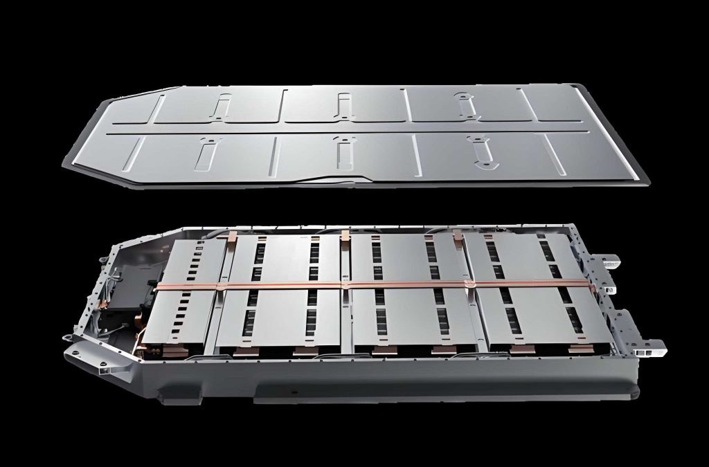
In this review, I define battery safety specifically as safety issues caused by fire, excluding high-voltage safety, insulation failure, and leakage protection. I distinguish between “fault,” which refers to functional deviation or performance abnormality, and “safety,” which relates to fire and thermal runaway. A fault may evolve into a safety problem, but not all faults lead to safety incidents. Conversely, safety problems may arise from external mechanical abuse without any prior internal fault. This distinction is crucial for developing effective safety management strategies for the electric vehicle battery pack.
1. Failure Mechanisms under Multi-Factor Coupling
In real-world operation, the electric vehicle battery pack experiences coupled electrical, thermal, and mechanical stresses. The failure process involves multi-level responses across materials, structures, and interfaces, exhibiting complex cross-scale and dynamic evolution mechanisms. I systematically analyze three typical coupling modes: thermal-electrical coupling, mechanical-electrical-thermal coupling, and thermal-gas coupling. I also introduce knowledge graph-based methods for structured semantic representation and dynamic reasoning of complex failure processes.
1.1 Thermal-Electrical Coupling
Thermal-electrical coupling failure is one of the most common failure modes in the electric vehicle battery pack. During charging and discharging, heat accumulates due to internal resistance losses and side reactions. If heat dissipation is insufficient, temperature rises, which in turn accelerates electrochemical reactions, increases internal resistance, and degrades materials, forming a positive feedback loop. I express the general heat balance for a battery cell as:
$$m C_p \frac{dT}{dt} = Q_{ohm} + Q_{react} + Q_{exo} – Q_{diss}$$
where \(m\) is mass, \(C_p\) is specific heat capacity, \(T\) is temperature, \(t\) is time, \(Q_{ohm}\) is ohmic heat, \(Q_{react}\) is reaction heat, \(Q_{exo}\) is exothermic side reaction heat, and \(Q_{diss}\) is heat dissipation. Under high temperature and high state of charge (SOC), side reactions accelerate, leading to loss of lithium inventory (LLI) and loss of active material (LAM). I summarize the key findings in Table 1.
| Condition | Key observation | Failure mode | Reference approach |
|---|---|---|---|
| High temperature storage | Accelerated side reactions, LLI and LAM | Capacity fade | Storage simulation tests |
| Overcharge and overdischarge | Impedance evolution, structural degradation | Internal short circuit | Electrochemical impedance spectroscopy |
| Low temperature high-rate charging | Lithium plating and dendrite growth | Capacity loss, resistance increase | Half-cell modeling |
| High temperature overdischarge | Material decomposition and agglomeration | Accelerated aging | 18650 cell testing |
For the electric vehicle battery pack, thermal-electrical coupling can trigger a “short circuit–heat generation” runaway path. When internal short circuits occur due to dendrite penetration or local overcharge, current density concentrates abnormally, rapidly inducing heat generation and superimposed side reactions. I note that the SOC threshold for thermal runaway is significantly advanced under overcharge and overheating coupling, especially in extreme high-temperature environments.
1.2 Mechanical-Electrical-Thermal Coupling
Mechanical-electrical-thermal coupling integrates mechanical stress, electrochemical processes, and thermal behavior. This is one of the most complex coupling failure mechanisms in the electric vehicle battery pack. When the battery undergoes collision, compression, or drop loading, electrode structures deform, cracks form, and contact interfaces degrade, disrupting current paths and increasing interfacial impedance.
I express the coupling relationship through a multi-physics model:
$$\nabla \cdot \sigma + f = 0$$
$$j = \sigma_e \nabla \phi$$
$$\rho C_p \frac{\partial T}{\partial t} = \nabla \cdot (k \nabla T) + Q_{elec} + Q_{mech}$$
where \(\sigma\) is stress tensor, \(f\) is body force, \(j\) is current density, \(\sigma_e\) is electrical conductivity, \(\phi\) is potential, \(\rho\) is density, \(k\) is thermal conductivity, \(Q_{elec}\) is electrical heat, and \(Q_{mech}\) is mechanical heat. Mechanical deformation can lead to separator puncture, electrode short-circuiting, and localized high current density regions, forming a mechanical-electrical-thermal runaway channel. I summarize key observations in Table 2.
| Loading condition | Mechanical response | Electrical response | Thermal response |
|---|---|---|---|
| Dynamic impact | Micro-cracks, active material delamination | Impedance increase, capacity fade | Localized heating |
| Compression at different SOC | Electrode expansion, stiffness change | Current path disruption | Short-circuit heat |
| High loading rate with aging | Structural instability | Voltage decay | Electrolyte decomposition, thermal runaway |
1.3 Thermal-Gas Coupling
Thermal-gas coupling manifests as temperature rise-induced gas phase reactions, internal pressure increase, and structural integrity damage. Under thermal abuse, overcharge, or external short circuit, electrolyte and electrode materials undergo vigorous side reactions, releasing large amounts of heat and active gases such as H₂, CO, and CO₂. Internal pressure rises, potentially causing shell expansion, deformation, or rupture. I summarize the coupling in Table 3.
| Aspect | Description | Consequence |
|---|---|---|
| Gas generation | Electrolyte decomposition, SEI breakdown | H₂, CO, CO₂, HF release |
| Pressure rise | Gas accumulation in sealed cell | Shell expansion or rupture |
| Venting | Flammable gas ejection | Combustion or explosion risk |
I emphasize that thermal-gas coupling does not directly cause thermal runaway but serves as a critical intermediate link. Understanding gas generation, accumulation, pressure rise, and venting dynamics is essential for early warning and active safety control of the electric vehicle battery pack.
1.4 Knowledge Graph for Battery Failure
Traditional failure analysis methods suffer from low diagnostic efficiency, high cost, and limited generalization. Knowledge graphs offer a structured semantic network for unifying heterogeneous data and modeling relationships among failure modes, causes, environmental stresses, and material degradation mechanisms. I propose that constructing a battery failure knowledge graph is a promising direction for the electric vehicle battery pack.
Formally, a knowledge graph can be represented as:
$$G = (E, R, T)$$
where \(E\) is the set of entities (failure modes, causes, features), \(R\) is the set of relations, and \(T\) is the set of triples \((h, r, t)\) with \(h, t \in E\) and \(r \in R\). Graph neural networks can then be applied for dynamic reasoning:
$$h_v^{(l+1)} = \sigma\left( \sum_{u \in \mathcal{N}(v)} \frac{1}{c_{vu}} W^{(l)} h_u^{(l)} \right)$$
where \(h_v^{(l)}\) is the node representation, \(\mathcal{N}(v)\) is the neighborhood, \(c_{vu}\) is a normalization constant, \(W^{(l)}\) is a learnable weight matrix, and \(\sigma\) is a nonlinear activation function. This enables the electric vehicle battery pack to achieve early fault warning and intelligent diagnosis.
2. Multi-Dimensional Information Detection and Feature Extraction
To accurately estimate the state of the electric vehicle battery pack, I must first establish a real-time monitoring system that acquires high-confidence data. Voltage, current, and temperature are the primary external measurements. However, voltage data alone are susceptible to SOC fluctuations and temperature variations. Current sensors are often limited to total pack current due to cost and installation complexity. I summarize the detection methods in Table 4.
| Method | Measured parameters | Advantages | Limitations |
|---|---|---|---|
| External voltage sensing | Cell and module voltages | Simple, stable, low cost | Influenced by SOC and temperature |
| Current sensing | Total pack current | Direct, reliable | Branch current imbalance not captured |
| Temperature sensing | Surface and ambient temperature | Thermal monitoring | Internal temperature not directly measured |
| Implanted sensors | Internal strain, pressure, gas | Direct internal measurement | Cost, sealing, compatibility issues |
| Indirect mapping | Internal states from external parameters | Non-invasive | Model dependence, validation challenges |
Implanted sensors, such as fiber Bragg gratings and Fabry-Perot interferometers, can directly capture internal electrochemical, thermal, and mechanical parameters. However, challenges remain in electromagnetic shielding, power supply stability, and long-term reliability under high-temperature conditions. I argue that a hybrid approach combining external and internal sensing is essential for comprehensive monitoring of the electric vehicle battery pack.
2.1 Feature Extraction Methods
Data analysis methods extract features from voltage, temperature, incremental capacity curves, and energy signals. I express the incremental capacity as:
$$\frac{dQ}{dV} = f(V)$$
where \(Q\) is capacity and \(V\) is voltage. Features such as peak voltage, local extrema, and half-peak width can be extracted. Principal component analysis (PCA) is often used for feature fusion:
$$Y = W^T X$$
where \(X\) is the original feature matrix, \(W\) is the projection matrix, and \(Y\) is the reduced feature set. Multi-source information fusion integrates battery data with environmental data such as temperature, humidity, and road conditions. I summarize fusion methods in Table 5.
| Method | Input data | Output features | Application |
|---|---|---|---|
| Incremental capacity analysis | Voltage-capacity curves | Peak voltage, peak height | SOH estimation |
| Gray relational analysis | Voltage, temperature, energy | Correlation features | Failure analysis |
| Particle swarm optimization | Differential capacity curves | Optimal feature subset | Fault diagnosis |
| Canonical correlation analysis | Multi-source features | Fused representation | State estimation |
| Principal component analysis | Cycle life, resistance, relaxation time | Reduced features | SOH estimation |
3. State Estimation Methods
State estimation of the electric vehicle battery pack includes SOC, state of energy (SOE), state of health (SOH), and state of power (SOP). I classify methods into experimental, model-based, data-driven, and big data plus large model approaches. I define SOC as:
$$SOC(t) = SOC(t_0) – \frac{1}{Q_{nom}} \int_{t_0}^{t} I(\tau) d\tau$$
where \(Q_{nom}\) is nominal capacity and \(I\) is current. SOH is defined as:
$$SOH = \frac{Q_{current}}{Q_{nominal}} \times 100\%$$
I summarize the methods in Table 6.
| Method | Advantages | Disadvantages | Application scenarios |
|---|---|---|---|
| Experimental methods | High accuracy, clear physical meaning | High cost, long test period | Laboratory calibration |
| Model-based methods | Interpretability | Complex modeling, large computation | On-board BMS |
| Data-driven methods | High accuracy, fast computation | Data dependence, black-box | Complex operating conditions |
| Big data and large models | Strong generalization, multi-modal fusion | High computational cost | Multi-scenario, multi-material systems |
3.1 Experimental Methods
Experimental methods include direct measurement and indirect characterization. Direct methods measure capacity, voltage, and internal resistance. Indirect methods explore mapping relationships between voltage, current, temperature, and battery states. For example, incremental capacity curves can be used to extract health factors:
$$HF = g\left(\frac{dQ}{dV}, V\right)$$
where \(HF\) is the health factor. These methods offer high accuracy but depend on precision instruments and long test cycles.
3.2 Model-Based Methods
Model-based methods construct physical or mathematical models. Equivalent circuit models (ECMs) are widely used. A second-order RC model is expressed as:
$$\begin{cases}
V_{t} = V_{oc} – I R_0 – V_1 – V_2 \\
\frac{dV_1}{dt} = -\frac{V_1}{R_1 C_1} + \frac{I}{C_1} \\
\frac{dV_2}{dt} = -\frac{V_2}{R_2 C_2} + \frac{I}{C_2}
\end{cases}$$
where \(V_t\) is terminal voltage, \(V_{oc}\) is open-circuit voltage, \(R_0\) is ohmic resistance, \(R_1, C_1, R_2, C_2\) are polarization parameters. The extended Kalman filter (EKF) is commonly used for state estimation:
$$\hat{x}_{k|k-1} = A \hat{x}_{k-1|k-1} + B u_{k-1}$$
$$P_{k|k-1} = A P_{k-1|k-1} A^T + Q$$
$$K_k = P_{k|k-1} H^T (H P_{k|k-1} H^T + R)^{-1}$$
$$\hat{x}_{k|k} = \hat{x}_{k|k-1} + K_k (z_k – H \hat{x}_{k|k-1})$$
where \(\hat{x}\) is the state estimate, \(P\) is covariance, \(K_k\) is Kalman gain, \(Q\) and \(R\) are noise covariances, and \(z_k\) is measurement. Electrochemical models such as the pseudo-two-dimensional (P2D) model provide higher fidelity:
$$\frac{\partial c_s}{\partial t} = \frac{D_s}{r^2} \frac{\partial}{\partial r} \left( r^2 \frac{\partial c_s}{\partial r} \right)$$
where \(c_s\) is solid-phase lithium concentration and \(D_s\) is diffusion coefficient. The Butler-Volmer equation describes reaction kinetics:
$$j = j_0 \left[ \exp\left(\frac{\alpha_a F \eta}{RT}\right) – \exp\left(-\frac{\alpha_c F \eta}{RT}\right) \right]$$
where \(j\) is current density, \(j_0\) is exchange current density, \(\alpha_a\) and \(\alpha_c\) are transfer coefficients, \(F\) is Faraday constant, \(\eta\) is overpotential, \(R\) is gas constant, and \(T\) is temperature.
3.3 Data-Driven Methods
Data-driven methods leverage machine learning and deep learning. Recurrent neural networks (RNNs), long short-term memory (LSTM) networks, and convolutional neural networks (CNNs) are widely used. The LSTM cell is governed by:
$$f_t = \sigma(W_f [h_{t-1}, x_t] + b_f)$$
$$i_t = \sigma(W_i [h_{t-1}, x_t] + b_i)$$
$$\tilde{C}_t = \tanh(W_C [h_{t-1}, x_t] + b_C)$$
$$C_t = f_t \odot C_{t-1} + i_t \odot \tilde{C}_t$$
$$o_t = \sigma(W_o [h_{t-1}, x_t] + b_o)$$
$$h_t = o_t \odot \tanh(C_t)$$
The Transformer architecture uses self-attention:
$$Attention(Q, K, V) = softmax\left(\frac{QK^T}{\sqrt{d_k}}\right) V$$
where \(Q\), \(K\), and \(V\) are query, key, and value matrices, and \(d_k\) is the dimension of the key vectors. These methods achieve high accuracy but require large amounts of high-quality data.
3.4 Big Data and Large Model Methods
Big data and large model methods integrate pre-trained language models (PLMs) and large language models (LLMs) for state estimation. The fine-tuning process can be expressed as:
$$\mathcal{L}(\theta) = -\sum_{i=1}^{N} \log P(y_i | x_i; \theta)$$
where \(\theta\) represents model parameters, \(x_i\) is input, and \(y_i\) is target. These methods improve generalization across different battery chemistries and operating conditions. I summarize the evolution from traditional methods to large model methods in Table 7.
| Generation | Core technique | Data requirement | Generalization |
|---|---|---|---|
| First | Ampere-hour integration, OCV | Low | Poor |
| Second | Equivalent circuit models, Kalman filters | Medium | Moderate |
| Third | Machine learning, deep learning | High | Good |
| Fourth | Big data, large models, transfer learning | Very high | Excellent |
4. Fault Prognosis Methods
Fault prognosis of the electric vehicle battery pack aims to detect early abnormalities, identify fault types, and predict safety risks. I classify methods into model-based, knowledge-based, data-driven, and big data plus large model approaches. I summarize them in Table 8.
| Method | Advantages | Disadvantages | Application |
|---|---|---|---|
| Model-based | Physical interpretability | Modeling difficulty, poor robustness | Laboratory validation |
| Knowledge-based | Expert rules, interpretable | Knowledge acquisition bottleneck | Known fault patterns |
| Data-driven | No physical model needed, adaptive | Data dependence, black-box | Historical data analysis |
| Big data and large models | Cross-scenario generalization | High computational cost | Cloud-edge collaboration |
4.1 Model-Based Methods
Model-based methods use equivalent circuit models, electrochemical models, observers, and parameter identification. For instance, a sliding mode observer can be designed as:
$$\dot{\hat{x}} = A\hat{x} + Bu + L(y – \hat{y}) + \rho \, \text{sign}(y – \hat{y})$$
where \(L\) is observer gain and \(\rho\) is switching gain. Internal short circuit resistance can be estimated using recursive least squares:
$$\hat{\theta}_k = \hat{\theta}_{k-1} + K_k (y_k – \phi_k^T \hat{\theta}_{k-1})$$
$$K_k = \frac{P_{k-1} \phi_k}{\lambda + \phi_k^T P_{k-1} \phi_k}$$
$$P_k = \frac{1}{\lambda} (I – K_k \phi_k^T) P_{k-1}$$
where \(\theta\) is parameter vector, \(\phi\) is regressor, and \(\lambda\) is forgetting factor.
4.2 Knowledge-Based Methods
Knowledge-based methods use expert systems, fault trees, fuzzy logic, and case-based reasoning. Fuzzy logic membership functions can be expressed as:
$$\mu_A(x) = \exp\left(-\frac{(x – c)^2}{2\sigma^2}\right)$$
where \(c\) and \(\sigma\) are the center and width of the fuzzy set. These methods are interpretable but struggle with novel faults.
4.3 Data-Driven Methods
Data-driven methods extract anomalies from operational data. Support vector machines (SVMs) use the kernel trick:
$$f(x) = \text{sign}\left(\sum_{i=1}^{N} \alpha_i y_i K(x_i, x) + b\right)$$
where \(\alpha_i\) are Lagrange multipliers, \(y_i\) are labels, and \(K\) is the kernel function. Random convolution kernel transformations and Gaussian process classifiers have also been applied for multi-fault diagnosis.
4.4 Big Data and Large Model Methods
Large models enable long-sequence modeling and multi-modal fusion. A spatio-temporal transformer for fault diagnosis can be represented as:
$$Z = \text{Transformer}(X_{1:T})$$
$$\hat{y} = \text{Softmax}(W Z + b)$$
where \(X_{1:T}\) is the input sequence and \(\hat{y}\) is the fault probability. These methods achieve superior performance in cross-scenario applications but require significant computational resources.
5. Future Directions and Conclusions
Based on my review, I identify three key challenges for safety management of the electric vehicle battery pack: unclear cross-scale correlations of failure mechanisms, insufficient coupling analysis of internal and external parameters, and limited generalization capability of existing models under complex operating conditions. To address these, I propose the following future research directions.
First, construction of multi-factor coupled failure knowledge graphs. I recommend building structured, extensible knowledge graphs that integrate failure modes, triggering factors, environmental stresses, and material degradation mechanisms. This will provide knowledge support for data-driven intelligent diagnosis and reasoning.
Second, multi-dimensional characterization and fusion sensing of internal and external state parameters. I advocate for developing multi-source heterogeneous sensing and high-precision perception technologies to achieve multi-dimensional feature extraction and fusion modeling. This will improve the accuracy and robustness of state estimation and fault prognosis for the electric vehicle battery pack.
Third, big data and large model-based state estimation and fault prognosis. I believe that combining high-dimensional operational data, multi-scale simulation data, and real-world fault cases will enable the construction of large model frameworks with cross-condition generalization and multi-task collaboration capabilities. By integrating deep learning, graph neural networks, and transfer learning, these frameworks can achieve high-precision state estimation and early fault warning in multiple scenarios.
In conclusion, the electric vehicle battery pack is a complex system whose safety management requires a holistic, multi-disciplinary approach. I am confident that the integration of advanced sensing, multi-physics modeling, knowledge graphs, and large-scale artificial intelligence will revolutionize the way we monitor, estimate, and prognose the health of the electric vehicle battery pack. The transition from reactive maintenance to proactive safety management will be enabled by these technologies, ultimately ensuring the safe, reliable, and efficient operation of electric vehicles worldwide.
To further illustrate the integration of these methods, I present a summary of the proposed framework in Table 9.
| Layer | Function | Key technologies | Output |
|---|---|---|---|
| Data acquisition | Multi-dimensional sensing | Voltage, current, temperature, strain, gas sensors | Raw data streams |
| Feature extraction | Signal processing and fusion | ICA, PCA, CCA, wavelet transform | Health features |
| State estimation | SOC, SOH, SOP, SOE estimation | EKF, LSTM, Transformer, PLM | State trajectories |
| Fault prognosis | Early fault detection and prediction | Knowledge graph, GNN, LLM | Fault warnings |
| Decision and control | Active safety management | Cloud-edge collaboration, reinforcement learning | Control actions |
I conclude that the future of electric vehicle battery pack safety lies in the seamless integration of physical mechanisms, data-driven intelligence, and knowledge-based reasoning. The electric vehicle battery pack will evolve from a passive energy storage unit into an intelligent, self-aware system capable of predicting and preventing failures before they occur. This vision requires sustained research efforts across materials science, electrochemistry, control theory, and artificial intelligence. I am optimistic that the coming decade will witness transformative advances in this field, making the electric vehicle battery pack safer, more reliable, and more sustainable than ever before.
Finally, I express my hope that this review serves as a useful reference for researchers and engineers working on the safety management and control of the electric vehicle battery pack. The challenges are significant, but so are the opportunities. By combining rigorous science with innovative engineering, we can unlock the full potential of the electric vehicle battery pack and accelerate the transition to a clean energy future.