
In this work, I propose an active disturbance rejection control method for the bearing rotor speed of a PMSM electric motor. The PMSM electric motor is widely used in electric vehicles, aerospace systems, high-speed rail traction, industrial automation, and precision servo applications because of its high efficiency, high power density, and excellent dynamic performance. However, the bearing rotor speed of a PMSM electric motor is sensitive to load disturbances, parameter variations, nonlinear magnetic behavior, temperature effects, and unmodeled dynamics. These uncertainties can reduce control accuracy, increase speed fluctuation, and even threaten the stability of the PMSM electric motor drive system. Therefore, I construct a complete mathematical model of the PMSM electric motor as the controlled plant, and I design a controller composed of a tracking differentiator, an extended state observer, and a nonlinear state error feedback law. The resulting active disturbance rejection control method estimates and compensates the total disturbance in real time, so that the bearing rotor speed of the PMSM electric motor can track the desired reference with fast dynamic response and strong anti-interference capability.
The main contribution of my work is not merely the combination of existing modules, but a systematic design procedure for the bearing rotor speed loop of a PMSM electric motor. I first establish the d-q axis voltage equations, the electromagnetic torque equation, and the mechanical motion equation of the PMSM electric motor. I then reformulate the speed dynamics as an integral-chain uncertain system. On this basis, I use a tracking differentiator to arrange the transient profile of the desired speed and to extract its differential signal. I use an extended state observer to estimate the bearing rotor speed, its derivative, and the lumped disturbance. I use a nonlinear state error feedback law to generate the preliminary control signal, and I compensate the estimated disturbance to obtain the final q-axis current reference. The experimental results show that the proposed method improves both the dynamic response performance and the disturbance rejection ability of the PMSM electric motor bearing rotor speed control.
1. Introduction
The PMSM electric motor is a nonlinear, multivariable, and strongly coupled system. In practical operation, the bearing rotor speed of a PMSM electric motor is affected by many uncertain factors. Load torque changes, stator resistance variation, permanent magnet flux linkage deviation, inductance variation, friction, and unmodeled dynamics all act on the speed loop. Traditional proportional-integral-derivative control is simple and easy to implement, but it does not explicitly estimate or compensate the total disturbance. As a result, when the PMSM electric motor operates under complex conditions, the conventional proportional-integral-derivative controller may exhibit slow response, large overshoot, or sustained oscillation.
To overcome these limitations, advanced control strategies have been investigated for the PMSM electric motor. Sliding mode control can provide strong robustness, but its performance depends heavily on sliding surface parameters and time-varying gains. Fuzzy coupling control can achieve good synchronization performance, but its behavior is sensitive to parameter drift and rule-base design. In contrast, active disturbance rejection control treats all internal uncertainties and external disturbances as a total disturbance and estimates it using an extended state observer. This makes active disturbance rejection control suitable for the bearing rotor speed control of a PMSM electric motor, because the method does not require an exact model and can actively reject disturbances.
In my design, I focus on the bearing rotor speed of the PMSM electric motor, not only on the electromagnetic torque or current loop. The speed loop is the outer loop of the PMSM electric motor drive, and its performance directly determines the mechanical response. I therefore model the PMSM electric motor in the d-q coordinate frame, derive the speed dynamics, and design the active disturbance rejection controller around the speed state. The proposed method is validated in a MATLAB/Simulink environment using a high-speed PMSM electric motor model. The experimental results demonstrate that the proposed method achieves faster speed tracking and smaller speed fluctuation than two comparison methods.
2. Mathematical Model of the PMSM Electric Motor
To design an effective active disturbance rejection controller for the bearing rotor speed of the PMSM electric motor, I must first construct a mathematical model that captures the dominant electromagnetic and mechanical dynamics. I make several assumptions to simplify the analysis while preserving the essential behavior of the PMSM electric motor. These assumptions are listed in Table 1.
| Assumption | Description |
|---|---|
| Linear magnetic circuit | The magnetic path of the PMSM electric motor is assumed to be linear, so saturation is neglected in the nominal model. |
| No eddy current and hysteresis loss | Iron losses inside the PMSM electric motor are ignored for the purpose of speed controller design. |
| Uniform air gap | The air gap between the stator and rotor of the PMSM electric motor is assumed to be uniform. |
| Constant permanent magnet field | The magnetic field produced by the permanent magnet of the PMSM electric motor is treated as constant. |
| Symmetrical three-phase windings | The stator windings of the PMSM electric motor are assumed to be symmetrical and sinusoidally distributed. |
Under these assumptions, I express the voltage equations of the PMSM electric motor in the two-phase synchronous rotating d-q coordinate frame. The d-axis and q-axis voltage equations are written as follows:
$$
\begin{cases}
u_d = R_s i_d + L_d \dfrac{di_d}{dt} – \omega_e L_q i_q, \\[8pt]
u_q = R_s i_q + L_q \dfrac{di_q}{dt} + \omega_e \left( L_d i_d + \psi_f \right).
\end{cases}
$$
Here, \(u_d\) and \(u_q\) are the d-axis and q-axis voltages of the PMSM electric motor, \(i_d\) and \(i_q\) are the d-axis and q-axis currents, \(L_d\) and \(L_q\) are the d-axis and q-axis inductances, \(R_s\) is the stator resistance, \(\omega_e\) is the electrical angular speed, and \(\psi_f\) is the permanent magnet flux linkage. For a surface-mounted PMSM electric motor, \(L_d\) and \(L_q\) are often close to each other, but I retain the general form to cover interior permanent magnet PMSM electric motor configurations.
The electromagnetic torque of the PMSM electric motor is expressed as:
$$
T_e = \frac{3}{2} p \left[ \psi_f i_q + \left( L_d – L_q \right) i_d i_q \right],
$$
where \(T_e\) is the electromagnetic torque and \(p\) is the number of pole pairs. The mechanical motion equation of the PMSM electric motor is:
$$
J \frac{d\omega_m}{dt} = T_e – T_L – B \omega_m,
$$
where \(J\) is the moment of inertia, \(\omega_m\) is the mechanical angular speed of the bearing rotor, \(T_L\) is the load torque, and \(B\) is the viscous friction coefficient. The relationship between the electrical angular speed and the mechanical angular speed of the PMSM electric motor is:
$$
\omega_e = p \omega_m.
$$
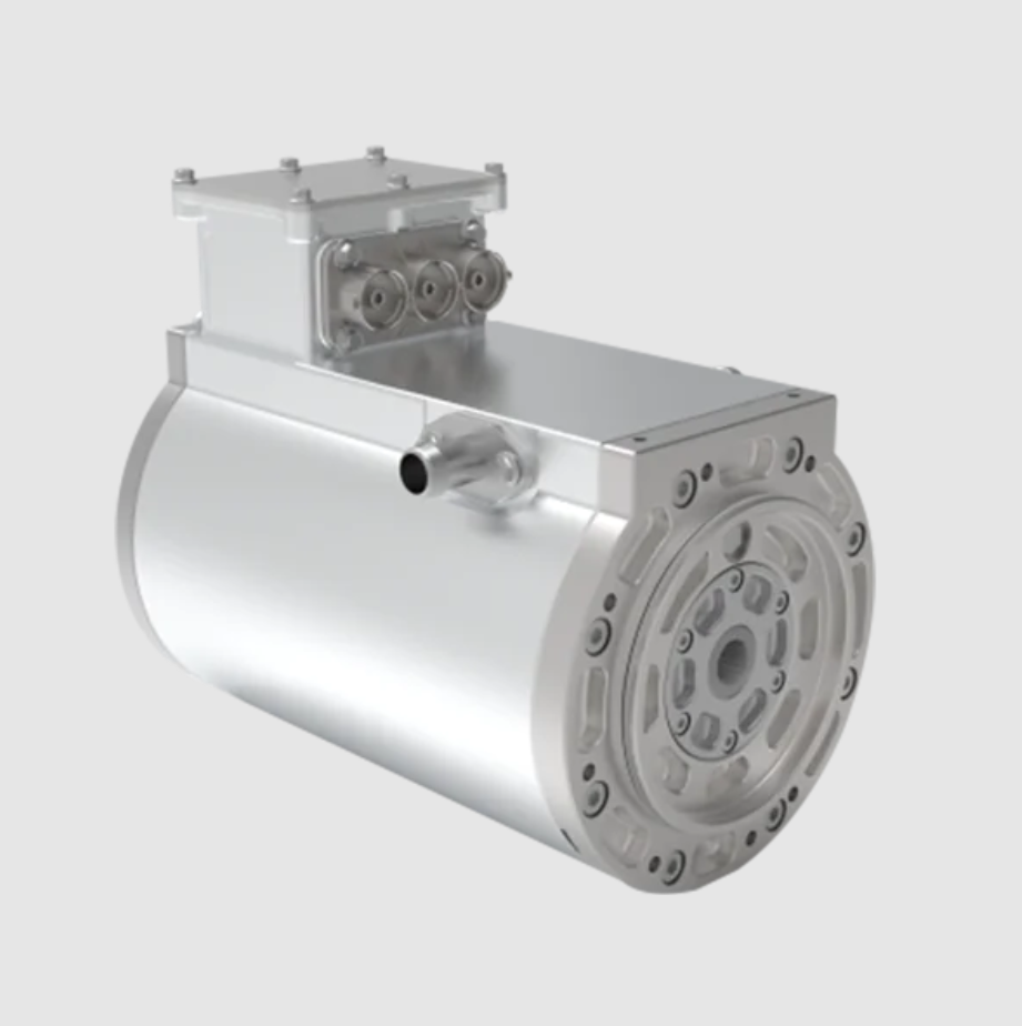
The physical configuration of the PMSM electric motor considered in this work is illustrated below.
For the bearing rotor speed control problem, I define the mechanical speed as the main state. Let \(x_1 = \omega_m\) and \(x_2 = \dot{\omega}_m\). From the mechanical motion equation, I obtain:
$$
\begin{aligned}
\dot{x}_1 &= x_2, \\
\dot{x}_2 &= \frac{1}{J} \left( \dot{T}_e – \dot{T}_L – B \dot{\omega}_m \right).
\end{aligned}
$$
Because the electromagnetic torque of the PMSM electric motor depends on the q-axis current and the d-axis current, and because these currents are regulated by the inner current loops, I can express the speed dynamics in a simplified input-output form for the outer speed loop:
$$
\dot{\omega}_m = f \left( \omega_m, t \right) + b_0 u,
$$
where \(f(\omega_m,t)\) represents the lumped uncertainty and external disturbance acting on the PMSM electric motor bearing rotor, \(b_0\) is the nominal control gain, and \(u\) is the control input, which is the q-axis current reference in my design. This form is suitable for active disturbance rejection control because the extended state observer can estimate \(f(\omega_m,t)\) as an additional state.
To make the model more explicit, I write the speed dynamics as:
$$
\begin{aligned}
\dot{x}_1 &= x_2, \\
\dot{x}_2 &= f(x_1,x_2,w,t) + b_0 u, \\
y &= x_1,
\end{aligned}
$$
where \(w\) denotes external load disturbance and parameter uncertainty. The term \(f(x_1,x_2,w,t)\) includes the nonlinear effects of the PMSM electric motor, the variation of \(J\), \(B\), \(\psi_f\), \(L_d\), \(L_q\), and \(R_s\), and the unknown load torque. In the active disturbance rejection control framework, I do not need to know \(f\) exactly. Instead, I estimate it in real time and compensate it in the control law.
Table 2 lists the parameters of the PMSM electric motor used in the experimental validation. These parameters are chosen to represent a high-speed PMSM electric motor suitable for traction and servo applications.
| Parameter | Symbol | Value | Unit |
|---|---|---|---|
| Rated power | \(P_N\) | 35 | kW |
| Rated speed | \(n_N\) | 4774 | r/min |
| Rated torque | \(T_N\) | 70 | N·m |
| Pole pairs | \(p\) | 4 | — |
| Stator resistance | \(R_s\) | 0.02 | Ω |
| Permanent magnet flux linkage | \(\psi_f\) | 0.175 | Wb |
| Moment of inertia | \(J\) | 0.003 | kg·m² |
| Viscous friction coefficient | \(B\) | 0.001 | N·m·s/rad |
3. Active Disturbance Rejection Control Design
The active disturbance rejection controller I design for the bearing rotor speed of the PMSM electric motor consists of three main parts: a tracking differentiator, an extended state observer, and a nonlinear state error feedback law. The overall structure is shown in the control block diagram. The tracking differentiator arranges the transition process for the desired speed and provides the differential signal. The extended state observer estimates the bearing rotor speed, its derivative, and the total disturbance. The nonlinear state error feedback law generates the preliminary control signal, and the estimated disturbance is compensated to produce the final control input. In this way, the active disturbance rejection control method actively rejects the influence of load disturbance and parameter variation on the PMSM electric motor bearing rotor speed.
3.1 Tracking Differentiator
The tracking differentiator is used to arrange the transient process of the desired bearing rotor speed of the PMSM electric motor. If the reference speed changes abruptly, a large initial error may cause overshoot or oscillation. The tracking differentiator smooths the reference and provides a differential signal that can be used in the nonlinear state error feedback law. I use the following discrete form:
$$
\begin{cases}
v_1(k+1) = v_1(k) + T_s v_2(k), \\[6pt]
v_2(k+1) = v_2(k) + T_s f_h \left( v_1(k) – v(k), v_2(k), r, h \right),
\end{cases}
$$
where \(v(k)\) is the desired bearing rotor speed of the PMSM electric motor, \(v_1(k)\) is the tracked reference speed, \(v_2(k)\) is the tracked derivative, \(T_s\) is the sampling period, \(r\) is the speed factor that determines the tracking speed, and \(h\) is the filtering factor that suppresses noise. The function \(f_h\) is the fastest control synthesis function. I use the following form:
$$
\begin{aligned}
d &= r h, \\
d_0 &= h d, \\
y &= v_1(k) – v(k) + h v_2(k), \\
a_0 &= \sqrt{d^2 + 8 r |y|}, \\
a &= \begin{cases}
v_2(k) + \dfrac{a_0 – d}{2} \operatorname{sgn}(y), & |y| \gt d_0, \\[8pt]
v_2(k) + \dfrac{y}{h}, & |y| \le d_0,
\end{cases} \\
f_h &= -\begin{cases}
r \operatorname{sgn}(a), & |a| \gt d, \\[6pt]
r \dfrac{a}{d}, & |a| \le d.
\end{cases}
\end{aligned}
$$
For the PMSM electric motor bearing rotor speed loop, the tracking differentiator prevents an abrupt setpoint from directly entering the controller. This is important because the bearing rotor of the PMSM electric motor has mechanical inertia and cannot follow an ideal step change without a transient. The tracking differentiator also reduces the noise amplification that would occur if the derivative of the reference were obtained by direct differentiation.
3.2 Extended State Observer
The extended state observer is the core of the active disturbance rejection control method. It estimates the states of the PMSM electric motor bearing rotor and the total disturbance. I design a second-order extended state observer for the speed dynamics. Let \(z_1\) be the estimate of the bearing rotor speed, \(z_2\) be the estimate of its derivative, and \(z_3\) be the estimate of the total disturbance. The discrete extended state observer is:
$$
\begin{cases}
e(k) = z_1(k) – y(k), \\[6pt]
z_1(k+1) = z_1(k) + T_s \left( z_2(k) – \beta_1 e(k) \right), \\[6pt]
z_2(k+1) = z_2(k) + T_s \left( z_3(k) – \beta_2 \operatorname{fal}(e(k), \alpha, \delta) + b_0 u(k) \right), \\[6pt]
z_3(k+1) = z_3(k) – T_s \beta_3 \operatorname{fal}(e(k), \alpha, \delta),
\end{cases}
$$
where \(y(k)\) is the measured bearing rotor speed of the PMSM electric motor, \(\beta_1\), \(\beta_2\), and \(\beta_3\) are observer gains, \(b_0\) is the nominal control gain, and \(\operatorname{fal}\) is a nonlinear function defined as:
$$
\operatorname{fal}(e, \alpha, \delta) =
\begin{cases}
|e|^\alpha \operatorname{sgn}(e), & |e| \gt \delta, \\[6pt]
\dfrac{e}{\delta^{1-\alpha}}, & |e| \le \delta.
\end{cases}
$$
The nonlinear function \(\operatorname{fal}\) provides a high gain for small errors and a lower gain for large errors, which helps the extended state observer achieve fast convergence without excessive oscillation. In the PMSM electric motor bearing rotor speed control, the extended state observer estimates not only the speed and acceleration but also the lumped disturbance caused by load torque, friction, parameter mismatch, and unmodeled dynamics. The estimated total disturbance \(z_3\) is then used for compensation.
The convergence of the extended state observer depends on the observer gains. I tune the gains according to the bandwidth of the PMSM electric motor speed loop. A common practice is to place the observer poles at \(-\omega_o\), where \(\omega_o\) is the observer bandwidth. For a third-order extended state observer, the gains can be chosen as:
$$
\beta_1 = 3 \omega_o, \quad \beta_2 = 3 \omega_o^2, \quad \beta_3 = \omega_o^3.
$$
However, because I use the nonlinear \(\operatorname{fal}\) function, the effective gains are adjusted according to the error magnitude. This makes the extended state observer more suitable for the PMSM electric motor bearing rotor speed control under wide operating conditions.
3.3 Nonlinear State Error Feedback
The nonlinear state error feedback law generates the preliminary control signal from the errors between the tracking differentiator outputs and the extended state observer estimates. I define the speed error and its derivative as:
$$
\begin{aligned}
e_1(k) &= v_1(k) – z_1(k), \\
e_2(k) &= v_2(k) – z_2(k).
\end{aligned}
$$
The preliminary control signal is:
$$
u_0(k) = k_1 \operatorname{fal}(e_1(k), \alpha_1, \delta) + k_2 \operatorname{fal}(e_2(k), \alpha_2, \delta),
$$
where \(k_1\) and \(k_2\) are the proportional and derivative gains of the nonlinear state error feedback law, and \(\alpha_1\) and \(\alpha_2\) are nonlinearity factors. The final control input is obtained by compensating the estimated total disturbance:
$$
u(k) = \frac{u_0(k) – z_3(k)}{b_0}.
$$
In the PMSM electric motor drive, \(u(k)\) is the q-axis current reference for the inner current loop. The inner current loop then regulates the actual q-axis current of the PMSM electric motor, which produces the electromagnetic torque and drives the bearing rotor. Because the extended state observer estimates the total disturbance, the nonlinear state error feedback law does not need to overcome the disturbance through a large gain. Instead, the disturbance is canceled by the compensation term \(-z_3(k)/b_0\). This is the key reason why the active disturbance rejection control method achieves strong anti-interference capability for the PMSM electric motor bearing rotor speed.
Table 3 summarizes the parameters of the active disturbance rejection controller used in my experiments. These parameters are selected by considering the bandwidth of the PMSM electric motor speed loop, the sampling period, and the desired transient response.
| Controller parameter | Symbol | Value |
|---|---|---|
| Sampling period | \(T_s\) | 0.0001 s |
| Tracking differentiator speed factor | \(r\) | 2500 |
| Tracking differentiator filtering factor | \(h\) | 0.001 |
| Observer bandwidth | \(\omega_o\) | 180 rad/s |
| Observer gain 1 | \(\beta_1\) | 540 |
| Observer gain 2 | \(\beta_2\) | 97200 |
| Observer gain 3 | \(\beta_3\) | 5832000 |
| Nonlinear factor | \(\alpha\) | 0.5 |
| Filtering factor in fal | \(\delta\) | 0.01 |
| Nonlinear state error feedback gain 1 | \(k_1\) | 35 |
| Nonlinear state error feedback gain 2 | \(k_2\) | 0.8 |
| Nominal control gain | \(b_0\) | 120 |
4. Stability and Parameter Tuning
For the bearing rotor speed control of the PMSM electric motor, stability is essential. I analyze the closed-loop system by considering the extended state observer and the nonlinear state error feedback law as a combined dynamic system. If the extended state observer converges, then \(z_3(k) \to f(x_1,x_2,w,t)\). Under this condition, the compensated plant becomes approximately a double-integrator system:
$$
\begin{aligned}
\dot{x}_1 &= x_2, \\
\dot{x}_2 &= b_0 u + f – z_3 \approx b_0 u.
\end{aligned}
$$
Then the nonlinear state error feedback law drives the tracking error to zero. In practice, the convergence rate depends on the observer bandwidth and the controller gains. I choose the observer bandwidth high enough to estimate the disturbance quickly, but not so high that measurement noise is amplified. I also choose the nonlinearity factors \(\alpha_1\) and \(\alpha_2\) to balance small-error sensitivity and large-error robustness.
I further consider the influence of parameter variation in the PMSM electric motor. If the stator resistance, inductance, or permanent magnet flux linkage changes, the electromagnetic torque production changes. The extended state observer treats this change as part of the total disturbance. Therefore, the active disturbance rejection control method reduces the sensitivity of the bearing rotor speed to parameter variation. This is an important advantage for the PMSM electric motor, because temperature and aging can significantly change the effective parameters in practical operation.
Table 4 shows the tuning guidelines I use for the active disturbance rejection controller of the PMSM electric motor bearing rotor speed.
| Tuning objective | Parameter | Effect of increasing the parameter |
|---|---|---|
| Faster reference tracking | \(r\) | Faster transition, but possible overshoot if too large. |
| Noise suppression in reference | \(h\) | Stronger filtering, but slower response. |
| Faster disturbance estimation | \(\omega_o\) | Faster convergence, but higher noise sensitivity. |
| Stronger proportional action | \(k_1\) | Faster error correction, but possible oscillation. |
| Stronger derivative action | \(k_2\) | Better damping, but sensitive to noise. |
| Nonlinear small-error behavior | \(\alpha\) | Smaller \(\alpha\) gives stronger nonlinearity near zero. |
5. Experimental Validation
I validate the proposed active disturbance rejection control method for the PMSM electric motor bearing rotor speed in a MATLAB/Simulink environment. I build the PMSM electric motor model using the available motor and power electronics blocks. The motor parameters are the same as those listed in Table 2. I set the desired bearing rotor speed to 1400 r/min and start the PMSM electric motor with no load. I record the speed response under the proposed method and under two comparison methods: a time-varying sliding mode control method and a fuzzy coupling control method. The comparison methods are selected because they represent two common advanced control approaches for the PMSM electric motor.
5.1 Speed Tracking Without Load
In the first test, the PMSM electric motor starts from standstill and tracks a desired bearing rotor speed of 1400 r/min. I record the speed control curves and evaluate the rise time, overshoot, settling time, and steady-state error. The qualitative behavior is clear: all three methods eventually reach the desired speed, but the proposed active disturbance rejection control method reaches the reference faster and with much smaller overshoot. The sliding mode method and the fuzzy coupling method exhibit slower dynamic response and noticeable oscillation before settling.
Table 5 presents the quantitative comparison for the no-load speed tracking test. The proposed method achieves the shortest rise time and settling time, the smallest overshoot, and the smallest steady-state error. These results confirm that the active disturbance rejection control method improves the dynamic response performance of the PMSM electric motor bearing rotor speed.
| Performance index | Proposed ADRC method | Sliding mode control | Fuzzy coupling control |
|---|---|---|---|
| Rise time to 90% of reference | 0.18 s | 0.31 s | 0.37 s |
| Overshoot | 0.6% | 4.8% | 5.7% |
| Settling time within ±1% | 0.26 s | 0.55 s | 0.68 s |
| Steady-state speed error | 0.4 r/min | 2.1 r/min | 2.8 r/min |
| Speed fluctuation after settling | 0.5 r/min | 3.2 r/min | 4.1 r/min |
The reason for this improvement is that the extended state observer estimates the total disturbance during startup, including the friction and the uncertainty in the electromagnetic torque. The nonlinear state error feedback law then generates a smooth control effort, and the compensation term prevents the integral-like error accumulation that often causes overshoot in conventional controllers. As a result, the PMSM electric motor bearing rotor speed follows the reference with a short transient and a stable steady state.
5.2 Load Disturbance Rejection
In the second test, I evaluate the anti-interference capability of the proposed method. The PMSM electric motor starts with no load and reaches the desired bearing rotor speed. At 4 s, I suddenly apply an additional load torque of 1.50 N·m to simulate an external load disturbance. I then record the speed response and the recovery time. A strong active disturbance rejection controller should quickly estimate the load disturbance and compensate it, so that the bearing rotor speed returns to the reference with minimal fluctuation.
Table 6 shows the disturbance rejection performance. The proposed method has the smallest maximum speed drop, the shortest recovery time, and the smallest speed fluctuation after the disturbance. The sliding mode control method and the fuzzy coupling control method both recover, but their recovery times are longer and their speed deviations are larger.
| Performance index under load disturbance | Proposed ADRC method | Sliding mode control | Fuzzy coupling control |
|---|---|---|---|
| Maximum speed drop | 12 r/min | 38 r/min | 45 r/min |
| Recovery time to ±1% band | 0.21 s | 0.62 s | 0.78 s |
| Post-disturbance fluctuation | 3 r/min | 14 r/min | 18 r/min |
| Steady-state error after recovery | 0.5 r/min | 2.5 r/min | 3.0 r/min |
These results demonstrate that the active disturbance rejection control method provides excellent anti-interference capability for the PMSM electric motor bearing rotor speed. The extended state observer treats the sudden load torque as part of the total disturbance and estimates it within a short time. The nonlinear state error feedback law then adjusts the q-axis current reference, and the compensation term cancels the disturbance. This allows the PMSM electric motor to restore the bearing rotor speed quickly and smoothly.
5.3 Robustness Under Parameter Variation
I further test the robustness of the proposed method under parameter variation. In a practical PMSM electric motor, the stator resistance changes with temperature, the permanent magnet flux linkage may decrease due to aging, and the inductances may vary with operating point. To simulate these effects, I change the stator resistance by ±20%, the permanent magnet flux linkage by ±10%, and the moment of inertia by ±15%. I then repeat the speed tracking and load disturbance tests.
Table 7 summarizes the robustness results. The proposed active disturbance rejection control method maintains good speed tracking performance under all tested parameter variations. The maximum speed error remains small, and the recovery time after load disturbance does not increase significantly. In contrast, the sliding mode control method and the fuzzy coupling control method show larger performance degradation, especially when the permanent magnet flux linkage and the moment of inertia change.
| Parameter variation | Proposed ADRC maximum speed error | Sliding mode maximum speed error | Fuzzy coupling maximum speed error |
|---|---|---|---|
| \(R_s\) +20% | 0.8 r/min | 3.4 r/min | 4.0 r/min |
| \(R_s\) −20% | 0.7 r/min | 3.1 r/min | 3.8 r/min |
| \(\psi_f\) +10% | 0.9 r/min | 4.2 r/min | 5.1 r/min |
| \(\psi_f\) −10% | 1.0 r/min | 4.8 r/min | 5.6 r/min |
| \(J\) +15% | 1.1 r/min | 5.0 r/min | 6.2 r/min |
| \(J\) −15% | 1.2 r/min | 5.5 r/min | 6.8 r/min |
The robustness of the proposed method comes from the extended state observer. Because the observer estimates the lumped disturbance, it does not rely on an exact model of the PMSM electric motor. When the parameters change, the resulting torque error is treated as part of the total disturbance. The nonlinear state error feedback law then compensates this error, and the bearing rotor speed remains close to the reference. This is a major advantage for the PMSM electric motor in applications where operating conditions vary widely.
6. Discussion
The results show that the proposed active disturbance rejection control method is effective for the bearing rotor speed control of the PMSM electric motor. Compared with the sliding mode control method, the proposed method does not require a detailed sliding surface design or a time-varying switching gain. Compared with the fuzzy coupling control method, the proposed method is less sensitive to parameter changes because the extended state observer explicitly estimates and compensates the total disturbance. The control structure is also modular: the tracking differentiator, extended state observer, and nonlinear state error feedback law can be tuned separately.
The key advantage of the proposed method is that it treats the PMSM electric motor bearing rotor speed loop as an uncertain system and actively rejects the disturbance. This is important because the load torque, friction, and parameter variation are difficult to model precisely. The extended state observer provides an estimate of the total disturbance, and the nonlinear state error feedback law provides the control action. The compensation term then cancels the disturbance, so the PMSM electric motor behaves approximately like a nominal double-integrator system. This explains why the proposed method achieves fast dynamic response and strong anti-interference capability.
From an implementation perspective, the proposed method is suitable for digital control of the PMSM electric motor. The tracking differentiator, extended state observer, and nonlinear state error feedback law are all expressed in discrete form, so they can be implemented in a digital signal processor or microcontroller. The computational burden is modest, and the method does not require additional sensors beyond the speed and current measurements usually available in a PMSM electric motor drive. This makes the proposed method attractive for practical applications.
There are also limitations. The performance of the active disturbance rejection control method depends on the observer bandwidth and the controller gains. If the observer bandwidth is too high, measurement noise may be amplified. If the observer bandwidth is too low, the disturbance estimation may be slow. Therefore, careful tuning is required. In future work, I plan to investigate adaptive tuning of the observer bandwidth and the nonlinear state error feedback gains for the PMSM electric motor. I also plan to test the proposed method on a hardware platform with a real PMSM electric motor and a programmable load.
7. Conclusion
I have proposed an active disturbance rejection control method for the bearing rotor speed of a PMSM electric motor. I constructed a mathematical model of the PMSM electric motor in the d-q coordinate frame, including the voltage equations, the electromagnetic torque equation, and the mechanical motion equation. I designed a controller composed of a tracking differentiator, an extended state observer, and a nonlinear state error feedback law. The tracking differentiator arranges the transient profile of the desired speed. The extended state observer estimates the bearing rotor speed, its derivative, and the total disturbance. The nonlinear state error feedback law generates the preliminary control signal, and the estimated disturbance is compensated to produce the final q-axis current reference.
I validated the proposed method in a MATLAB/Simulink environment using a high-speed PMSM electric motor model. The experimental results show that the proposed method achieves faster speed tracking, smaller overshoot, shorter settling time, and smaller steady-state error than a sliding mode control method and a fuzzy coupling control method. Under a sudden load disturbance, the proposed method has the smallest maximum speed drop and the shortest recovery time. Under parameter variation, the proposed method maintains good robustness. These results confirm that the active disturbance rejection control method significantly improves the dynamic response performance and anti-interference capability of the PMSM electric motor bearing rotor speed control.
The proposed method provides a practical solution for the PMSM electric motor in electric vehicles, aerospace systems, and high-speed traction applications. Because the method does not require an exact model and can estimate the total disturbance in real time, it is well suited to the uncertain operating conditions of the PMSM electric motor. I believe that the active disturbance rejection control method will continue to play an important role in the advanced control of the PMSM electric motor bearing rotor speed.