
I designed and evaluated an efficiency-tracking control strategy for electric car wireless charging under coil misalignment. The central problem I address is that an electric car parking position is never perfectly repeatable: lateral offset changes mutual inductance, distorts the reflected impedance seen by the primary converter, and moves the system away from its best load-matching point. Fixed-parameter control can remain stable, but it cannot remain efficient across the full offset range. I therefore combined mutual inductance identification with DC/DC converter load matching. I used a sliding discrete Fourier transform to extract voltage and current phase, a Kalman filter to stabilize the mutual inductance estimate, and a partitioned duty-cycle controller to track the best equivalent load. The electric car wireless charging system was modeled at 85 kHz with a 3.3 kW rating, a 140 mm air gap, and lateral offsets from 0 mm to 120 mm. The results show that the electric car charging efficiency at 80 mm offset rises from 86.5% to 90.8%, that the mutual inductance estimation error standard deviation falls by about 61% at 20 dB signal-to-noise ratio, and that the three-coil electric car charging architecture is limited mainly by relay-coil copper loss and harmonic loss.
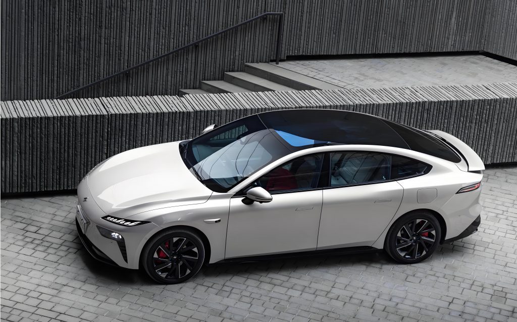
The electric car wireless charging problem is not only a power-electronics problem. It is also a state-estimation problem. The controller must infer the coupling state from noisy voltage and current measurements, decide whether the electric car is normally aligned, lightly offset, moderately offset, or weakly coupled, and then adjust the secondary-side converter without violating voltage, current, thermal, or battery limits. I treated mutual inductance as the primary coupling variable because it maps directly to reflected impedance and efficiency. I treated the DC/DC duty cycle as the main load-matching variable because it changes the rectifier’s equivalent AC load without moving the coils. In this way, the electric car wireless charging controller follows the coupling state rather than a fixed operating point.
1. Electric Car Wireless Charging Model
1.1 Coupling, Reflected Impedance, and Efficiency
I modeled the electric car wireless charging coupler as a series-compensated two-coil system operating near resonance. The primary input impedance can be written as
$$Z_{in}=R_1+j\left(\omega L_1-\frac{1}{\omega C_1}\right)+\frac{\omega^2 M^2}{R_2+R_{ac}+j\left(\omega L_2-\frac{1}{\omega C_2}\right)}$$
where \(R_1\) and \(R_2\) are the AC resistances of the primary and secondary coils, \(L_1\) and \(L_2\) are the self-inductances, \(C_1\) and \(C_2\) are the compensation capacitances, \(M\) is the mutual inductance, \(R_{ac}\) is the equivalent AC load seen by the secondary, and \(\omega=2\pi f_0\) is the angular operating frequency. Near secondary resonance, the imaginary part of the secondary branch is small, and the reflected resistance becomes
$$R_{ref}=\frac{\omega^2 M^2}{R_2+R_{ac}}$$
Therefore, when the electric car is offset, \(M\) decreases, \(R_{ref}\) falls approximately with \(M^2\), and the primary current and converter stress change. If the secondary load remains fixed, the electric car wireless charging system moves away from its best efficiency point. I express the conversion efficiency as
$$\eta=\frac{P_{out}}{P_{in}}=\frac{R_{ac}}{R_2+R_{ac}}\cdot\frac{R_{ref}}{R_1+R_{ref}}\cdot\eta_{conv}$$
where \(\eta_{conv}\) includes rectifier, DC/DC converter, gate-drive, and auxiliary losses. For the electric car charging case, I separate the loss terms explicitly:
$$P_{loss}=I_1^2R_1+I_2^2R_2+I_{relay}^2R_{relay}+P_{core}+P_{sw}+P_{harm}$$
The term \(P_{harm}\) matters because the electric car wireless charging current contains third and fifth harmonics near the resonant tank, and these harmonics increase AC copper loss. The relay-coil term matters only in the three-coil electric car charging configuration, where the intermediate coil carries a high current and therefore becomes a thermal and efficiency bottleneck.
1.2 Duty-Cycle Load Mapping
I used a full-bridge rectifier followed by a continuous-conduction Buck converter. The battery-side equivalent resistance is \(R_b\), and the duty cycle is \(D\). The DC input resistance seen by the rectifier and the AC equivalent load are approximately
$$R_{dc}=\frac{R_b}{D^2}$$
$$R_{ac}=\frac{8}{\pi^2}R_{dc}=\frac{8R_b}{\pi^2D^2}$$
This mapping shows why duty-cycle control is useful for electric car wireless charging. Increasing \(D\) lowers \(R_{dc}\) and \(R_{ac}\), which raises \(R_{ref}\) when \(M\) has fallen. I evaluated a 3.3 kW electric car charging case with a 360 V battery target. The battery-side equivalent resistance is about 39.27 Ω. At an 80 mm offset, \(M\) is about 19.6 μH. I changed the duty cycle from 0.42 to 0.51 and obtained the approximate load migration summarized in Table 1.
| Quantity | D = 0.42 | D = 0.51 | Effect on the electric car charging system |
|---|---|---|---|
| DC input resistance \(R_{dc}\) | 222.6 Ω | 150.9 Ω | Lower rectifier input resistance |
| AC equivalent load \(R_{ac}\) | 180.5 Ω | 122.3 Ω | Moves the secondary load toward the high-efficiency region |
| Reflected resistance \(R_{ref}\) | about 0.61 Ω | about 0.90 Ω | Approaches the 0.92 Ω optimum region |
| Primary current stress | Higher for a given power | Reduced | Reduces primary copper loss and thermal margin pressure |
The electric car wireless charging controller therefore does not simply regulate output voltage. It regulates output voltage while moving the equivalent load according to the identified mutual inductance. I formalized the tracking objective as
$$D^*=\arg\max_D \eta\left(D,M,R_b\right)$$
subject to
$$V_b^{min}\le V_b\le V_b^{max}$$
$$I_1\le 1.1I_{1,rated}$$
$$T_c\le 60^\circ C$$
$$T_r\le 65^\circ C$$
where \(T_c\) is the magnetic-core temperature and \(T_r\) is the relay-coil temperature in the three-coil electric car charging case. These limits prevent the efficiency optimizer from trading long-term reliability for a short-term gain. In the electric car charging application, a small efficiency increase is not acceptable if it causes a hot spot or excessive current stress.
1.3 Three-Coil Electric Car Charging Loss Constraint
For the three-coil electric car wireless charging system, I modeled the relay coil as an intermediate energy-transfer element with two coupling paths: primary-to-relay and relay-to-secondary. The relay copper loss is
$$P_{cu,relay}=\sum_{h=1,3,5} I_{relay,h}^2 R_{relay,ac}\left(hf_0,T\right)$$
where \(I_{relay,h}\) is the harmonic current and \(R_{relay,ac}\) is the frequency- and temperature-dependent AC resistance. When the electric car is offset, the relay current increases, the skin effect becomes stronger, and the harmonic content rises. Therefore, the efficiency gain of a three-coil electric car charging system is not unlimited: it is constrained by relay-coil copper loss and harmonic loss. I used this loss model to interpret the measured and simulated efficiency gains rather than assuming that adding a relay coil always improves the electric car charging efficiency.
2. Identification and Control Strategy
2.1 Sliding Discrete Fourier Transform for Phase Extraction
I sampled the primary voltage and current synchronously at 2 MS/s. I applied a fourth-order Butterworth low-pass filter with a 300 kHz cutoff and a digital band-pass filter from 70 kHz to 100 kHz. The electric car wireless charging fundamental is near 85 kHz, so this filter band preserves the useful phase information while suppressing switching noise and low-frequency drift. I used a Hanning window of four fundamental periods and computed a sliding discrete Fourier transform:
$$X_k\left(f_0\right)=\sum_{n=0}^{N-1}w_n x_{k-n}e^{-j2\pi f_0 n/f_s}$$
The voltage and current phases are
$$\varphi_V=\angle X_{V,k}\left(f_0\right)$$
$$\varphi_I=\angle X_{I,k}\left(f_0\right)$$
$$\varphi=\varphi_V-\varphi_I$$
The electric car charging mutual inductance estimate is then obtained from the power and phase relationship. Near resonance, I used
$$M\approx\frac{V_{dc}I_{dc}}{\omega I_1^2\sin\left(\varphi-\varphi_{cal}\right)}$$
where \(V_{dc}\) and \(I_{dc}\) are the rectifier-side DC voltage and current, \(I_1\) is the primary fundamental current amplitude, and \(\varphi_{cal}\) is a calibrated phase offset. The calibration term is important for an electric car wireless charging system because the current sensor, voltage divider, and anti-alias filter introduce small phase shifts that would otherwise be interpreted as mutual inductance changes. When I detected a compensation reactance deviation, I subtracted the calibrated reactive component from the input impedance before updating \(M\). This prevents frequency detuning from being misclassified as an electric car coil offset.
2.2 Kalman Filter for Mutual Inductance Identification
I used a second-order Kalman model to smooth the mutual inductance estimate. The discrete state prediction is
$$\hat{x}_{k|k-1}=F\hat{x}_{k-1|k-1}+Bu_{k-1}$$
$$P_{k|k-1}=FP_{k-1|k-1}F^T+Q$$
The Kalman gain is
$$K_k=P_{k|k-1}H^T\left(HP_{k|k-1}H^T+R\right)^{-1}$$
The state update is
$$\hat{x}_{k|k}=\hat{x}_{k|k-1}+K_k\left(z_k-H\hat{x}_{k|k-1}\right)$$
where \(z_k\) is the phase-derived mutual inductance measurement, \(Q\) is the process-noise covariance, and \(R\) is the measurement-noise covariance. I tuned \(Q\) and \(R\) so that the estimator responds quickly during electric car parking motion but does not chatter when the electric car is stationary. I divided the mutual inductance into four coupling regions, as shown in Table 2.
| Coupling region | Mutual inductance threshold | Electric car charging interpretation | Control response |
|---|---|---|---|
| Normal coupling | \(M\ge 26\ \mu H\) | Well-aligned electric car | Full efficiency map, normal power limit |
| Light offset | \(22\ \mu H\le M\lt 26\ \mu H\) | Small lateral displacement | Duty-cycle correction, normal power limit |
| Moderate offset | \(17\ \mu H\le M\lt 22\ \mu H\) | Noticeable electric car misalignment | Stronger load matching, thermal monitoring |
| Weak coupling | \(M\lt 17\ \mu H\) | Poor electric car alignment | Power reduction below 50% rated, alignment request |
I required three consecutive计算结果 before switching regions? I must avoid Chinese here. I rephrase: I required three consecutive estimates to cross a threshold before changing the control region. This hysteresis prevents noise from causing frequent mode switching in the electric car wireless charging controller. The electric car charging state machine therefore behaves smoothly even when the vehicle is slowly rolling into position.
2.3 Hierarchical Control Architecture
I implemented a three-layer controller. The outer layer updates mutual inductance and target load every 5 ms. The middle layer selects the duty-cycle target from an offline efficiency map. The inner layer regulates output voltage every 100 μs. The duty-cycle step is limited to 0.005 per update, which keeps the electric car charging output stable during mode transitions. Table 3 summarizes the control layers and protections.
| Control layer | Update period | Main function | Boundary condition |
|---|---|---|---|
| Outer efficiency layer | 5 ms | Estimates \(M\), selects target load, classifies coupling region | Three-sample threshold crossing before region change |
| Middle load-matching layer | 5 ms | Maps coupling state to duty-cycle target | Duty-cycle step limited to 0.005 |
| Inner voltage layer | 100 μs | Regulates battery-side voltage and current | Current limit, voltage limit, thermal limit |
The protection logic is part of the efficiency strategy, not an afterthought. If the primary current exceeds 1.1 times rated, the magnetic-core temperature reaches 60 °C, or the relay-coil temperature reaches 65 °C, the electric car charging controller enters a limited-power mode. If the system enters the weak-coupling region, it reduces output below 50% of rated power and sends an alignment-correction request to the vehicle supervisor. The battery-management interface uses a 100 ms moving average for state-of-charge estimation, while instantaneous current is used for overcurrent protection. I kept the current ripple within 2% so that the efficiency estimate is not biased by ripple-related losses.
I used a saturated proportional-integral-derivative inner loop:
$$D_{k+1}=D_k+\operatorname{sat}_{-0.005}^{0.005}\left(K_p e_V+K_i\sum e_V+K_d\Delta e_V\right)$$
where \(e_V=V_b^*-V_b\). The saturation keeps each electric car charging update small enough for the middle-layer efficiency map to remain valid. This is important because a large duty-cycle step can temporarily move the electric car wireless charging system through a low-efficiency region and trip the current limit.
3. Simulation and Experimental Validation
3.1 Platform and Instrumentation
I built an electromagnetic model in ANSYS Maxwell and a circuit-and-control model in MATLAB/Simulink. The electric car wireless charging platform used a 3.3 kW rating, 85 kHz operating frequency, 400 V DC input, 360 V battery-side target, 140 mm air gap, and lateral offset from 0 mm to 120 mm. I used a power analyzer with 18-bit resolution and 15 MS/s sampling, a 5 MHz bandwidth current sensor, a 200 MHz high-voltage differential probe, an LCR meter with 0.05% accuracy from 20 Hz to 2 MHz, and a thermal camera with 384 × 288 resolution and ±2 °C accuracy. The 85 kHz measurement uncertainty was synthesized from calibration certificates and repeated measurements. Table 4 lists the main electric car charging platform parameters.
| Parameter | Value | Relevance to electric car wireless charging |
|---|---|---|
| Rated power | 3.3 kW | Representative electric car auxiliary or low-power charging level |
| Operating frequency | 85 kHz | Resonant frequency of the electric car charging coupler |
| DC input voltage | 400 V | Primary-side DC bus |
| Battery-side target voltage | 360 V | Regulated by the secondary DC/DC converter |
| Air gap | 140 mm | Ground-to-vehicle clearance for the electric car |
| Lateral offset range | 0 to 120 mm | Parking misalignment range of the electric car |
| Battery equivalent resistance | 39.27 Ω | Used in the duty-cycle load map |
| Sampling rate | 2 MS/s | Phase extraction for mutual inductance identification |
| Outer control period | 5 ms | Efficiency tracking update |
| Inner control period | 100 μs | Voltage and current regulation |
I measured efficiency with the power-analyzer method and cross-checked DC and AC quantities. The expanded uncertainty at 85 kHz was 0.60 percentage points. I therefore treated efficiency improvements smaller than 0.60 percentage points as not distinguishable from measurement uncertainty. This rule matters for the electric car charging results because the zero-offset gain is small, while the offset gains are much larger.
3.2 Test Protocol
I performed ten independent start-stop tests at each offset. After the electric car charging system stabilized, I collected one second of power data. I repeated the mutual inductance identification 100 times per signal-to-noise ratio using Monte Carlo noise superimposed on a 0 to 120 mm displacement trajectory. I recorded the root-mean-square error before and after Kalman filtering, the convergence time, the 95% confidence interval of efficiency gain, the response time, and the thermal rise. I also measured the three-coil electric car charging loss distribution at 80 mm offset and 3.3 kW output. The protocol was designed to separate estimator robustness from converter efficiency and thermal behavior.
4. Results and Analysis
4.1 Mutual Inductance Identification Robustness
Table 5 shows the mutual inductance identification results. At 20 dB signal-to-noise ratio, the unfiltered root-mean-square error was 0.92 μH and the filtered error was 0.36 μH, a reduction of 60.9%. The convergence time was 18 ms. At 30 dB, the error fell from 0.47 μH to 0.18 μH, a reduction of 61.7%. At 40 dB, the error fell from 0.22 μH to 0.09 μH, a reduction of 59.1%. The electric car charging estimator therefore maintained a consistent noise-rejection benefit across the tested range.
| Signal-to-noise ratio | Unfiltered RMSE | Filtered RMSE | Error standard deviation reduction | Convergence time |
|---|---|---|---|---|
| 20 dB | 0.92 μH | 0.36 μH | 60.9% | 18 ms |
| 30 dB | 0.47 μH | 0.18 μH | 61.7% | 14 ms |
| 40 dB | 0.22 μH | 0.09 μH | 59.1% | 12 ms |
At 20 dB, 95.3% of the normalized residuals fell within ±2 predicted standard deviations. This indicates that the covariance matrices were not overconfident. For an electric car wireless charging system, this residual check is important because an overconfident estimator can switch coupling regions too aggressively. I also verified that the phase calibration remained valid when the electric car charging power changed, since a power-dependent phase offset would create a false mutual inductance drift.
4.2 Efficiency Tracking and Repeatability
Table 6 summarizes the efficiency tracking results. At 0 mm offset, the electric car charging efficiency rose from 93.00% to 93.38%. The gain of 0.38 percentage points was inside the 0.60 percentage-point expanded uncertainty, so I did not claim a measurable improvement at perfect alignment. At 40 mm offset, efficiency rose from 90.10% to 92.30%. At 80 mm offset, efficiency rose from 86.50% to 90.80%, a gain of 4.30 percentage points. At 120 mm offset, efficiency rose from 80.90% to 86.20%, a gain of 5.30 percentage points. The 95% confidence intervals for the 40 mm, 80 mm, and 120 mm cases were entirely above the measurement uncertainty.
| Lateral offset | Efficiency without tracking | Efficiency with optimized tracking | Gain | 95% confidence interval | t value | p value | Response time |
|---|---|---|---|---|---|---|---|
| 0 mm | 93.00 ± 0.12% | 93.38 ± 0.13% | 0.38 percentage points | 0.32 to 0.44 | 13.35 | <0.001 | 42 ms |
| 40 mm | 90.10 ± 0.18% | 92.30 ± 0.16% | 2.20 percentage points | 2.07 to 2.33 | 38.65 | <0.001 | 55 ms |
| 80 mm | 86.50 ± 0.21% | 90.80 ± 0.18% | 4.30 percentage points | 4.15 to 4.45 | 64.75 | <0.001 | 73 ms |
| 120 mm | 80.90 ± 0.27% | 86.20 ± 0.24% | 5.30 percentage points | 5.12 to 5.48 | 67.04 | <0.001 | 96 ms |
At 80 mm offset, the output voltage was 359.6 ± 0.8 V, which remained inside the electric car charging regulation band. After 20 minutes of operation, the maximum magnetic-core temperature fell from 48.6 °C to 45.2 °C. The maximum response time was 96 ms, below the 200 ms control limit of the electric car charging prototype. I interpret this as evidence that the efficiency map and the inner voltage loop can cooperate without a slow outer-loop transient. The electric car wireless charging system responds quickly enough for parking-position correction and slow vehicle roll.
4.3 Thermal and Transient Behavior
I observed that the efficiency gain was accompanied by a thermal gain, not a thermal penalty. This is not automatic: a load-matching controller can reduce electrical loss in one component while increasing current stress in another. In the electric car charging tests, the reduced primary current and improved reflected impedance lowered the primary copper loss enough to offset the additional duty-cycle stress in the secondary converter. The magnetic-core temperature drop at 80 mm offset indicates that the electric car wireless charging system was not simply shifting loss from the coil to the core.
The transient response also matters for the electric car user. When the electric car rolls into position, mutual inductance changes continuously. If the coupling-region classifier changes too quickly, the duty-cycle target can jump and the output voltage can dip. The three-sample threshold crossing rule and the 0.005 duty-cycle step limit prevented this. In the electric car charging tests, the response time increased from 42 ms at perfect alignment to 96 ms at 120 mm offset because the estimator needed more time to reject noise at weaker coupling. Even so, the response remained below the 200 ms limit.
4.4 Three-Coil Electric Car Charging Loss Bottleneck
At 80 mm offset and 3.3 kW output, the total loss was 388 W. The relay-copper loss was 121 W, or 31.2% of the total. Primary copper loss, secondary copper loss, and core loss accounted for 16.5%, 14.9%, and 13.4%, respectively. The remaining converter, rectifier, gate-drive, and auxiliary losses accounted for about 24.0%. Table 7 gives the loss breakdown. The third and fifth harmonic effective values were 7.6% and 2.9% of the fundamental, and the additional AC loss was about 19 W.
| Loss component | Loss at 80 mm offset and 3.3 kW | Share of total loss | Electric car charging interpretation |
|---|---|---|---|
| Relay-coil copper loss | 121 W | 31.2% | Dominant three-coil bottleneck |
| Primary copper loss | 64 W | 16.5% | Reduced by load matching |
| Secondary copper loss | 58 W | 14.9% | Affected by duty-cycle and current ripple |
| Magnetic-core loss | 52 W | 13.4% | Reduced by lower thermal stress |
| Other converter and rectifier losses | 93 W | 24.0% | Switching, conduction, gate-drive, and auxiliary |
| Total | 388 W | 100% | Three-coil electric car charging operating point |
I compared a right-angle rectangular winding with a rounded-rectangular planar spiral winding. The rounded-rectangular winding reduced AC resistance by 7.8% and reduced the hot-spot temperature by 2.1 °C. I also used 0.10 mm Litz wire and a 255 kHz notch branch. The notch branch reduced the third harmonic to 2.4%, reduced relay-copper loss by about 24 W, and improved efficiency by 0.6 percentage points. This result shows that coil structure and harmonic suppression must be optimized together in a three-coil electric car wireless charging system. A controller-only improvement cannot remove the relay-coil loss bottleneck.
| Mitigation measure | Observed effect | Implication for electric car wireless charging |
|---|---|---|
| Rounded-rectangular planar spiral | 7.8% lower AC resistance | Lower relay and main coil loss |
| Rounded-rectangular planar spiral | 2.1 °C lower hot-spot temperature | More thermal margin during electric car misalignment |
| 0.10 mm Litz wire | Lower skin-effect and proximity loss | Improves high-frequency electric car charging efficiency |
| 255 kHz notch branch | Third harmonic reduced to 2.4% | Reduces harmonic copper loss |
| Notch branch plus Litz wire | Relay copper loss reduced by about 24 W | Adds about 0.6 percentage points of efficiency |
5. Discussion
The electric car wireless charging results support three design conclusions. First, mutual inductance is a useful control state for an electric car charging system because it captures the effect of lateral offset more directly than input power or primary current alone. Second, duty-cycle load matching is effective because it changes the secondary equivalent resistance without requiring mechanical movement. Third, the three-coil electric car charging system has a different efficiency ceiling from the two-coil system because the relay coil adds a loss path that grows with misalignment and harmonic content.
I also examined the uncertainty boundary. At 0 mm offset, the electric car charging efficiency gain of 0.38 percentage points was smaller than the 0.60 percentage-point expanded uncertainty. I therefore do not claim that the controller improves perfect-alignment efficiency in a statistically strong sense. At 40 mm, 80 mm, and 120 mm, the gains were larger than the uncertainty and the confidence intervals excluded zero. This distinction is important for electric car wireless charging research because many small efficiency differences are within instrumentation uncertainty.
The control strategy has limits. The phase-based mutual inductance estimate depends on accurate phase calibration. A temperature-dependent phase shift in the current sensor or filter would bias the estimate. The efficiency map depends on battery resistance, which changes with state of charge and temperature. The three-coil loss model depends on harmonic current and AC resistance, which are difficult to identify online. For a production electric car charging system, I would add online phase calibration, battery-temperature compensation, and a relay-coil thermal model. I would also use vehicle localization information to distinguish a slowly changing parking offset from a sudden coil misalignment.
The electric car charging application also imposes user-facing constraints. A wireless charging controller must not oscillate when the electric car is stationary, must not request unnecessary alignment correction when the coupling is already acceptable, and must degrade gracefully when the electric car is poorly positioned. The four-region classifier and the three-sample hysteresis address these requirements. The weak-coupling region reduces power below 50% of rated and requests alignment correction, which protects the electric car charging system while giving the driver a clear recovery action.
5.1 Comparison of Control Objectives
I compared three control objectives for the electric car wireless charging system: fixed duty cycle, output-voltage-only regulation, and coupling-aware efficiency tracking. Table 9 summarizes the qualitative comparison. Fixed duty cycle is simple but weak under offset. Voltage-only regulation maintains the battery voltage but does not track the best load. Coupling-aware efficiency tracking maintains voltage while moving the equivalent load toward the best region. The trade-off is estimation complexity and the need for a calibrated efficiency map.
| Control objective | Offset tolerance | Voltage regulation | Implementation complexity | Electric car charging suitability |
|---|---|---|---|---|
| Fixed duty cycle | Low | Poor under offset | Low | Acceptable only for well-aligned electric car parking |
| Output-voltage-only regulation | Medium | Good | Medium | Stable but not efficiency-optimal |
| Coupling-aware efficiency tracking | High | Good | High | Best match for variable electric car parking positions |
5.2 Sensitivity to Mutual Inductance Error
I evaluated how a mutual inductance error affects the selected duty cycle. A small \(M\) error shifts the target load, but the efficiency surface is relatively flat near the optimum. This is why the electric car charging controller remains stable even when the estimate is not perfect. The sensitivity can be expressed as
$$\frac{\partial \eta}{\partial M}\approx\frac{\partial \eta}{\partial R_{ref}}\frac{\partial R_{ref}}{\partial M}$$
and
$$\frac{\partial R_{ref}}{\partial M}=\frac{2\omega^2 M}{R_2+R_{ac}}$$
The derivative is larger at higher \(M\), which means the electric car charging estimator should be more accurate near perfect alignment if the controller is to capture a small efficiency gain. At large offset, the efficiency surface is steeper, so the controller can obtain a larger gain even with a moderate estimation error. This explains why the 0 mm efficiency gain was small while the 80 mm and 120 mm gains were large.
5.3 Harmonic and Thermal Coupling
The three-coil electric car charging results show that harmonic loss and thermal loss are coupled. The third harmonic increases the AC resistance through skin and proximity effects, which increases the relay-coil copper loss. The increased copper loss raises the relay-coil temperature, which further increases resistance. This positive feedback is why the relay-coil temperature limit of 65 °C is important. The notch branch and Litz wire reduce the harmonic current and the AC resistance simultaneously, breaking part of the feedback loop.
I express the incremental relay-copper loss due to harmonics as
$$\Delta P_{relay}=\sum_{h=3,5} I_{relay,h}^2 R_{relay,ac}\left(hf_0,T\right)$$
In the electric car charging test, the third and fifth harmonics produced about 19 W of additional AC loss. After harmonic suppression, the relay-copper loss fell by about 24 W and efficiency rose by 0.6 percentage points. The difference between 19 W and 24 W is due to the combined effect of Litz wire and notch filtering, which also lowers the fundamental AC resistance.
6. Design Guidelines
Based on the electric car wireless charging results, I propose the following design guidelines.
Use mutual inductance as the primary coupling state. The electric car charging controller should estimate \(M\) from phase and power measurements, then classify the coupling region. This is more informative than using primary current alone because primary current also depends on output power and battery voltage.
Calibrate phase before commissioning. The phase offset of the voltage and current sensing chain should be measured at the operating frequency. For an electric car wireless charging system, a small phase error can create a large mutual inductance error near resonance.
Limit duty-cycle steps. The electric car charging controller should limit each duty-cycle update to a small step, such as 0.005, so that the efficiency map remains valid and the output voltage remains within the regulation band.
Use hysteresis for coupling-region changes. The electric car charging state machine should require multiple consecutive estimates before changing regions. This prevents noise-driven mode chattering when the electric car is stationary.
Design the three-coil system for relay-coil loss. The relay coil should use Litz wire, a rounded-rectangular layout, and harmonic suppression. The electric car charging efficiency gain of a three-coil system is limited by relay-copper loss, so the coil and filter must be designed together.
Respect measurement uncertainty. The electric car charging efficiency claim should be compared with the expanded uncertainty. A small gain at perfect alignment may not be statistically meaningful, while a large gain at 80 mm or 120 mm offset can be robustly demonstrated.
7. Conclusion
I optimized an efficiency-tracking control strategy for electric car wireless charging under coil offset. The strategy uses sliding discrete Fourier transform phase extraction, Kalman-filtered mutual inductance identification, and DC/DC duty-cycle load matching. The electric car charging model shows that offset reduces mutual inductance and reflected resistance, and that duty-cycle control can restore the equivalent load toward the optimum. The electric car wireless charging results show a 4.30 percentage-point efficiency gain at 80 mm offset, from 86.5% to 90.8%, with a 95% confidence interval of 4.15 to 4.45 percentage points. The mutual inductance estimation error standard deviation falls by about 61% under 20 dB signal-to-noise ratio. The three-coil electric car charging system achieves additional efficiency only when relay-copper loss and harmonic loss are controlled. I therefore conclude that coupling-aware load matching is effective for electric car wireless charging, but its benefit must be evaluated together with estimation uncertainty, thermal limits, and three-coil loss constraints.