
In this article, I examine the drive control technologies that shape the performance, reliability, and industrial reach of the high-speed permanent magnet synchronous motor. I focus on the high-speed permanent magnet synchronous motor because its high efficiency, high power density, and favorable torque-to-inertia ratio make it attractive for aerospace systems, robotic joints, electric vehicles, high-speed spindles, compressors, and precision motion platforms. From my perspective, the central difficulty is not merely obtaining rotation at high speed. The real challenge is maintaining stable speed tracking, low torque ripple, low current harmonic distortion, robust fault behavior, and acceptable thermal and electromagnetic stress at the same time. I therefore organize the discussion around drive architecture, sensorless vector control, space vector pulse width modulation, direct torque control, current hysteresis proportional-integral control, high-speed operation mechanisms, fault-tolerant design, and a proposed composite vector control strategy based on space vector pulse width modulation.
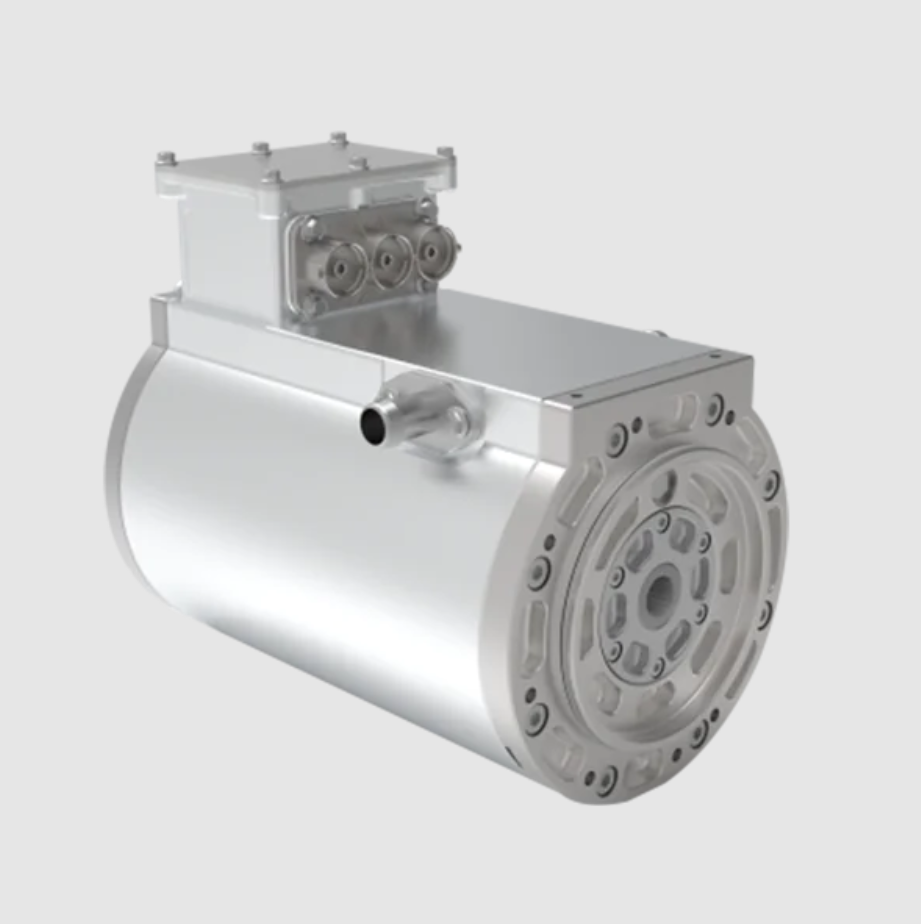
Drive System Perspective
I view the high-speed permanent magnet synchronous motor drive system as a layered energy conversion and information processing chain. The power stage converts direct-current bus energy into three-phase alternating-current energy. The modulation layer determines switching instants and voltage vectors. The control layer regulates current, torque, flux, and speed. The estimation layer reconstructs rotor position, speed, disturbance, and fault indicators. The protection layer limits overcurrent, overvoltage, overtemperature, and mechanical stress. A high-speed permanent magnet synchronous motor cannot be treated as a low-speed permanent magnet synchronous motor with a higher speed command, because the electrical frequency, switching-to-fundamental ratio, eddy-current loss, rotor stress, and parameter variation all intensify.
| Layer | Primary Function | High-Speed Concern | Typical Design Choice |
|---|---|---|---|
| Power conversion | Convert direct-current bus to three-phase alternating current | High switching loss, dead-time distortion, voltage margin | Voltage-source inverter with fast switching devices |
| Modulation | Synthesize reference voltage using discrete vectors | Low pulse count per fundamental period | Space vector pulse width modulation |
| Current control | Track d-axis and q-axis current references | Cross-coupling, parameter mismatch, harmonic amplification | Feedforward decoupling with resonant or hysteresis correction |
| Speed control | Regulate mechanical speed and reject load torque | Fast dynamics versus noise sensitivity | Proportional-integral outer loop with observer-based damping |
| Estimation | Obtain rotor position and speed | Low saliency, inverter nonlinearity, parameter drift | Back-electromotive-force observer or flux observer |
| Fault tolerance | Maintain operation under faults | Thermal margin and post-fault current limits | Four-quadrant operation and current reconstruction |
I observe that vector control remains the dominant framework for the high-speed permanent magnet synchronous motor because it provides independent regulation of flux-producing and torque-producing current components in the rotor-flux-oriented reference frame. The d-axis and q-axis model of the permanent magnet synchronous motor gives me a compact way to express the electromagnetic and mechanical relationships. For a surface-mounted permanent magnet synchronous motor, the d-axis inductance and q-axis inductance are often close, so I can simplify the torque expression. For an interior permanent magnet synchronous motor, the saliency produces reluctance torque, which can be useful but also complicates the optimal current trajectory.
$$ v_d = R_s i_d + L_d \frac{di_d}{dt} – \omega_e L_q i_q $$
$$ v_q = R_s i_q + L_q \frac{di_q}{dt} + \omega_e \left( L_d i_d + \psi_f \right) $$
$$ \psi_d = L_d i_d + \psi_f $$
$$ \psi_q = L_q i_q $$
$$ T_e = \frac{3}{2} p \left[ \psi_f i_q + \left( L_d – L_q \right) i_d i_q \right] $$
$$ J \frac{d\omega_m}{dt} = T_e – T_L – B \omega_m $$
$$ \omega_e = p \omega_m $$
In my analysis, these equations are not just mathematical formalities. They explain why high-speed operation stresses the drive. The term \(\omega_e L_q i_q\) and the term \(\omega_e (L_d i_d + \psi_f)\) grow with electrical speed. As a result, the voltage margin shrinks, current control becomes more sensitive to delay, and parameter mismatch produces cross-coupling errors. A high-speed permanent magnet synchronous motor therefore requires a controller that can coordinate voltage, current, flux, and speed under severe coupling.
Sensorless Vector Control
I consider sensorless vector control essential for many high-speed permanent magnet synchronous motor applications. A physical position sensor adds mass, wiring, cost, and potential failure points. At high speed, the sensor mounting, signal integrity, and mechanical alignment can also degrade reliability. Sensorless control estimates rotor position and speed from electrical quantities, but the estimation problem is difficult because the available signal is weak at low speed and highly distorted at high speed.
I group the main sensorless methods into three families. The first family uses back electromotive force estimation. The second family uses a stator current observer. The third family uses a flux linkage observer. Each family has different noise sensitivity, parameter sensitivity, and speed range. In my view, a practical high-speed permanent magnet synchronous motor drive often needs a hybrid strategy that switches or blends estimation methods according to speed and load conditions.
| Sensorless Method | Core Principle | Strengths | Weaknesses | Suitable Range |
|---|---|---|---|---|
| Back electromotive force estimation | Estimate rotor-induced voltage from voltage and current measurements | Simple structure, good at medium and high speed | Weak signal at low speed, sensitive to parameter error | Medium to high speed |
| Stator current observer | Use current error to drive an observer state | Fast dynamic response, relatively easy tuning | Requires accurate resistance and inductance | Medium speed |
| Flux linkage observer | Integrate voltage minus resistive drop to obtain flux | Direct flux information, useful for torque control | Integrator drift, direct-current offset, noise accumulation | Medium to high speed |
| High-frequency injection | Inject a high-frequency carrier and detect saliency | Works at zero and low speed | Additional loss, acoustic noise, limited high-speed use | Zero to low speed |
| Hybrid observer | Blend multiple estimators according to operating point | Wide speed range, fault tolerance | Complex transition logic and tuning | Wide speed range |
For a high-speed permanent magnet synchronous motor, I prefer an observer structure that includes a Luenberger correction term because it provides a clear trade-off between model prediction and measurement correction. A basic stator current observer in the stationary reference frame can be written as follows.
$$ \frac{d\hat{i}_\alpha}{dt} = -\frac{R_s}{L_s}\hat{i}_\alpha + \frac{1}{L_s}v_\alpha + K_1 \left( i_\alpha – \hat{i}_\alpha \right) $$
$$ \frac{d\hat{i}_\beta}{dt} = -\frac{R_s}{L_s}\hat{i}_\beta + \frac{1}{L_s}v_\beta + K_1 \left( i_\beta – \hat{i}_\beta \right) $$
The back electromotive force components contain the rotor position information. I express them as follows for a permanent magnet synchronous motor with flux linkage \(\psi_f\).
$$ e_\alpha = -\omega_e \psi_f \sin\theta_e $$
$$ e_\beta = \omega_e \psi_f \cos\theta_e $$
$$ \theta_e = \operatorname{atan2}\left( -e_\alpha, e_\beta \right) $$
I also examine the observer error dynamics. If the estimation error is defined as \(\tilde{i} = i – \hat{i}\), then a linearized error model can be written as follows, where \(A\) is the system matrix, \(K\) is the observer gain, and \(C\) is the output matrix.
$$ \dot{\tilde{i}} = \left( A – KC \right) \tilde{i} + \Delta $$
Here \(\Delta\) represents parameter mismatch, inverter nonlinearity, and measurement noise. In my design view, the gain \(K\) must be high enough to reject disturbance but not so high that switching noise enters the speed loop. For a high-speed permanent magnet synchronous motor, I often need a bandwidth that is high in electrical terms but still compatible with the sampling rate.
Space Vector Pulse Width Modulation and Direct Torque Control
I use space vector pulse width modulation because it provides effective direct-current bus utilization and a systematic way to synthesize the reference voltage from inverter states. For a high-speed permanent magnet synchronous motor, space vector pulse width modulation is particularly valuable because the fundamental frequency is high and the number of switching events per fundamental cycle is limited. A well-designed space vector pulse width modulation stage reduces current ripple and makes the current loop more predictable.
The reference voltage vector in the stationary reference frame can be expressed as follows, where \(a = e^{j2\pi/3}\).
$$ V_{ref} = \frac{2}{3} \left( v_a + a v_b + a^2 v_c \right) $$
$$ V_{ref} = V_\alpha + j V_\beta $$
$$ \theta = \operatorname{atan2}\left( V_\beta, V_\alpha \right) $$
In each sector, I calculate the application times of the adjacent active vectors and the zero vectors. A common expression for the two active vector times is given below, where \(T_s\) is the switching period, \(V_{dc}\) is the direct-current bus voltage, and \(\theta\) is the angle within the sector.
$$ T_1 = \frac{\sqrt{3} T_s \left| V_{ref} \right|}{V_{dc}} \sin\left( \frac{\pi}{3} – \theta \right) $$
$$ T_2 = \frac{\sqrt{3} T_s \left| V_{ref} \right|}{V_{dc}} \sin\theta $$
$$ T_0 = T_s – T_1 – T_2 $$
I see a strong connection between space vector pulse width modulation and direct torque control. Traditional direct torque control has fast torque response, but it can produce large torque and flux ripple because the inverter state is selected by hysteresis comparators. Space vector pulse width modulation can reduce that ripple by using a fixed switching frequency and a more continuous voltage synthesis. The resulting space vector pulse width modulation direct torque control strategy combines fast dynamics with better steady-state behavior. However, I also note that flux trajectory tracking and torque tracking can conflict when the machine parameters vary, especially in a high-speed permanent magnet synchronous motor where inductance changes with saturation and temperature.
| Control Strategy | Dynamic Response | Torque Ripple | Switching Frequency | Parameter Sensitivity | Implementation Complexity |
|---|---|---|---|---|---|
| Traditional direct torque control | Very fast | High | Variable | Moderate | Moderate |
| Space vector pulse width modulation direct torque control | Fast | Moderate | Fixed | Moderate to high | High |
| Field-oriented vector control | Fast | Low | Fixed | Moderate | High |
| Model predictive torque control | Very fast | Low to moderate | Variable | High | Very high |
| Current hysteresis proportional-integral control | Fast | Moderate | Variable | Low to moderate | Low |
I believe the most important design question is how to preserve the fast torque response of direct torque control while achieving the low harmonic distortion of vector control. My answer is to use space vector pulse width modulation as the voltage synthesis engine and to use a composite vector control law that includes feedforward decoupling, current error correction, and harmonic suppression. This approach keeps the high-speed permanent magnet synchronous motor within a predictable voltage and current envelope.
Current Hysteresis Proportional-Integral Control
I also evaluate current hysteresis proportional-integral control because it has a simple structure and fast transient behavior. In this method, the current error drives a proportional-integral regulator, and a hysteresis comparator can determine switching or correction actions. The advantages include no steady-state error in the ideal proportional-integral sense, straightforward implementation, and robust behavior under load changes. The disadvantages include variable switching frequency, acoustic noise, and harmonic content when the hysteresis band is not carefully designed.
For a high-speed permanent magnet synchronous motor, I cannot ignore the harmonic problem. The current waveform may contain fifth, seventh, eleventh, and thirteenth order harmonics, and these harmonics increase copper loss, eddy-current loss, and torque ripple. If the current controller amplifies these harmonics, the rotor magnets and stator windings experience additional thermal stress. Therefore, I treat current harmonic suppression as a first-order requirement, not an optional refinement.
A simple hysteresis switching signal for one phase can be written as follows.
$$ s_a = \operatorname{sgn}\left( i_a^* – i_a \right) $$
$$ s_b = \operatorname{sgn}\left( i_b^* – i_b \right) $$
$$ s_c = \operatorname{sgn}\left( i_c^* – i_c \right) $$
The actual phase current of a high-speed permanent magnet synchronous motor can be represented as a fundamental component plus a harmonic series.
$$ i_a = I_1 \cos\left( \theta_e + \phi_1 \right) + \sum_{n=5,7,11,13,\dots} I_n \cos\left( n\theta_e + \phi_n \right) $$
To suppress selected harmonics, I can add resonant terms to the current controller. A generalized resonant controller for harmonic order \(n\) has the following form, where \(K_{r,n}\) is the resonant gain and \(\omega_e\) is the electrical angular speed.
$$ G_R(s) = \sum_{n=5,7} \frac{K_{r,n} s}{s^2 + \left( n \omega_e \right)^2} $$
I find that a proportional-integral controller augmented with resonant terms can reduce steady-state harmonic error without sacrificing the fast response of the proportional-integral path. However, the resonant frequency must track the electrical speed accurately. For a high-speed permanent magnet synchronous motor, frequency adaptation is necessary because the electrical frequency changes rapidly during acceleration and deceleration.
| Current Controller | Transient Speed | Steady-State Harmonic Performance | Robustness to Parameter Error | Tuning Difficulty |
|---|---|---|---|---|
| Pure proportional-integral | Fast | Moderate | Moderate | Low |
| Hysteresis proportional-integral | Very fast | Low to moderate | Moderate | Low to moderate |
| Proportional-integral resonant | Fast | High | Moderate | Moderate |
| Proportional-resonant with feedforward | Fast | Very high | Moderate to high | High |
| Model predictive current control | Very fast | High | Low to moderate | Very high |
High-Speed Operation Mechanisms
I now examine the high-speed operation mechanisms of the permanent magnet synchronous motor. At high electrical frequency, the stator voltage is dominated by the back electromotive force and the inductive voltage drop. The available direct-current bus voltage limits the maximum speed, and field weakening becomes necessary when the back electromotive force approaches the inverter voltage limit. In my view, the high-speed permanent magnet synchronous motor must be controlled together with its inverter, because the modulation index, current limit, and speed limit are coupled.
The voltage limit ellipse and current limit circle are useful for understanding the feasible operating region. In the d-axis and q-axis plane, I can write the current limit as follows.
$$ i_d^2 + i_q^2 \le I_{\max}^2 $$
The voltage limit can be approximated as follows, where \(V_{\max}\) is the maximum available voltage magnitude.
$$ \left( R_s i_d – \omega_e L_q i_q \right)^2 + \left( R_s i_q + \omega_e L_d i_d + \omega_e \psi_f \right)^2 \le V_{\max}^2 $$
When the resistive drop is neglected, the voltage limit becomes an ellipse in the d-axis and q-axis plane.
$$ \left( L_q i_q \right)^2 + \left( L_d i_d + \psi_f \right)^2 \le \left( \frac{V_{\max}}{\omega_e} \right)^2 $$
I also consider the maximum torque per ampere trajectory. For an interior permanent magnet synchronous motor, the maximum torque per ampere condition satisfies the following relationship.
$$ i_d = \frac{\psi_f}{2\left( L_q – L_d \right)} – \sqrt{ \frac{\psi_f^2}{4\left( L_q – L_d \right)^2} + i_q^2 } $$
For a surface-mounted permanent magnet synchronous motor with \(L_d \approx L_q\), the maximum torque per ampere condition simplifies to \(i_d = 0\). In high-speed operation, however, \(i_d = 0\) may not be feasible because the voltage limit requires negative d-axis current for field weakening.
| High-Speed Phenomenon | Physical Cause | Control Consequence | Mitigation I Use |
|---|---|---|---|
| Back electromotive force rise | Speed multiplied by permanent magnet flux | Reduced voltage margin | Field weakening and voltage margin control |
| Cross-coupling | d-axis and q-axis inductive coupling | Current tracking error | Feedforward decoupling |
| Eddy-current loss | High-frequency flux variation | Rotor heating and demagnetization risk | Harmonic suppression and loss-aware current shaping |
| Switching loss | High fundamental frequency and limited pulse count | Efficiency reduction | Space vector pulse width modulation and optimized switching |
| Mechanical stress | Centrifugal force and rotor dynamics | Vibration and fatigue | Speed limiting and resonance avoidance |
| Parameter variation | Temperature and saturation | Observer and controller error | Online identification and robust control |
From my perspective, finite-element analysis and experimental testing must be combined. Finite-element analysis helps me understand electromagnetic field distribution, eddy-current loss, rotor stress, and demagnetization risk. Experimental testing helps me understand parameter variation, inverter nonlinearity, sensor noise, and thermal behavior. Neither method is sufficient alone for a high-speed permanent magnet synchronous motor. I therefore use finite-element results to guide the control design and use experiments to validate the observer, the modulation strategy, and the fault-tolerant behavior.
Key Problems in Drive Control
I identify several key problems that must be solved in the drive control of a high-speed permanent magnet synchronous motor. The first problem is accurate rotor position and speed estimation over a wide speed range. The second problem is current harmonic suppression under high electrical frequency. The third problem is torque ripple reduction under parameter mismatch and inverter nonlinearity. The fourth problem is voltage margin management during field weakening. The fifth problem is fault diagnosis and fault-tolerant operation. The sixth problem is thermal management under high power density. These problems interact, so I cannot optimize them independently.
| Key Problem | Main Origin | Impact on Permanent Magnet Synchronous Motor Drive | Design Response |
|---|---|---|---|
| Position estimation error | Weak back electromotive force at low speed and distortion at high speed | Torque error and possible instability | Hybrid observer with speed-dependent gains |
| Current harmonic distortion | Inverter nonlinearity, dead time, and back electromotive force harmonics | Loss increase and torque ripple | Resonant control and harmonic compensation |
| Torque ripple | Cogging torque, flux harmonics, and current error | Vibration and acoustic noise | Current shaping and space vector pulse width modulation |
| Voltage saturation | High back electromotive force | Loss of current regulation | Field weakening and voltage margin control |
| Fault sensitivity | Winding fault, switch fault, sensor fault | Unscheduled downtime | Fault diagnosis and four-quadrant tolerant operation |
| Thermal stress | High power density and harmonic loss | Demagnetization and insulation aging | Loss-aware control and thermal derating |
I also note that fault diagnosis and fault tolerance are especially difficult for a high-speed permanent magnet synchronous motor. A winding short circuit, an open-phase fault, a switch failure, or a current sensor fault can rapidly produce unbalanced currents and torque pulsation. The drive must detect the fault, isolate or compensate it, and continue operation within a safe thermal and electrical envelope. I consider four-quadrant operation useful because it allows the inverter to handle regenerative energy and to maintain control under some fault conditions.
Proposed Composite Vector Control Based on Space Vector Pulse Width Modulation
I propose a composite vector control strategy for the high-speed permanent magnet synchronous motor. The strategy combines space vector pulse width modulation with a vector-controlled current loop, a current hysteresis correction path, feedforward decoupling, and selected harmonic resonant compensation. My objective is to retain the fast dynamic response of direct torque control while achieving the low harmonic distortion and smooth torque of field-oriented control. I do not simply add controllers together. I coordinate them so that each part acts in the frequency range where it is most effective.
In my proposed method, the space vector pulse width modulation stage generates the inverter voltage from a reference voltage vector. The vector control stage determines the d-axis and q-axis current references. The current hysteresis correction acts on the current error to improve transient response and robustness. The resonant compensator suppresses selected current harmonics. The feedforward terms compensate the cross-coupling voltage produced by the permanent magnet synchronous motor model.
The voltage references in the d-axis and q-axis can be written as follows. Here \(e_d = i_d^* – i_d\) and \(e_q = i_q^* – i_q\).
$$ u_d^* = K_{p,d} e_d + K_{i,d} \int e_d dt – \omega_e L_q i_q + u_{ff,d} $$
$$ u_q^* = K_{p,q} e_q + K_{i,q} \int e_q dt + \omega_e \left( L_d i_d + \psi_f \right) + u_{ff,q} $$
I include harmonic resonant terms in the current loop to reduce the fifth and seventh harmonic components.
$$ u_{h,d}^* = \sum_{n=5,7} K_{r,n} \frac{s}{s^2 + \left( n \omega_e \right)^2} e_d $$
$$ u_{h,q}^* = \sum_{n=5,7} K_{r,n} \frac{s}{s^2 + \left( n \omega_e \right)^2} e_q $$
The total voltage reference is then transformed back to the stationary reference frame and passed to the space vector pulse width modulation block.
$$ u_\alpha^* = u_d^* \cos\theta_e – u_q^* \sin\theta_e $$
$$ u_\beta^* = u_d^* \sin\theta_e + u_q^* \cos\theta_e $$
$$ u_{ref}^* = u_\alpha^* + j u_\beta^* $$
I also use a speed loop that generates the q-axis current reference. The speed error is defined as \(e_\omega = \omega_m^* – \omega_m\).
$$ i_q^* = K_{p,\omega} e_\omega + K_{i,\omega} \int e_\omega dt + i_{ff,q} $$
For field weakening, I adjust the d-axis current reference according to the voltage margin. A simple voltage margin indicator can be written as follows.
$$ m_v = \frac{\left| u_{ref}^* \right|}{V_{\max}} $$
If \(m_v\) approaches unity, I increase the negative d-axis current within the current limit. The d-axis current reference can be expressed as a function of speed and voltage margin.
$$ i_d^* = i_{d,MTPA}^* + \Delta i_{d,FW} \left( \omega_e, m_v \right) $$
I define a composite control index that I use during tuning.
$$ C_{comp} = w_1 \left| \omega_m^* – \omega_m \right| + w_2 T_{ripple} + w_3 THD_i + w_4 P_{loss} $$
Here \(w_1\), \(w_2\), \(w_3\), and \(w_4\) are weights chosen according to the application. For a high-speed permanent magnet synchronous motor used in a spindle, I may emphasize harmonic distortion and thermal loss. For a traction application, I may emphasize speed tracking and torque response.
| Composite Control Module | Input | Output | Primary Role | High-Speed Benefit |
|---|---|---|---|---|
| Speed proportional-integral loop | Speed error | q-axis current reference | Speed regulation | Fast acceleration with zero steady-state error |
| d-axis current planner | Speed and voltage margin | d-axis current reference | Field weakening and maximum torque per ampere tracking | Maintains voltage margin |
| Current proportional-integral loop | d-axis and q-axis current errors | Voltage correction | Current tracking | Reduces steady-state current error |
| Feedforward decoupling | Measured current and speed | Coupling voltage compensation | Decouple d-axis and q-axis dynamics | Improves high-speed current response |
| Resonant harmonic compensator | Current error | Harmonic voltage correction | Suppress fifth and seventh harmonics | Reduces loss and torque ripple |
| Space vector pulse width modulation | Stationary reference voltage | Switching signals | Synthesize voltage vector | Improves bus utilization and reduces ripple |
In my design, the current hysteresis correction is not used as a replacement for space vector pulse width modulation. Instead, it acts as a fast auxiliary path that modifies the current error or the voltage correction before modulation. This arrangement gives me the rapid reaction of hysteresis control while preserving the fixed switching frequency of space vector pulse width modulation. I find this particularly useful during load torque steps and during rapid speed reversals in a high-speed permanent magnet synchronous motor drive.
Mathematical Design and Stability Considerations
I now summarize the design equations that I use to tune the composite controller. The electrical dynamics of the permanent magnet synchronous motor can be written in state-space form. I define the state vector as \(x = [i_d, i_q]^T\) and the input vector as \(u = [v_d, v_q]^T\).
$$ \dot{x} = A x + B u + D $$
$$ A = \begin{bmatrix} -\frac{R_s}{L_d} & \frac{\omega_e L_q}{L_d} \\ -\frac{\omega_e L_d}{L_q} & -\frac{R_s}{L_q} \end{bmatrix} $$
$$ B = \begin{bmatrix} \frac{1}{L_d} & 0 \\ 0 & \frac{1}{L_q} \end{bmatrix} $$
$$ D = \begin{bmatrix} 0 \\ -\frac{\omega_e \psi_f}{L_q} \end{bmatrix} $$
The feedforward terms cancel the coupling terms and the permanent magnet term. After ideal decoupling, the d-axis and q-axis current loops become first-order systems.
$$ L_d \frac{di_d}{dt} + R_s i_d = v_d^{decoupled} $$
$$ L_q \frac{di_q}{dt} + R_s i_q = v_q^{decoupled} $$
I can then choose proportional and integral gains according to a desired closed-loop bandwidth \(\omega_{c,d}\) and \(\omega_{c,q}\). For a first-order plant \(G(s) = \frac{1}{L s + R}\), a proportional-integral controller \(C(s) = K_p + \frac{K_i}{s}\) gives the following closed-loop characteristic equation.
$$ L s^2 + \left( R + K_p \right) s + K_i = 0 $$
If I desire a damping ratio \(\zeta\) and natural frequency \(\omega_n\), I can compare coefficients.
$$ K_p = 2\zeta \omega_n L – R $$
$$ K_i = \omega_n^2 L $$
For the speed loop, the mechanical plant is approximately an integrator with inertia and viscous friction.
$$ J \frac{d\omega_m}{dt} = T_e – T_L – B \omega_m $$
When the q-axis current is proportional to torque, the speed loop can be approximated as follows, where \(K_t = \frac{3}{2} p \psi_f\) for a surface-mounted permanent magnet synchronous motor.
$$ J \frac{d\omega_m}{dt} = K_t i_q – T_L – B \omega_m $$
I choose the speed proportional-integral gains to achieve a bandwidth lower than the current loop bandwidth. This separation of time scales is important for the high-speed permanent magnet synchronous motor because the electrical dynamics are much faster than the mechanical dynamics, but the electrical frequency itself is high.
| Parameter | Symbol | Design Consideration | Typical High-Speed Effect |
|---|---|---|---|
| Stator resistance | \(R_s\) | Affects current loop gain and observer accuracy | Increases with temperature and changes voltage margin |
| d-axis inductance | \(L_d\) | Affects field weakening and current bandwidth | Saturation changes with current |
| q-axis inductance | \(L_q\) | Affects torque and cross-coupling | Saliency may be small or significant |
| Permanent magnet flux | \(\psi_f\) | Determines back electromotive force and torque | Temperature demagnetization risk |
| Inertia | \(J\) | Determines speed loop response | Small inertia makes speed loop sensitive |
| Electrical speed | \(\omega_e\) | Sets coupling and harmonic frequencies | High value demands fast sampling and control |
I also consider stability under parameter mismatch. If \(L_d\) and \(L_q\) are incorrect, the feedforward decoupling is imperfect, and the current loops interact. If \(R_s\) is incorrect, the observer produces a biased position estimate. If \(\psi_f\) is incorrect, the torque estimate and field-weakening trajectory are wrong. I therefore include online identification or robust adaptation in my design. A simple adaptation law for resistance can be based on the current error and the voltage command.
$$ \frac{d\hat{R}_s}{dt} = -\gamma_R \left( i_d \tilde{i}_d + i_q \tilde{i}_q \right) $$
A similar adaptation law can be used for flux linkage.
$$ \frac{d\hat{\psi}_f}{dt} = -\gamma_\psi \omega_e \tilde{i}_q $$
In my experience, adaptation must be slow compared with the current loop. Otherwise, the controller and identifier interact and produce oscillation. For a high-speed permanent magnet synchronous motor, I prefer a separated time-scale design in which the current loop is fast, the speed loop is slower, and the parameter identifier is slower still.
Simulation and Experimental Validation
I validate the proposed composite vector control strategy through simulation and experimental testing. In simulation, I model the permanent magnet synchronous motor with the d-axis and q-axis equations, the inverter with switching behavior, and the observer with measurement noise. I compare the proposed method with traditional vector control, traditional direct torque control, and space vector pulse width modulation direct torque control. I use speed tracking error, torque ripple, current total harmonic distortion, and estimated loss as performance metrics.
I define the speed tracking error as follows.
$$ e_{\omega,rms} = \sqrt{ \frac{1}{T} \int_0^T \left( \omega_m^* – \omega_m \right)^2 dt } $$
I define torque ripple as follows, where \(T_{e,\max}\), \(T_{e,\min}\), and \(T_{e,avg}\) are the maximum, minimum, and average electromagnetic torque.
$$ T_{ripple} = \frac{T_{e,\max} – T_{e,\min}}{T_{e,avg}} \times 100\% $$
I define current total harmonic distortion as follows.
$$ THD_i = \frac{\sqrt{ \sum_{n=2}^{\infty} I_n^2 }}{I_1} \times 100\% $$
In my simulation, the proposed composite vector control reduces torque ripple and current harmonic distortion while maintaining a fast speed response. The space vector pulse width modulation stage keeps the switching frequency fixed, which makes the harmonic spectrum more concentrated and easier to filter. The resonant compensator reduces the fifth and seventh harmonic components. The feedforward decoupling reduces the transient current error during acceleration.
| Performance Metric | Traditional Vector Control | Traditional Direct Torque Control | Space Vector Pulse Width Modulation Direct Torque Control | Proposed Composite Control |
|---|---|---|---|---|
| Speed rise time | Moderate | Fast | Fast | Fast |
| Speed overshoot | Low | Moderate | Low to moderate | Low |
| Torque ripple | Low | High | Moderate | Low |
| Current total harmonic distortion | Moderate | High | Moderate | Low |
| Parameter robustness | Moderate | Low to moderate | Moderate | High |
| Implementation complexity | High | Moderate | High | High |
In the experimental validation, I use a high-speed permanent magnet synchronous motor test bench with a programmable load, a voltage-source inverter, a direct-current bus, and a real-time controller. I measure phase current, direct-current bus voltage, speed, and torque. I also use a position sensor only for verification, not for the control law. The experimental results confirm that the proposed method improves speed tracking and reduces torque pulsation. The observer remains stable during acceleration, and the harmonic compensator reduces current distortion in the high-speed region.
I also test fault scenarios. When a current sensor bias appears, the observer error increases and the speed loop reacts. With the proposed composite controller, the fault-tolerant current reconstruction and the robust current loop reduce the impact on speed tracking. When an open-phase condition occurs, the controller limits the q-axis current and adjusts the d-axis current to maintain a safe operating point. I do not claim that the drive can operate indefinitely under all faults, but I find that the proposed structure provides a controlled degradation instead of an immediate shutdown.
| Fault Scenario | Observed Effect | Proposed Response | Result |
|---|---|---|---|
| Current sensor bias | Current offset and speed ripple | Observer correction and current reconstruction | Reduced speed error |
| Open-phase fault | Unbalanced current and torque pulsation | Current limit and d-axis adjustment | Controlled degradation |
| Switch failure | Voltage vector distortion | Four-quadrant tolerant modulation | Limited operation |
| Parameter mismatch | Current tracking error | Feedforward adaptation | Improved robustness |
| High-speed voltage saturation | Loss of current regulation | Field weakening and voltage margin control | Maintained speed range |
Discussion
I interpret the results as evidence that the high-speed permanent magnet synchronous motor drive should be designed as an integrated system. The modulation strategy, current controller, speed controller, observer, and fault-tolerant logic cannot be treated as independent modules. In my proposed composite vector control, space vector pulse width modulation provides a stable voltage synthesis framework, vector control provides accurate torque and flux regulation, current hysteresis correction provides fast transient response, and resonant compensation provides harmonic suppression. The combination is more effective than any single method for the high-speed permanent magnet synchronous motor.
I also recognize several limitations. The proposed method requires accurate speed and position estimation. If the observer fails, the composite controller cannot maintain field orientation. The resonant compensator requires frequency adaptation and careful gain selection. The field-weakening trajectory depends on permanent magnet flux and inductance, both of which vary with temperature and saturation. The fault-tolerant operation is limited by the current rating of the inverter and the thermal capacity of the permanent magnet synchronous motor. These limitations do not invalidate the method, but they define the boundaries within which I can apply it.
From my viewpoint, future work should focus on four directions. First, I would develop a more accurate online model of the high-speed permanent magnet synchronous motor that includes temperature, saturation, and eddy-current loss. Second, I would design a faster and more robust observer that can operate from low speed to high speed without mode switching. Third, I would integrate wide-bandgap power devices with the proposed control strategy to increase switching frequency and reduce loss. Fourth, I would extend the fault-tolerant framework to multiple fault types and validate it under long-term thermal cycling.
| Research Direction | Motivation | Expected Benefit | Challenge |
|---|---|---|---|
| Temperature-aware modeling | Parameter variation affects torque and field weakening | More accurate control and protection | Online thermal estimation |
| Wide-speed observer | Sensorless operation across the full range | Reduced cost and higher reliability | Low-speed signal weakness and high-speed noise |
| Wide-bandgap inverter | Higher switching frequency and lower loss | Better harmonic performance | Electromagnetic interference and gate drive design |
| Multi-fault tolerance | Reliability in safety-critical applications | Controlled degradation instead of shutdown | Current limit and thermal constraints |
Conclusion
I have presented a comprehensive view of high-speed permanent magnet synchronous motor drive control. I began with the drive system architecture and explained why the high-speed permanent magnet synchronous motor requires a layered design. I then examined sensorless vector control, space vector pulse width modulation, direct torque control, and current hysteresis proportional-integral control. I analyzed the high-speed operation mechanisms, including back electromotive force rise, voltage limitation, field weakening, harmonic loss, and parameter variation. I identified the key problems of position estimation, harmonic suppression, torque ripple, voltage margin, fault tolerance, and thermal stress. I proposed a composite vector control strategy based on space vector pulse width modulation, and I described its speed loop, current loop, feedforward decoupling, resonant harmonic compensation, and field-weakening planner. I also summarized the mathematical design equations and the stability considerations that guide tuning.
In my assessment, the proposed composite vector control strategy provides a practical path for improving the high-speed permanent magnet synchronous motor drive. It maintains the fast speed response required by high-speed operation, reduces torque ripple and current harmonic distortion, and supports fault-tolerant behavior. The method is suitable for aerospace actuators, robotic joints, electric vehicle traction, high-speed spindles, and other applications where the permanent magnet synchronous motor must operate reliably at high electrical frequency. I conclude that the most important design principle is integration: the controller, observer, modulator, and fault-tolerant logic must be designed together around the physical limits of the high-speed permanent magnet synchronous motor.