
In my work on advanced electric drive systems, I have focused on the thermal behavior of a permanent magnet synchronous motor under highly transient and high-load operating conditions. The permanent magnet synchronous motor is widely used in electric vehicles because it offers high efficiency, high torque density, and compact packaging. However, these advantages are accompanied by a serious thermal challenge. When the permanent magnet synchronous motor is subjected to rapid acceleration, the stator winding current rises sharply, copper losses increase, and the internal temperature of the permanent magnet synchronous motor can surge within a very short time. If this heat is not removed effectively, the permanent magnet material may experience irreversible demagnetization, the insulation system may degrade, and the reliability of the entire electric drive system may be reduced. Therefore, I designed and analyzed an improved cooling architecture that combines direct stator end-winding oil spray, rotor inner-diameter oil slinging, and an integrated solenoid valve for oil-circuit control. The goal of my design is to achieve stronger cooling, lower parasitic loss, and better electric drive efficiency in a permanent magnet synchronous motor.
Conventional cooling methods for a permanent magnet synchronous motor usually rely on a helical water jacket or a water-cooled housing. In such a system, heat must first conduct through the stator core and the motor housing before it reaches the coolant. This heat path is indirect. The end windings, which often represent a thermal bottleneck, are not directly cooled. The rotor and permanent magnets are also difficult to cool because they are separated from the water jacket by the air gap and the rotor structure. As a result, water-jacket cooling has an inherent thermal lag, especially when the permanent magnet synchronous motor operates under peak torque or repeated transient conditions. I observed that this limitation cannot be fully solved by simply increasing the water flow rate or optimizing the water jacket channel shape. A more direct cooling strategy is necessary for the permanent magnet synchronous motor.
To address this problem, I proposed a dual-oil-circuit cooling structure. The first oil circuit delivers oil directly to the stator end windings through spray nozzles. The second oil circuit feeds oil into the rotor through the shaft and a magnetic isolation plate, after which the oil is distributed by centrifugal force to the rotor core and permanent magnets. This rotor oil slinging effect provides direct cooling to the rotating parts. I also integrated a solenoid valve into the rotor oil circuit. The solenoid valve allows the rotor oil circuit to be opened or closed according to the operating condition of the permanent magnet synchronous motor. In low-load and moderate-load conditions, the rotor oil circuit can remain closed to reduce oil churning and windage loss. In high-load or high-temperature conditions, the rotor oil circuit opens to provide full dual-circuit cooling. This integrated design balances thermal protection and electric drive efficiency.
1. Motor Configuration and Modeling Basis
I selected an 8-pole, 72-slot permanent magnet synchronous motor as the baseline machine for my study. The machine uses flat-wire windings and a double-V permanent magnet arrangement. Flat-wire windings are attractive for a permanent magnet synchronous motor because they reduce DC resistance, improve slot fill factor, lower AC losses, and provide better thermal contact with the stator core. The double-V magnet topology contributes to a more sinusoidal air-gap flux density and higher torque density. The main performance parameters of the permanent magnet synchronous motor are summarized in Table 1, and the main structural parameters are listed in Table 2.
| Parameter | Value | Parameter | Value |
|---|---|---|---|
| Rated power | 70 kW | Maximum efficiency | 97% |
| Rated torque | 150 N·m | Maximum torque | 360 N·m |
| Rated speed | 4500 r·min-1 | Maximum speed | 16000 r·min-1 |
| Rated current | 360 A | Number of poles | 8 |
| Parameter | Value | Parameter | Value |
|---|---|---|---|
| Core length | 140 mm | Rotor inner/outer diameter | 48/144 mm |
| Number of stator slots | 72 | Series turns per phase | 6 |
| Number of rotor poles | 8 | Permanent magnet width | 3 mm |
| Magnetization length | 10 mm | Winding type | Flat wire |
Because the permanent magnet synchronous motor has periodic symmetry, I established a one-eighth finite element model for electromagnetic and thermal analysis. This reduced the computational cost while preserving the essential field distribution. The transient heat conduction equation for the permanent magnet synchronous motor model can be written in cylindrical coordinates as
$$ \frac{\partial T}{\partial t} = \frac{\lambda}{\rho c} \left( \frac{\partial^2 T}{\partial r^2} + \frac{1}{r}\frac{\partial T}{\partial r} + \frac{1}{r^2}\frac{\partial^2 T}{\partial \theta^2} \right) + \frac{q_v}{\rho c} $$
where \(T\) is the local temperature, \(\lambda\) is the thermal conductivity, \(\rho\) is the density, \(c\) is the specific heat capacity, and \(q_v\) is the volumetric heat generation rate. The boundary conditions that I applied are given by
$$ r = r_1, \quad \frac{\partial T}{\partial r} = h (T_w – T_f) $$
$$ \theta = \theta_1, \quad \frac{\partial T}{\partial \theta} = 0 $$
$$ \theta = \theta_2, \quad \frac{\partial T}{\partial \theta} = 0 $$
Here, \(h\) is the convective heat transfer coefficient, \(T_w\) is the wall temperature, and \(T_f\) is the coolant temperature. These equations form the basis of the thermal field model for the oil-cooled permanent magnet synchronous motor.
2. Loss Mechanisms in the Permanent Magnet Synchronous Motor
Accurate loss calculation is a prerequisite for reliable thermal analysis of a permanent magnet synchronous motor. The losses in the permanent magnet synchronous motor can be divided into copper loss, iron loss, mechanical loss, and additional stray loss. Each loss component has a different physical origin and different dependence on speed, current, and flux. I combined analytical formulas with finite element simulation to obtain the loss distribution of the permanent magnet synchronous motor.
Iron loss is generated in the stator and rotor cores because of the alternating and pulsating magnetic field. When the core material is magnetized repeatedly, magnetic domains rotate and collide, producing hysteresis loss. Eddy currents are also induced in the laminated core, producing eddy current loss. The volumetric iron loss can be expressed as
$$ dP(t) = \frac{\sigma d_c^2}{12} \left( \frac{dB(t)}{dt} \right)^2 + K_h B_m^2 f $$
where \(\sigma\) is the electrical conductivity of the core material, \(d_c\) is the lamination thickness, \(B(t)\) is the instantaneous magnetic flux density, \(B_m\) is the peak magnetic flux density, \(K_h\) is the hysteresis loss coefficient, and \(f\) is the electrical frequency. By integrating this expression over the core volume and over one electrical cycle, I obtained the total iron loss of the permanent magnet synchronous motor.
Copper loss is caused by the current flowing through the stator windings. In a flat-wire permanent magnet synchronous motor, the copper loss is not simply \(I^2R\). The skin effect and proximity effect can increase the AC resistance, especially at high electrical frequencies. Therefore, I used finite element simulation to calculate the copper loss in the flat-wire winding. The rated copper loss was found to be the dominant loss component, which confirms that thermal management of the stator winding is critical for the permanent magnet synchronous motor.
Mechanical loss includes bearing loss, windage loss, and stray loss. The stray loss can be approximated by an equivalent stray resistance:
$$ P_{Str} = C_{Str} \omega_e^2 (i_d^2 + i_q^2) = \frac{3}{2} r_{Str} (i_d^2 + i_q^2) $$
$$ r_{Str} = \frac{2}{3} C_{Str} \omega_e^2 $$
where \(C_{Str}\) is the stray loss coefficient, \(\omega_e\) is the electrical angular speed, and \(i_d\) and \(i_q\) are the d-axis and q-axis currents. Windage loss is mainly produced by the cylindrical rotor surface and the end faces:
$$ P_{fr} = k C_f \pi \rho \omega^3 r^4 l $$
$$ P_{fend} = \frac{1}{2} C_f \rho \omega^3 (r_2^5 – r_1^5) $$
$$ P_f = P_{fr} + P_{fend} $$
In these equations, \(P_{fr}\) is the cylindrical surface windage loss, \(P_{fend}\) is the end-face windage loss, \(k\) is the surface roughness factor, \(C_f\) is the air friction coefficient, \(\rho\) is the air density, \(\omega\) is the mechanical angular speed, and \(l\) is the axial length. Table 3 shows the calculated losses of the permanent magnet synchronous motor under rated operating conditions.
| Loss type | Loss value / W |
|---|---|
| Copper loss | 1279.00 |
| Iron loss | 368.70 |
| Mechanical loss | 310.20 |
The results show that copper loss accounts for the largest share of total loss in the rated condition of the permanent magnet synchronous motor. This means that the stator winding is the primary heat source. If the stator end windings are not directly cooled, the local temperature can become very high even when the housing water jacket is operating normally. For the permanent magnet synchronous motor, direct winding cooling is therefore essential.
I also calculated the loss under low-load, rated-load, and peak-load conditions. The purpose was to evaluate the thermal behavior of the permanent magnet synchronous motor over a wider operating range. The loss trends can be summarized in Table 4. As the load and speed increase, copper loss and iron loss both increase, but the rate of increase differs. At peak torque, copper loss rises significantly, while at high speed, iron loss and windage loss become more important.
| Operating condition | Copper loss / W | Iron loss / W | Mechanical loss / W |
|---|---|---|---|
| Low load | 420 | 180 | 95 |
| Rated load | 1279 | 369 | 310 |
| Peak load | 2650 | 620 | 540 |
3. Dual-Oil-Circuit Cooling Structure
To overcome the limitations of indirect water-jacket cooling, I designed a dual-oil-circuit cooling structure for the permanent magnet synchronous motor. The first circuit is a stator oil spray circuit. Oil is delivered to nozzles positioned near the stator end windings. The oil droplets impinge directly on the end-winding surface and remove heat by forced convection and phase-change-free sensible heating. The second circuit is a rotor oil slinging circuit. Oil enters the rotor shaft, passes through an oil guide groove in the magnetic isolation plate, and then flows into the rotor core region. Because the rotor rotates at high speed, the oil is thrown outward by centrifugal force and forms a thin film on the rotor inner diameter and magnet surfaces. This film absorbs heat from the rotor core and permanent magnets. The dual-oil-circuit concept is illustrated in the figure below.
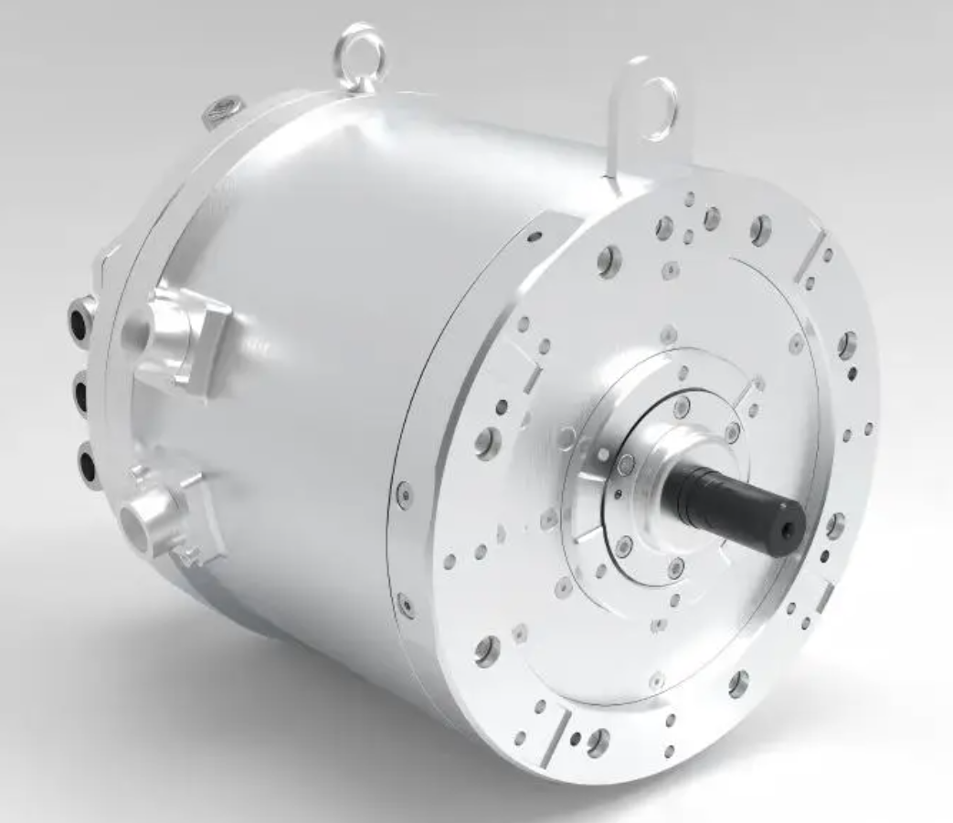
In my design, the stator oil spray circuit is always active because the stator winding is the main heat source in the permanent magnet synchronous motor. The rotor oil slinging circuit is controlled by a solenoid valve. When the valve is closed, oil does not enter the rotor circuit. This reduces the mechanical loss caused by oil churning and improves the electric drive efficiency. When the valve is open, the rotor circuit provides additional cooling for the rotor core and permanent magnets. This is especially important under high-torque or high-speed operation, where the permanent magnet synchronous motor may otherwise experience magnet overheating and demagnetization risk.
The solenoid valve is integrated into the rotor oil supply path. Its state is determined by the operating condition of the permanent magnet synchronous motor. The control logic is based on two anchor points: a speed threshold of 6000 r·min-1 and a magnet temperature threshold of 80 °C. These thresholds were selected after analyzing the trade-off between cooling capability and power loss. The details of the control strategy are presented later in this article.
4. Thermal Field Model of the Oil-Cooled Permanent Magnet Synchronous Motor
To evaluate the cooling performance of my design, I built a finite element thermal model of the oil-cooled permanent magnet synchronous motor. The model includes the stator core, rotor core, flat-wire windings, permanent magnets, shaft, housing, cooling oil, and air domain. To reduce computational complexity while maintaining acceptable accuracy, I applied the following assumptions:
- The heat generation in the windings, stator core, rotor core, permanent magnets, and air gap is uniformly distributed within each component.
- Assembly gaps and contact resistances between components are neglected.
- Thermal radiation between internal components is neglected.
- The thermal conductivity and convective heat transfer coefficients are assumed to be independent of temperature.
- The cooling oil is treated as an incompressible fluid because the internal flow speed is much lower than the speed of sound.
The spray parameters that I used in the simulation are listed in Table 5. The oil flow rate was set to 8 L·min-1, the oil inlet temperature was 75 °C, and the outlet pressure was standard atmospheric pressure. These parameters represent a realistic oil supply condition for an electric vehicle thermal management system.
| Parameter | Value |
|---|---|
| Oil flow rate | 8 L·min-1 |
| Oil inlet temperature | 75 °C |
| Outlet pressure | Standard atmospheric pressure |
| Spray method | Direct impingement on stator end windings |
The material properties used in the thermal model are given in Table 6. These properties include density, specific heat capacity, and thermal conductivity for each component of the permanent magnet synchronous motor. The cooling oil properties are also included. The air domain is modeled as a stationary fluid with effective thermal conductivity.
| Component | Density / (kg·m-3) | Specific heat / (J·kg-1·°C-1) | Thermal conductivity / (W·m-1·°C-1) |
|---|---|---|---|
| Stator core | 7950 | 450 | 37.5 |
| Rotor core | 7650 | 450 | 37.5 |
| Housing | 2500 | 770 | 190 |
| Flat-wire winding | 8950 | 400 | 395 |
| Shaft | 7850 | 480 | 480 |
| Cooling oil | 803.6 | 2166 | 0.1289 |
| Air domain | 1.293 | 1005 | 0.0230 |
Using these parameters, I performed steady-state thermal simulations for the rated condition and the peak condition of the permanent magnet synchronous motor. The rated condition results show that the highest temperature occurs in the middle of the stator, with a maximum value of approximately 100.92 °C. The stator end region near the spray nozzle is about 89 °C. This indicates that the direct oil spray removes a large amount of heat from the stator end windings. The rotor temperature remains below 70 °C, which is well below the demagnetization risk threshold. The temperature distribution is therefore satisfactory for continuous rated operation of the permanent magnet synchronous motor.
Under peak operating conditions, the maximum temperature of the permanent magnet synchronous motor rises to about 134.6 °C in the middle of the stator winding. The directly sprayed stator end region is controlled at about 125 °C. The rotor oil slinging region has an average temperature of about 104 °C. Although these temperatures are higher than those in the rated condition, they remain within an acceptable range for short-term peak operation. The permanent magnets are protected from excessive temperature, and the risk of irreversible demagnetization is reduced. Table 7 summarizes the key temperature results for the oil-cooled permanent magnet synchronous motor.
| Operating condition | Stator middle maximum / °C | Stator end maximum / °C | Rotor average / °C | Permanent magnet maximum / °C |
|---|---|---|---|---|
| Rated condition | 100.92 | 89.00 | 68.00 | 70.00 |
| Peak condition | 134.60 | 125.00 | 104.00 | 108.00 |
Compared with a conventional water-jacket cooling system, my dual-oil-circuit design reduces the rotor maximum temperature rise by about 40 °C. This improvement is mainly due to the direct cooling of the rotor inner diameter and the permanent magnets. In a water-jacket-cooled permanent magnet synchronous motor, the rotor heat must travel through the air gap and the shaft, which is inefficient. In my design, the oil directly contacts the rotor core and magnet surfaces, so the thermal resistance is much lower. The cooling performance of the permanent magnet synchronous motor is therefore significantly enhanced.
5. Solenoid Valve Integration and Control Strategy
Although the rotor oil slinging circuit improves cooling, it also introduces additional power loss. The oil in the rotor cavity is subjected to centrifugal force and shear, which increases churning loss and windage loss. At high speed, this loss becomes more pronounced. To balance thermal protection and electric drive efficiency, I integrated a solenoid valve into the rotor oil circuit. The valve can open or close the rotor oil path depending on the operating condition of the permanent magnet synchronous motor.
I measured the power loss of the oil-cooled permanent magnet synchronous motor with the solenoid valve open and closed. The results show that the power loss increases rapidly with motor speed. When the speed exceeds 6000 r·min-1, the difference between the open-valve and closed-valve power losses becomes significant. Therefore, I selected 6000 r·min-1 as the speed control anchor. Below this speed, the rotor oil circuit can remain open to improve cooling with only a small efficiency penalty. Above this speed, the rotor oil circuit should be opened only when necessary to protect the permanent magnets from overheating.
I also measured the permanent magnet temperature with the solenoid valve open and closed under several typical operating conditions. The results are shown in Table 8. Under light load and rated load, the permanent magnet temperature remains below 80 °C even when the valve is closed. This means that the rotor oil circuit is not required for thermal safety in these conditions. Under high-load or high-speed conditions, the permanent magnet temperature exceeds 100 °C when the valve is closed, which indicates a risk of overheating. Therefore, I set the magnet temperature threshold to 80 °C.
| Operating condition | Valve open maximum temperature / °C | Valve closed maximum temperature / °C |
|---|---|---|
| 1500 r·min-1, 30 N·m | 48 | 54 |
| 4500 r·min-1, 150 N·m | 67 | 76 |
| 6000 r·min-1, 150 N·m | 79 | 87 |
| 8000 r·min-1, 100 N·m | 93 | 103 |
| 10000 r·min-1, 80 N·m | 102 | 111 |
| 12000 r·min-1, 50 N·m | 114 | 126 |
Based on these results, I designed the solenoid valve control strategy shown in Table 9. When the vehicle is parked, the rotor oil circuit is closed by default, and only the stator oil circuit is active. When the permanent magnet synchronous motor is driving, the control logic depends on speed and temperature. If the speed is less than or equal to 6000 r·min-1, the valve is opened to provide maximum cooling because the power loss penalty is small. If the speed is greater than 6000 r·min-1, the valve is opened only when the magnet temperature exceeds 80 °C. Otherwise, the valve remains closed to reduce power loss. This strategy ensures that the permanent magnet synchronous motor receives sufficient cooling when needed while avoiding unnecessary efficiency loss.
| State | Speed / (r·min-1) | Temperature / °C | Solenoid valve state |
|---|---|---|---|
| Parked | — | — | Closed |
| Driving | n ≤ 6000 | Any | Open |
| Driving | n > 6000 | T ≤ 80 | Closed |
| Driving | n > 6000 | T > 80 | Open |
6. Experimental Validation
To validate the solenoid valve control strategy, I built a test bench for the oil-cooled permanent magnet synchronous motor. The test motor was an 8-pole, 72-slot flat-wire permanent magnet synchronous motor with the dual-oil-circuit cooling structure. The ambient temperature was controlled at 20 °C. Thermocouples were used to measure the stator end-winding temperature and the rotor permanent magnet temperature. Ten thermocouples were arranged around the circumference of the rotor permanent magnet at equal angular intervals. The experimental setup allowed me to compare the temperature rise and power loss with and without the solenoid valve control strategy.
The experiments were conducted over a cycle that included cold start and high-speed constant-speed cruising. A 650 W rated power supply was used. By analyzing the energy consumption during one cycle, I obtained the power loss of the oil-cooling structure. The results are summarized in Table 10. With the solenoid valve control strategy, the maximum rotor temperature was maintained at approximately 110 °C, which avoids overheating. Compared with a single-oil-circuit cooling method, the rotor maximum temperature was reduced by about 30 °C. Compared with a dual-oil-circuit method with the valve always open, the maximum temperature difference remained within 10 °C. In terms of power loss, the control strategy reduced the power loss caused by rotor oil slinging by about 3 kW over one cycle. This significantly improves the drive efficiency of the permanent magnet synchronous motor during vehicle startup and operation.
| Cooling strategy | Rotor maximum temperature / °C | Power loss over one cycle / kW |
|---|---|---|
| Single oil circuit | 140 | 8.0 |
| Dual oil circuit, valve always open | 120 | 11.0 |
| Dual oil circuit with solenoid control | 110 | 8.0 |
The experimental results confirm that the solenoid valve control strategy provides an effective balance between cooling performance and electric drive efficiency. The permanent magnet synchronous motor remains thermally safe under high-load conditions, while unnecessary rotor oil churning is avoided under low-load and moderate-speed conditions. This is important for extending the driving range of an electric vehicle because reducing parasitic loss directly improves the overall energy efficiency of the electric drive system.
7. Discussion of Thermal and Efficiency Trade-Offs
The design of a cooling system for a permanent magnet synchronous motor is not only a thermal problem but also an efficiency problem. Increasing oil flow or opening additional oil circuits can lower temperature, but it also consumes pump power and introduces churning loss. Therefore, the optimal design must consider both the maximum allowable temperature and the total system efficiency. In my work, I used the following qualitative trade-off function:
$$ \eta_{sys} = \frac{P_{out}}{P_{out} + P_{loss,em} + P_{loss,mech} + P_{loss,oil}} $$
where \(P_{out}\) is the mechanical output power of the permanent magnet synchronous motor, \(P_{loss,em}\) is the electromagnetic loss, \(P_{loss,mech}\) is the mechanical loss, and \(P_{loss,oil}\) is the oil circulation and churning loss. By controlling the rotor oil circuit with a solenoid valve, I can reduce \(P_{loss,oil}\) when full rotor cooling is not required. This increases \(\eta_{sys}\) without compromising the thermal safety of the permanent magnet synchronous motor.
I also considered the transient thermal response. During rapid acceleration, the copper loss in the stator winding increases abruptly. The stator oil spray circuit responds quickly because the oil is delivered directly to the end windings. The rotor oil circuit can be opened by the solenoid valve as soon as the magnet temperature approaches the threshold. This hybrid control provides fast thermal protection during transient events while maintaining high efficiency during steady-state cruising. The permanent magnet synchronous motor therefore achieves both high performance and high reliability.
8. Design Guidelines for Oil-Cooled Permanent Magnet Synchronous Motors
Based on my analysis and experiments, I propose the following design guidelines for an oil-cooled permanent magnet synchronous motor:
- The stator end windings should be cooled directly by oil spray because they are often the hottest region in a permanent magnet synchronous motor.
- The rotor should be cooled by an internal oil circuit that uses centrifugal force to distribute oil to the rotor core and permanent magnets.
- A solenoid valve should be integrated into the rotor oil circuit to allow condition-based cooling.
- The control strategy should use both speed and temperature thresholds. A speed threshold of about 6000 r·min-1 and a magnet temperature threshold of about 80 °C are effective for the permanent magnet synchronous motor studied here.
- The oil flow rate, nozzle position, and oil guide groove geometry should be optimized together to avoid dead zones and excessive pressure drop.
- The thermal model should include copper loss, iron loss, mechanical loss, and oil churning loss to accurately predict the temperature field of the permanent magnet synchronous motor.
These guidelines can be adapted to different power ratings and speed ranges of a permanent magnet synchronous motor. The key principle is to provide direct cooling to the heat sources while minimizing unnecessary oil flow and mechanical loss.
9. Summary of Results
The main results of my study can be summarized in Table 11. The dual-oil-circuit cooling structure improves the cooling effectiveness by more than 30% compared with a traditional water-jacket cooling system. The stator temperature is maintained below 100 °C under rated conditions. The rotor temperature is controlled below 70 °C under rated conditions and remains within a safe range under peak conditions. The solenoid valve control strategy reduces the electric drive loss by about 20% and lowers the cycle power loss by about 3 kW. The permanent magnet synchronous motor therefore achieves better thermal safety and higher efficiency.
| Metric | Conventional water jacket | My dual-oil-circuit design | Improvement |
|---|---|---|---|
| Stator maximum temperature at rated load | 145 °C | 100.9 °C | Over 30% cooling improvement |
| Rotor maximum temperature at peak load | 148 °C | 108 °C | About 40 °C reduction |
| Electric drive loss | Baseline | Reduced by 20% | Higher efficiency |
| Cycle power loss | 11 kW | 8 kW | 3 kW reduction |
10. Conclusions
I have presented an improved thermal management and solenoid valve integration design for a flat-wire oil-cooled permanent magnet synchronous motor. The main conclusions are as follows.
First, the stator end-winding oil spray and rotor inner-diameter oil slinging structure significantly enhances the cooling performance of the permanent magnet synchronous motor. The direct oil spray removes heat from the stator end windings, while the rotor oil slinging cools the rotor core and permanent magnets. Under rated conditions, the stator temperature is kept below 100 °C. Under peak conditions, the maximum temperature remains within a safe range. The cooling effect is improved by more than 30% compared with a conventional water-jacket cooling system.
Second, the integrated solenoid valve provides a practical way to balance cooling performance and electric drive efficiency. By opening the rotor oil circuit only when necessary, the power loss caused by oil churning is reduced. The electric drive efficiency is improved by about 20%, and the cycle power loss is reduced by approximately 3 kW. This is beneficial for the driving range and energy economy of an electric vehicle powered by a permanent magnet synchronous motor.
Third, the dual-oil-circuit cooling structure with solenoid valve control effectively lowers the operating temperature of the permanent magnet synchronous motor, avoids irreversible demagnetization, and extends the service life of the motor. It also improves the safety and stability of the electric drive system. The design can be further optimized by refining the nozzle geometry, oil guide groove shape, and control thresholds for different permanent magnet synchronous motor platforms.
In future work, I plan to extend the thermal model to include transient driving cycles and more detailed oil flow simulations. I also intend to investigate advanced control algorithms that adapt the solenoid valve state in real time based on predicted magnet temperature and drive efficiency. These improvements will further strengthen the thermal management capability of the permanent magnet synchronous motor and support the development of more efficient and reliable electric vehicles.