
I approach the current-ripple problem in high-power electric vehicle charging from the perspective of phase-count selection. In an electric vehicle charging station, the rear-stage DC converter must deliver tens of kilowatts while keeping switching current stress, capacitor heating, and electromagnetic interference under control. A parallel interleaved Buck converter is an attractive solution because it divides the load current among several phases and raises the effective ripple frequency. However, the total inductor current ripple is not reduced by a simple factor of the phase count under every operating condition. I show that the exact ripple depends on the duty cycle, the instantaneous number of rising and falling phases, and the selected parallel phase count. I then derive a compact ripple coefficient that makes the optimal phase count easy to identify over the full duty-cycle range. The result is a practical method for electric vehicle charging converters that can switch the active phase count as the output voltage and duty cycle change.
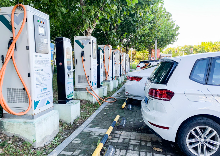
Why Current Ripple Matters in Electric Vehicle Charging
In electric vehicle charging, the DC output stage is expected to provide a controlled voltage or current to the battery pack while maintaining high efficiency. The output current ripple influences battery heating, current-sensor noise, DC-link capacitor RMS current, and the current stress of switching devices. A poorly selected phase count can produce a large total ripple at some duty cycles even when many phases are connected in parallel. Therefore, I treat the phase count as a design variable rather than a fixed number. This is especially important for electric vehicle charging because the output voltage varies widely during constant-current and constant-voltage charging. The duty cycle of a Buck-type rear stage changes accordingly, so the phase count that minimizes ripple at one operating point may be far from optimal at another operating point.
I summarize the main consequences of current ripple and the corresponding design responses in the following table.
| Ripple impact | Physical consequence | Design response in electric vehicle charging |
|---|---|---|
| Device current stress | Higher peak and RMS current in switches and diodes | Select phase count and inductance to reduce total ripple |
| Capacitor heating | Increased output capacitor RMS current and thermal aging | Interleave phases and optimize duty-cycle intervals |
| Battery current quality | Additional battery heating and current-measurement noise | Reduce total inductor current ripple at the charging terminals |
| Electromagnetic interference | Stronger harmonic content around switching and sidebands | Raise effective ripple frequency by phase interleaving |
| Efficiency | Higher conduction and switching losses at unfavorable points | Use adaptive phase selection with hysteresis |
| Control stability | Ripple can disturb current loops and protection thresholds | Use ripple-aware filter design and phase-shedding logic |
The key point for electric vehicle charging is that interleaving improves ripple quality, but the improvement is not monotonic with phase count. I therefore derive the ripple expression first, then use it to select the active phase count.
Interleaved Parallel Buck Topology
I consider a parallel Buck converter with n phases. Each phase has an inductor L, a controlled switch, and a freewheeling diode. The input voltage is ui, the output voltage is uo, and the output filter capacitor is C. The load is represented by a resistor R. The phase currents are iL1 to iLn, and the total inductor current is iLs. The switching period is T, and the duty cycle of every phase is D. The drive signals are shifted by T/n from one phase to the next. This structure is widely used in high-power electric vehicle charging because it allows the use of lower-current devices and reduces the per-phase thermal burden.
| Symbol | Meaning | Role in the analysis |
|---|---|---|
| n | Parallel phase count | Main optimization variable |
| D | Duty cycle | Determines rising and falling phase counts |
| T | Switching period | Sets ripple frequency and slope interval |
| L | Per-phase inductance | Scales the current slope |
| ui, uo | Input and output voltages | Define the Buck voltage conversion ratio |
| iLj | Current of phase j | Individual phase ripple and sharing |
| iLs | Total inductor current | Ripple seen by the output capacitor |
| nu, nd | Rising and falling phase counts | Exact ripple derivation |
| k | Ripple coefficient | Dimensionless optimization metric |
For an ideal parallel Buck converter, the output capacitor current is the sum of the phase currents minus the load current. I write the capacitor current balance as
$$C\frac{du_o}{dt}=i_{L1}+i_{L2}+\cdots+i_{Ln}-\frac{u_o}{R}=i_{Ls}-\frac{u_o}{R}.$$
The average inductor voltage over one switching period gives the steady-state relation
$$L\frac{di_L}{dt}=D u_i-u_o.$$
In steady state, the average inductor voltage is zero, so the ideal voltage gain is
$$D=\frac{u_o}{u_i}.$$
The rising and falling slopes of each phase current are
$$A_u=\frac{u_i-u_o}{L},\qquad A_d=\frac{u_o}{L}.$$
Using the switching function sj for phase j, the phase current can be written as
$$i_{Lj}(t)=I_L+\frac{1}{L}\int\left(u_i s_j(\tau)-u_o\right)d\tau,$$
where IL is the average phase current. The total current is
$$i_{Ls}(t)=\sum_{j=1}^{n}i_{Lj}(t).$$
The phase shift between adjacent drive signals is
$$\Delta t=\frac{T}{n}.$$
Because the phases are interleaved, the total current ripple has a higher fundamental frequency than each phase current. This is beneficial for electric vehicle charging because the output capacitor sees a smaller low-frequency ripple component. However, the exact cancellation depends on how many phases are rising and how many are falling at a given instant. I therefore introduce the rising phase count nu and the falling phase count nd.
Exact Total Current Ripple
For a given duty cycle D and phase count n, the number of phases whose currents are rising at a given interval is
$$n_u=\left\lfloor Dn\right\rfloor+1,$$
and the number of phases whose currents are falling is
$$n_d=\left\lceil (1-D)n\right\rceil-1.$$
These two counts satisfy
$$n_u+n_d=n.$$
This relation is important because it shows that the ripple cancellation is a piecewise function of duty cycle. When Dn is close to an integer, the number of rising phases changes, and the slope of the total current changes abruptly. I use these counts to derive the peak-to-peak total current ripple as
$$\Delta i_{Ls}=\frac{T u_i}{L}\frac{\left[(1-D)n_u-D n_d\right]\left(Dn-n_u+1\right)}{n}.$$
To separate the circuit scaling from the duty-cycle and phase-count effect, I define the ripple coefficient
$$k=\frac{\left[(1-D)\left(\left\lfloor Dn\right\rfloor+1\right)-D\left(\left\lceil (1-D)n\right\rceil-1\right)\right]\left[1+Dn-\left(\left\lfloor Dn\right\rfloor+1\right)\right]}{n}.$$
The total current ripple can then be written compactly as
$$\Delta i_{Ls}=\frac{T u_i}{L}k.$$
This expression is the core of my optimization. For a fixed switching period, input voltage, and inductance, minimizing the total ripple is equivalent to minimizing k over the allowed phase counts. The coefficient k is dimensionless, so it can be tabulated and used in an electric vehicle charging controller without repeated online derivation.
| Quantity | Expression | Interpretation |
|---|---|---|
| Rising phase count | nu = floor(Dn) + 1 | Number of phases with positive current slope |
| Falling phase count | nd = ceil((1 − D)n) − 1 | Number of phases with negative current slope |
| Ripple scale | T ui / L | Circuit-dependent ripple scale |
| Ripple coefficient | k(D, n) | Dimensionless ripple metric for phase selection |
| Optimized phase count | n* = arg min k(D, n) | Phase count that minimizes total ripple |
I note that the ripple coefficient is not monotonic in n. Adding phases generally reduces per-phase current and can improve ripple cancellation, but at certain duty cycles a different phase count gives a better cancellation pattern. This is why a fixed phase count is not optimal for all electric vehicle charging operating points. A practical controller can use a look-up table derived from the expression above.
Optimal Phase Count over the Duty-Cycle Range
I evaluate k for candidate phase counts from two to six over the full duty-cycle range. The lower envelope of the ripple coefficient gives the best phase count at each duty cycle. For a five-phase-capable electric vehicle charging converter, the duty-cycle intervals and the corresponding optimal phase counts are summarized in the following table. The intervals are not evenly spaced because the floor and ceiling functions change at rational values of D.
| Duty-cycle interval | Recommended phase count | Reason for the selection |
|---|---|---|
| 0 to 0.225 | 5 | High phase count improves cancellation at low duty cycle |
| 0.225 to 0.293 | 4 | Four-phase pattern gives lower ripple coefficient |
| 0.293 to 0.365 | 3 | Three-phase cancellation is favorable in this interval |
| 0.365 to 0.452 | 5 | Five-phase interleaving reduces the total ripple |
| 0.452 to 0.548 | 4 | Four-phase pattern is the lower envelope |
| 0.548 to 0.635 | 5 | Five-phase operation minimizes the ripple coefficient |
| 0.635 to 0.708 | 3 | Three-phase operation is preferred |
| 0.708 to 0.775 | 4 | Four-phase operation gives the lowest ripple |
| 0.775 to 1 | 5 | Five-phase operation is optimal near high duty cycle |
I use this table as a design aid for electric vehicle charging. The duty cycle is obtained from the measured input and output voltages, or from the output voltage command. The controller then selects the phase count that minimizes the ripple coefficient. In practice, I add hysteresis at each boundary to avoid frequent phase shedding and reconnection. The hysteresis band can be chosen from the ripple sensitivity and the switching transient tolerance.
| Candidate phase count | Best duty-cycle region | Main advantage | Main penalty |
|---|---|---|---|
| 2 | Limited subrange | Low cost and simple gate drive | Higher per-phase current stress |
| 3 | Middle duty-cycle intervals | Good ripple cancellation with moderate complexity | Not optimal at very low or high duty cycle |
| 4 | Several intermediate intervals | Balanced ripple and thermal distribution | More gate drivers and current sensors |
| 5 | Low and high duty-cycle intervals | Strong ripple cancellation and lower per-phase stress | Higher cost and circulating current risk |
| 6 | Wide range but not always best | Very fine current sharing | Diminishing returns and control complexity |
For electric vehicle charging, the phase count should also respect the current rating of the battery and the thermal limits of the power modules. If the vehicle requests a low charging current, some phases can be shed to reduce switching losses. If the vehicle requests a high charging current, more phases can be activated to reduce per-phase current stress. The ripple-optimal phase count and the loss-optimal phase count are not always identical, so I treat the ripple table as one input to a larger energy-management strategy.
Simulation Model and Parameter Set
I validated the ripple optimization with a simulation model of a multi-phase Buck converter. The model uses ideal switches and diodes with small inductor resistance to represent conduction loss. The control is open loop, with the same duty cycle for all active phases and a phase shift of T/n between adjacent gate signals. This open-loop arrangement isolates the ripple behavior from current-loop dynamics, which is useful for verifying the analytical expression.
| Parameter | Value | Comment |
|---|---|---|
| Switching period T | 0.0001 s | Corresponds to 10 kHz |
| Per-phase inductance L | 100 µH | Equal for all phases |
| Output capacitance C | 100 µF | Output filter capacitor |
| Input voltage ui | 30 V | Low-voltage test condition |
| Inductor resistance rL | 0.01 Ω | Small parasitic resistance |
| Load resistance R | 1 Ω | Resistive load for verification |
| Phase count n | 3, 4, 5 | Candidate active phase counts |
| Duty cycle D | 0 to 1 | Swept for ripple comparison |
I selected two representative duty cycles for detailed comparison: D = 0.33 and D = 0.75. The first represents a low output voltage condition, and the second represents a high output voltage condition. Both are relevant to electric vehicle charging because the battery voltage changes substantially during a charging session.
Simulation Results
At D = 0.33, the three-phase configuration gives the smallest total inductor current ripple. The simulated peak-to-peak ripple is approximately 0.3 A for n = 3, 1.0 A for n = 4, and 1.22 A for n = 5. Compared with the four-phase and five-phase cases, the three-phase case reduces the ripple by about 0.7 A and 0.92 A, respectively. This result agrees with the lower envelope of the ripple coefficient in the corresponding duty-cycle interval.
At D = 0.75, the four-phase configuration gives the smallest ripple. The simulated peak-to-peak ripple is approximately 2.0 A for n = 3, 0 A for n = 4, and 1.1 A for n = 5. The four-phase case achieves an ideal zero-ripple condition in the simulated waveform because the rising and falling phase currents cancel at that duty cycle. Compared with the three-phase and five-phase cases, the four-phase case reduces the ripple by about 2.0 A and 1.1 A, respectively. This confirms that the optimal phase count changes with duty cycle and that the ripple coefficient table is a reliable selection tool for electric vehicle charging.
| Duty cycle | Phase count | Simulated total ripple | Relative comparison |
|---|---|---|---|
| 0.33 | 3 | 0.30 A | Minimum among the tested cases |
| 0.33 | 4 | 1.00 A | 0.70 A higher than n = 3 |
| 0.33 | 5 | 1.22 A | 0.92 A higher than n = 3 |
| 0.75 | 3 | 2.00 A | 2.00 A higher than n = 4 |
| 0.75 | 4 | 0.00 A | Ideal cancellation in simulation |
| 0.75 | 5 | 1.10 A | 1.10 A higher than n = 4 |
I also compare the analytical ripple coefficient with the simulated ripple. The scale factor T ui / L is 0.03 A in the simulation parameter set. Multiplying this scale by the ripple coefficient gives the predicted ripple. The predicted values track the simulated values closely, with small deviations caused by inductor resistance and finite switching transitions. This level of agreement is sufficient for phase-count selection in electric vehicle charging applications.
| Duty cycle | Phase count | Ripple coefficient k | Predicted ripple | Simulated ripple |
|---|---|---|---|---|
| 0.33 | 3 | Approximately 0.010 | Approximately 0.30 A | 0.30 A |
| 0.33 | 4 | Approximately 0.033 | Approximately 0.99 A | 1.00 A |
| 0.33 | 5 | Approximately 0.041 | Approximately 1.23 A | 1.22 A |
| 0.75 | 3 | Approximately 0.067 | Approximately 2.01 A | 2.00 A |
| 0.75 | 4 | Approximately 0.000 | Approximately 0.00 A | 0.00 A |
| 0.75 | 5 | Approximately 0.037 | Approximately 1.11 A | 1.10 A |
These results confirm the central claim of my method: the minimum ripple is obtained by selecting the phase count according to the duty cycle, not by always using the largest available phase count. For electric vehicle charging, this means that a converter with five or more phases can operate with fewer active phases at some operating points and still achieve better current quality and lower switching loss.
Control Implementation
I implement the phase-count selection as a feedforward look-up table combined with a slow feedback trim. The input voltage and output voltage are measured, and the duty cycle is calculated from the voltage ratio. The phase-count selector then compares the duty cycle with the stored interval boundaries and chooses the phase count that minimizes the ripple coefficient. A hysteresis band prevents chattering at the boundaries. The gate signals for the active phases are interleaved with equal phase spacing. When a phase is added or removed, the current-sharing loop is reset softly to avoid transient current spikes.
| Step | Action | Implementation detail |
|---|---|---|
| 1 | Measure input and output voltages | Use filtered ADC samples synchronized to the switching period |
| 2 | Estimate duty cycle | Compute D from the voltage ratio and the control command |
| 3 | Read ripple-optimal phase count | Use the duty-cycle interval table |
| 4 | Apply hysteresis | Require a small duty-cycle margin before changing phase count |
| 5 | Shed or add phases | Enable or disable gate signals with soft current sharing |
| 6 | Verify current balance | Adjust small duty offsets or use average current sharing |
| 7 | Monitor thermal margin | Override the ripple-optimal count if a module exceeds its limit |
I define the phase-count selection rule as
$$n^*(D)=\arg\min_{n\in N}k(D,n),$$
where the candidate set is
$$N=\{2,3,4,5,6\}.$$
For a practical electric vehicle charging controller, the minimization can be replaced by a precomputed table. The table can be stored in nonvolatile memory and indexed by a quantized duty-cycle value. I recommend a resolution of at least 0.005 in duty cycle near the interval boundaries. A finer resolution reduces the risk of selecting a suboptimal phase count when the operating point is close to a boundary.
| Boundary region | Hysteresis width | Purpose |
|---|---|---|
| Low duty-cycle boundary | 0.010 to 0.020 | Prevent phase chattering at light load |
| Middle duty-cycle boundary | 0.008 to 0.015 | Maintain stable current sharing |
| High duty-cycle boundary | 0.010 to 0.020 | Avoid repeated reconnection near full output |
| Thermal override | Temperature-dependent | Protect devices when the optimal phase count is thermally stressed |
In electric vehicle charging, the output current command can change quickly during the transition from constant-current charging to constant-voltage charging. The phase-count selector should therefore use the voltage command and the measured output voltage together. A sudden load step should not cause an immediate phase-count change unless the converter has enough current-sharing bandwidth. I prefer to delay phase shedding until the current command has remained in the new interval for several switching cycles. This avoids unnecessary transients and keeps the electric vehicle charging process smooth.
Design Equations for Ripple, RMS Current, and Loss
I use the ripple expression to size the output capacitor and the phase inductors. The output capacitor RMS current is approximately the RMS value of the total current ripple. For a triangular ripple, I use
$$I_{C,\mathrm{rms}}\approx \frac{\Delta i_{Ls}}{\sqrt{12}}.$$
The per-phase inductor current RMS value is approximately
$$I_{L,\mathrm{rms}}\approx \sqrt{I_L^2+\frac{\Delta i_L^2}{12}},$$
where the per-phase peak-to-peak ripple is
$$\Delta i_L=\frac{u_i D(1-D)T}{L}.$$
The conduction loss of the active switches is approximately
$$P_{\mathrm{cond}}\approx n I_{L,\mathrm{rms}}^2 R_{\mathrm{ds(on)},\mathrm{eq}},$$
and the switching loss has the general dependence
$$P_{\mathrm{sw}}\propto n f_s u_i I_L t_r,$$
where fs is the switching frequency and tr is the equivalent transition time. These equations show the trade-off in electric vehicle charging. Increasing the phase count reduces IL but increases the number of switching events. The ripple-optimal phase count minimizes current stress, while the loss-optimal phase count may be smaller at light load. I therefore combine the ripple table with a loss model and a thermal model.
| Design quantity | Equation | Use in electric vehicle charging |
|---|---|---|
| Per-phase ripple | uiD(1 − D)T / L | Size the inductor and current sensor range |
| Total ripple | (T ui / L)k | Select the ripple-optimal phase count |
| Capacitor RMS current | ΔiLs / √12 | Select the output capacitor and cooling |
| Phase RMS current | √(IL2 + ΔiL2/12) | Select switch and inductor current ratings |
| Conduction loss | n IL,rms2Rds(on),eq | Estimate efficiency and thermal margin |
| Switching loss | Proportional to n fsuiILtr | Balance phase count against frequency |
Worked Example for a High-Power Electric Vehicle Charging Stage
I consider an illustrative electric vehicle charging stage with a 700 V input, a 200 V to 500 V output, a 20 kHz switching frequency, and a 60 µH per-phase inductance. The available phase count is three to five. The duty cycle varies from about 0.29 to 0.71. Using the ripple coefficient table, the controller selects five phases at the low-duty end, three phases in the 0.29 to 0.37 region, four phases in the 0.45 to 0.55 region, and five phases again near the high-duty end. This example shows that the optimal phase count changes several times during an electric vehicle charging session. A fixed five-phase design would be suboptimal in the middle of the charging profile, while a fixed three-phase design would stress the devices at the high-current low-voltage point.
| Output voltage | Approximate duty cycle | Selected phase count | Expected ripple condition |
|---|---|---|---|
| 200 V | 0.286 | 3 | Low total ripple in the three-phase interval |
| 300 V | 0.429 | 5 | Five-phase cancellation is favorable |
| 400 V | 0.571 | 5 | Five-phase interval near the middle-high range |
| 500 V | 0.714 | 4 | Four-phase interval before the high-duty boundary |
I use this worked example to emphasize that the ripple-optimal phase count is not simply the maximum phase count. In electric vehicle charging, the converter operates over a wide voltage range, so the phase-count schedule should be designed together with the battery voltage profile. This is especially useful for fast charging, where the output voltage rises significantly and the duty cycle moves across several interval boundaries.
Practical Nonidealities and Robustness
In a real electric vehicle charging converter, phase inductances are not perfectly equal, switch on-state resistances differ, and gate delays are not identical. These nonidealities produce current-sharing errors and can reduce the ripple cancellation predicted by the ideal model. I account for them by using current-sharing control and by selecting the phase count with a small ripple margin. The mismatch effect on the total current can be approximated as
$$\Delta i_{Ls,\mathrm{mismatch}}\approx\sum_{j=1}^{n}\frac{u_i D(1-D)T}{2L_j}\cos\left(\theta_j\right),$$
where Lj is the actual phase inductance and θj is the phase shift error. The exact value depends on the mismatch pattern, but the expression shows that inductance tolerance and gate timing both matter. I therefore specify tight inductance tolerance and matched gate-drive paths for electric vehicle charging hardware.
| Nonideality | Effect on ripple | Mitigation |
|---|---|---|
| Inductance mismatch | Unequal phase ripple and incomplete cancellation | Use tightly tolerance inductors and current sharing |
| Gate delay mismatch | Phase shift error and sideband ripple | Calibrate gate timing and use matched drivers |
| Switch resistance difference | Unequal current sharing | Use droop control or average current sharing |
| Dead time | Distortion near zero current | Adaptive dead time and current-polarity detection |
| Capacitor ESR | Higher output voltage ripple | Select low-ESR capacitors and parallel banks |
| Thermal imbalance | Local hot spots and derating | Thermal-aware phase shedding |
I also consider the transient behavior during phase shedding. When a phase is disconnected, its current must be transferred to the remaining phases. If the shedding is too fast, the remaining phases can experience a current overshoot. I use a ramp-down of the phase current command before opening the phase switch. The energy stored in the phase inductor is then released in a controlled manner. For electric vehicle charging, this is important because battery current overshoot can trigger protection and interrupt the charging process.
Comparison with Fixed-Phase Operation
I compare the adaptive phase-count method with fixed-phase operation in the following table. The comparison is qualitative but reflects the design trade-offs I observe in electric vehicle charging applications.
| Metric | Fixed maximum phase count | Adaptive ripple-optimal phase count |
|---|---|---|
| Total current ripple | Low at some duty cycles, higher at others | Minimized over the full duty-cycle range |
| Light-load efficiency | Lower because all phases switch | Improved by shedding unnecessary phases |
| Device current stress | Low per phase but high total switching events | Balanced by selecting the best cancellation pattern |
| Control complexity | Simple | Moderate, requiring a look-up table and hysteresis |
| Capacitor RMS current | Operating-point dependent | Reduced at the selected phase count |
| Electric vehicle charging quality | Acceptable but not optimal | Improved current quality and thermal distribution |
For electric vehicle charging, the adaptive method is most valuable when the converter must operate over a wide output-voltage range. A fixed phase count can be adequate if the charging voltage is narrow, but fast charging and wide battery voltage ranges make the adaptive method more attractive. The controller does not need a complex online optimizer; a precomputed table derived from the ripple coefficient is sufficient.
Design Procedure
I summarize my design procedure for ripple-optimized parallel DC converters in electric vehicle charging as follows.
| Step | Design action | Output |
|---|---|---|
| 1 | Define the input voltage, output voltage range, and maximum current | Duty-cycle range and current rating |
| 2 | Choose the switching frequency and per-phase inductance | Ripple scale T ui / L |
| 3 | List the available phase counts | Candidate set N |
| 4 | Compute k(D, n) for each candidate | Ripple coefficient table |
| 5 | Select the lower envelope over duty cycle | Optimal phase-count intervals |
| 6 | Add hysteresis and thermal override | Practical phase-count schedule |
| 7 | Verify current sharing and transient response | Validated control logic |
| 8 | Check capacitor RMS current and device stress | Thermal and reliability margin |
I also recommend verifying the ripple coefficient table against a switching model before finalizing the electric vehicle charging controller. The analytical expression assumes equal inductances and ideal switching. A detailed simulation or hardware test should confirm the interval boundaries and the hysteresis widths. This verification step is especially important near the boundaries where the optimal phase count changes.
Additional Considerations for Electric Vehicle Charging
Electric vehicle charging systems often include a front-end power-factor-correction rectifier and a rear-stage DC converter. The rear-stage ripple optimization does not eliminate the need for a well-designed front end, but it reduces the burden on the output filter and the battery interface. I treat the parallel DC converter as one part of a coordinated electric vehicle charging architecture. The phase-count selection can be coordinated with the battery current command so that phase shedding occurs during low-current intervals rather than during high-current charging.
I also consider the effect of the output capacitor. The total current ripple is the capacitor current ripple in the ideal case. A smaller total ripple reduces capacitor heating and can extend capacitor life. In electric vehicle charging, capacitor banks are often large and expensive, so reducing the RMS ripple current can lead to a more compact and reliable design. The ripple coefficient method helps quantify this benefit without requiring a full harmonic analysis at every operating point.
| Electric vehicle charging requirement | Ripple optimization contribution |
|---|---|
| Wide output voltage range | Duty-cycle-dependent phase selection |
| High current capability | Parallel phases share the load current |
| Low battery heating | Reduced total current ripple |
| High efficiency at light load | Phase shedding reduces switching events |
| Thermal reliability | Balanced phase currents and thermal-aware override |
| Electromagnetic compatibility | Higher effective ripple frequency and lower ripple amplitude |
I have found that the ripple-optimal phase count is a useful intermediate variable between the electrical design and the control design. It gives the hardware designer a clear target for inductor tolerance and current sharing, and it gives the control designer a simple table for real-time operation. In electric vehicle charging, this separation of concerns is valuable because the converter must satisfy both power-quality and battery-interface requirements.
Limitations and Extensions
The analysis in this work assumes continuous conduction mode and ideal switches. In discontinuous conduction mode, the ripple expression changes because some phase currents may reach zero before the end of the switching period. For electric vehicle charging at light load, discontinuous conduction mode can occur, so I recommend adding a mode-dependent correction or using a conservative ripple margin. The phase-count table can still be used as a starting point, but the final schedule should be verified over the full load range.
Another extension is the inclusion of coupled inductors. Coupled inductors can further reduce ripple, but they change the slope relationships and the phase-cancellation pattern. I would derive a modified ripple coefficient for the coupled case and repeat the lower-envelope selection. For electric vehicle charging, coupled inductors may be attractive when the converter volume must be minimized, but they add design complexity and require careful saturation analysis.
| Extension | Effect on the method | Recommended action |
|---|---|---|
| Discontinuous conduction mode | Ripple expression changes at light load | Use mode-aware correction and margin |
| Coupled inductors | New slope and cancellation relationships | Derive a modified ripple coefficient |
| Variable switching frequency | Ripple scale changes with frequency | Include frequency in the look-up table |
| Battery current limit | Phase count may be constrained by current command | Combine ripple table with current-limit logic |
| Thermal derating | Ripple-optimal count may exceed thermal limit | Apply thermal override and reduce phase current |
I also note that the ripple coefficient is based on the total inductor current, not the output voltage ripple. The output voltage ripple depends on the capacitor impedance and the load. For electric vehicle charging, the battery pack presents a low-impedance load, so the output voltage ripple is usually small. However, the capacitor current ripple remains important for thermal design. I therefore use the total inductor current ripple as the primary optimization metric and check the output voltage ripple separately.
Summary of Key Relationships
I summarize the most important relationships for rapid reference in the following table. These relationships form the analytical basis for the phase-count selection method.
| Relationship | Expression | Use |
|---|---|---|
| Voltage gain | D = uo / ui | Estimate operating duty cycle |
| Rising phase count | nu = floor(Dn) + 1 | Count positive-slope phases |
| Falling phase count | nd = ceil((1 − D)n) − 1 | Count negative-slope phases |
| Total ripple | (T ui / L)k | Predict peak-to-peak ripple |
| Ripple coefficient | k(D, n) | Select the optimal phase count |
| Phase shift | T / n | Set interleaved gate timing |
| Capacitor RMS current | ΔiLs / √12 | Size the output capacitor |
For electric vehicle charging, these relationships can be implemented in a low-cost microcontroller. The duty cycle and phase count are the only real-time variables. The inductance and switching period are fixed by the hardware design, so the ripple scale can be precomputed. The ripple coefficient can be stored as a small table indexed by duty cycle. This makes the method practical for production electric vehicle charging equipment.
Conclusion
I have presented a phase-count optimization method for parallel DC converters in high-power electric vehicle charging. The method starts from an exact derivation of the total inductor current ripple and leads to a dimensionless ripple coefficient that depends on duty cycle and phase count. By evaluating the lower envelope of this coefficient, I obtain duty-cycle intervals in which a specific phase count minimizes the ripple. The simulation results confirm that three phases are best at a duty cycle of 0.33 and four phases are best at a duty cycle of 0.75, with the four-phase case reaching an ideal zero-ripple condition in the tested model. These results support the use of adaptive phase selection in electric vehicle charging systems that must operate over a wide output-voltage range.
I conclude that the ripple-optimal phase count is not always the maximum available phase count. For electric vehicle charging, this insight can reduce current stress, capacitor heating, and switching loss while maintaining high current quality. The method is simple enough for a look-up-table implementation and flexible enough to include hysteresis, thermal override, and current-sharing constraints. I expect the approach to be useful in the design of high-power electric vehicle charging converters where efficiency, reliability, and battery-friendly current quality are all important.