
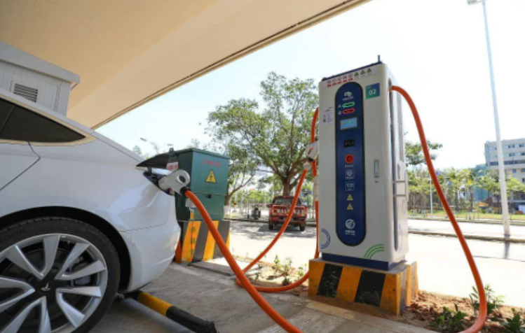
I design high-voltage aluminum electrolytic capacitors for electric vehicle charging power modules, and the work described here began with a very specific safety problem rather than with a routine capacitance or lifetime target. In electric vehicle charging, fast chargers are built from multiple power modules operating in parallel so that output power can be scaled upward while maintaining reasonable module size and thermal density. The high-voltage direct-current bus of each module commonly uses aluminum electrolytic capacitors arranged as two series strings and several parallel branches. This arrangement is efficient and cost-effective, but it creates an overvoltage exposure that is difficult to ignore: when a switching device or a bus capacitor in one module fails short, the healthy capacitor group can be forced to accept nearly the entire bus voltage. The module bridge usually has overvoltage protection, yet the protection delay associated with relay action is approximately 20 ms. That delay is short in human terms but long in capacitor terms. I therefore focused on a capacitor design that could survive 650 V for 20 ms without opening the explosion-proof vent, without internal short circuit, without electrolyte ejection, and without fire.
The application background is electric vehicle charging, but the electrical stress is universal in high-power converters: parallel modules increase available current, series capacitor banks increase voltage capability, and fault coordination determines whether a capacitor sees a controlled overload or an uncontrolled surge. I treated the capacitor as a safety component, not merely as an energy buffer. The design target was a 450 V rated product with 820 µF capacitance in a 30 mm by 60 mm case, capable of withstanding a 650 V transient for 20 ms while keeping the vent closed. The conventional 450 V product family could not meet that target. Its overvoltage endurance was only a few milliseconds to slightly more than ten milliseconds, and in the worst case the electrolyte could ignite after being ejected. I therefore reworked the anode foil, the separator paper, the aluminum shell and vent structure, the electrolyte chemistry, and the aging profile as one coordinated system.
System Context and Design Target
I start the electrical analysis with the normal series voltage-sharing condition because electric vehicle charging modules rarely operate as a single capacitor. In a two-series bank, the ideal voltage across each capacitor is half the bus voltage. In practice, leakage-current mismatch, capacitance tolerance, and thermal gradients cause the split to deviate from the ideal value. For a bank held at a bus voltage for a time interval, the deviation can be expressed as
$$V_{C1}=\frac{V_{bus}}{2}+\frac{\Delta I_{leak}\,t}{2C}$$
$$V_{C2}=\frac{V_{bus}}{2}-\frac{\Delta I_{leak}\,t}{2C}$$
where $$\Delta I_{leak}$$ is the mismatch between the leakage currents of the two series elements, $$t$$ is the time under bias, and $$C$$ is the nominal capacitance. In normal electric vehicle charging operation, the bus voltage is regulated and the mismatch is small. In a short-circuit fault, however, the healthy string no longer shares voltage with a functioning partner. If one side is shorted, the healthy capacitor approaches the full bus voltage:
$$V_{healthy}\approx V_{bus}$$
$$V_{faulted}\approx 0$$
For a 650 V bus and a 450 V rated capacitor, the voltage multiplier is
$$M_V=\frac{650}{450}=1.444$$
That multiplier is not a small margin. It is a deliberate fault-mode stress. I therefore set the design requirement not at the usual ripple or rated-voltage boundary but at the fault boundary itself. The capacitor must hold 650 V for 20 ms with the vent closed. The 20 ms number comes from relay action time, and it is the key coordination parameter between the capacitor and the protection system. If the capacitor opens its vent or degasses before the relay clears the fault, the protection strategy has already failed from a safety perspective.
Table 1 summarizes the operating and safety requirements I used. The table is deliberately written in application language because electric vehicle charging specifications often mix normal operating values, fault values, and test values. The design has to satisfy all three without confusing one for another.
Table 1. Operating and safety requirements for the electric vehicle charging bus capacitor.
| Parameter | Requirement | Design meaning |
|---|---|---|
| Rated voltage | 450 V | Normal continuous bus operation |
| Capacitance | 820 µF | Bus energy buffer for electric vehicle charging module |
| Case size | 30 mm × 60 mm | Fixed mechanical envelope |
| Operating temperature | -40 °C to 105 °C | Outdoor charger enclosure and power-module thermal environment |
| Bank architecture | Two series, multiple parallel | Voltage capability with parallel energy |
| Fault overvoltage | 650 V | Healthy side sees full bus after one side shorts |
| Fault duration | 20 ms | Relay action delay |
| Vent behavior | Must not open | No explosion-proof valve release during the 20 ms event |
| Post-test condition | No internal short, no electrolyte ejection, no fire | Safety acceptance for electric vehicle charging |
I converted these requirements into five design levers: anode foil formation, separator paper structure, shell and vent geometry, electrolyte formulation, and aging profile. Table 2 shows how each lever maps to a specific failure mode. I did not treat any lever as an isolated improvement because the capacitor is a coupled electrochemical, thermal, and mechanical system. A stronger foil without a stable electrolyte can still degas; a high-flash-voltage electrolyte without a pressure-tolerant shell can still open the vent; a stronger shell without a robust separator can still short through a breakdown path.
Table 2. Design levers and the failure modes they address.
| Design lever | Primary function | Failure mode addressed |
|---|---|---|
| HG anode foil formation | Increase withstand strength and stabilize the oxide film | Dielectric breakdown under 650 V transient |
| Long-net plus cylinder-net paper | Increase electrolyte uptake and breakdown voltage | Dry-out, steam pressure, separator puncture |
| Side-rib thick-bottom shell | Raise vent activation pressure and move release point | Early vent opening, bottom bulge, electrolyte spray |
| High-flash-voltage electrolyte | Suppress sparking and repair oxide defects | Flashover, leakage rise, gas generation |
| Graded high-temperature aging | Stabilize oxide and remove weak units | Latent defects, early field failure |
Overvoltage Mechanism and Energy Stress
I model the 20 ms event as a voltage step applied to a capacitor that is already near its normal bus voltage. The exact current depends on the external circuit, cable inductance, module impedance, and the fault path, but the capacitor energy at the end of the step is bounded by the bus voltage and capacitance. For a first-order estimate,
$$E_{ov}\approx \frac{1}{2}C V_{bus}^{2}$$
With $$C=820\,\mu F$$ and $$V_{bus}=650\,V$$, the stored energy is
$$E_{ov}\approx \frac{1}{2}\left(820\times10^{-6}\right)\left(650\right)^{2}\approx 173.2\,J$$
That energy is not all converted to heat in the capacitor, but it indicates the scale of the transient. If the external circuit limits current to 1 A, the capacitor voltage ramp is
$$\frac{dV}{dt}=\frac{I}{C}=\frac{1}{820\times10^{-6}}\approx 1219.5\,V/s$$
The time to reach 650 V from zero at 1 A is therefore
$$t_{650}=\frac{C V}{I}=\frac{\left(820\times10^{-6}\right)\left(650\right)}{1}\approx 0.533\,s$$
In the qualification test I used a 2 s charge interval per cycle, which is much longer than the 20 ms relay delay. I did that intentionally: the 20 ms requirement is the field fault duration, while the 2 s test interval is a severe screening stress that forces the capacitor to hold the overvoltage long enough for weaknesses to reveal themselves. The test is not a claim that the field event lasts 2 s. It is a method to verify that the 20 ms event has margin.
Gas pressure is the second part of the mechanism. During overvoltage, leakage current increases, oxide repair consumes charge, and side reactions can generate gas. A simplified pressure balance is
$$P_g=P_0+\frac{n_g RT}{V_g}$$
where $$P_0$$ is the initial internal pressure, $$n_g$$ is the amount of generated gas, $$R$$ is the gas constant, $$T$$ is temperature, and $$V_g$$ is the free gas volume. Taking the time derivative gives
$$\frac{dP}{dt}=\frac{RT}{V_g}\frac{dn_g}{dt}-\frac{P_g}{V_g}\frac{dV_g}{dt}$$
The first term is gas generation and the second term is volume expansion. A vent opens when the internal pressure reaches the activation pressure:
$$P_g\left(t\right)\ge P_{vent}$$
Therefore, the design strategy is either to reduce $$\frac{dn_g}{dt}$$ or to increase $$P_{vent}$$ while preserving a safe release path. I did both. The electrolyte and paper reduce gas generation, and the shell increases vent activation pressure. That combination is more effective than relying on one side alone.
Anode Foil Formation
The anode foil is the dielectric carrier, so its formation process directly controls overvoltage strength. I selected a special HG formation route rather than the conventional pure boric-acid process. In the HG route, I added two stages of phosphoric-acid treatment within the formation sequence to raise the peak of the formation-voltage curve and to stabilize the resulting oxide film. The conventional foil has low high-frequency equivalent series resistance and low ripple heating, which is attractive for electric vehicle charging because the bus current contains high-frequency ripple. However, the conventional foil can have lower mechanical robustness and a larger leakage-current rebound, which weakens its ability to absorb a sudden overvoltage. The HG foil was selected to keep the low-loss advantage while improving transient withstand.
I express the dielectric thickness and breakdown voltage in the usual form:
$$d_{ox}=\kappa V_{form}$$
$$V_{bd}=E_{bd}d_{ox}$$
where $$d_{ox}$$ is oxide thickness, $$V_{form}$$ is formation voltage, $$\kappa$$ is an anodizing constant, and $$E_{bd}$$ is the breakdown field. The practical point is that a formation process does not merely build thickness; it determines the defect population, crystallinity, and repair behavior of the oxide. In the high-temperature high-voltage test at 115 °C and 450 V for 2000 h, the HG foil showed a more stable oxide structure and a measured withstand increase after 180 s of more than 20 V. That behavior is important for electric vehicle charging because the capacitor may sit at high voltage for long periods and then see a fault transient without warning.
Table 3. Anode foil comparison for the electric vehicle charging bus capacitor.
| Characteristic | Conventional pure boric-acid foil | HG special formation foil |
|---|---|---|
| Formation chemistry | Boric-acid based | Boric acid plus two-stage phosphoric-acid treatment |
| High-frequency ESR | Low | Low, maintained |
| Ripple heating | Low | Low |
| Leakage rebound after high-temperature bias | Relatively large | Reduced |
| Transient overvoltage capability | Limited | Improved |
| 180 s withstand change after 115 °C, 450 V, 2000 h | Baseline | Increase greater than 20 V |
| Application fit | Normal bus operation | Fault-tolerant electric vehicle charging bus |
I also considered the mechanical consequence of foil formation. A foil that is too brittle can crack during winding or expand poorly during thermal cycling. A foil that is too soft can lose compression and increase leakage. The HG route gave me a better balance for the 30 mm by 60 mm case, where the winding density is high and the separator must remain fully impregnated. I therefore fixed the HG foil as the baseline for this electric vehicle charging capacitor rather than using a higher-rated conventional foil, because the latter would have increased size or reduced capacitance within the same case.
Separator Paper Design
The separator paper is often treated as a passive spacer, but in a high-voltage aluminum electrolytic capacitor it is an active safety material. It must hold electrolyte, prevent anode-to-cathode contact, resist puncture, and allow gas transport without drying out. The conventional high-voltage paper is made from wood fiber using a long-net paper machine. Its fiber structure is relatively coarse, its water uptake is low, and its equivalent series resistance is higher. Under high temperature and overvoltage, local heating raises the internal vapor pressure, and the capacitor can bulge and release electrolyte vapor. In electric vehicle charging, where the module may be cycled aggressively, that risk is unacceptable.
I worked with a separator supplier to use a composite long-net plus cylinder-net structure. The long-net layer is made from high-density pure pulp and provides the anti-burr function. The cylinder-net layer uses sisal and Spanish grass pulp to increase electrolyte absorption. The resulting paper has higher purity and approximately one and a half times the water absorption of the conventional paper, which shortens soaking time and improves impregnation. More importantly for this design, the breakdown voltage rises from 400 V to 840 V while the ESR remains low. Table 4 gives the comparison I used for the design review.
Table 4. Separator paper parameters for the electric vehicle charging capacitor.
| Paper structure | Density (g/cm³) | Thickness (µm) | Water absorption (mm/10 min) | ESR (Ω at 1 kHz) | Breakdown voltage (V) |
|---|---|---|---|---|---|
| Conventional long-net | 0.70 | 40 | 4 | 1.5 | 400 |
| Long-net plus cylinder-net | 0.65 | 40 | 30 | 1.4 | 840 |
The water-absorption ratio is
$$R_w=\frac{30}{4}=7.5$$
The breakdown margin relative to the 650 V fault stress is
$$M_{paper}=\frac{840}{650}=1.292$$
I do not interpret that margin as a guarantee by itself, because the paper is impregnated and compressed in the winding. I interpret it as evidence that the separator is no longer the weakest link. The ESR reduction also matters. Ripple heating follows
$$P_{ripple}=I_{rms}^{2}ESR$$
so a lower ESR reduces the temperature rise that drives gas generation. In electric vehicle charging, the bus current is not a clean direct current; it contains switching ripple and load transients. Reducing ESR therefore improves both lifetime and fault tolerance. I specified the composite paper for the full production design, not only for prototypes, because the safety benefit depends on consistent impregnation across the winding.
Shell and Vent Structure
The aluminum shell is the last mechanical barrier before electrolyte ejection. The conventional vent has a Y-shaped pattern with the release point near the center of the bottom. Its activation pressure is typically 1.2 ± 0.2 MPa. That design is adequate for many general-purpose capacitors, but it is not optimal for the electric vehicle charging fault case. A center release point can produce a concentrated bottom bulge, and if the pressure rises quickly the vent may open before the relay clears the fault. I therefore changed the shell to a side-rib thick-bottom design with an activation pressure of 1.7 ± 0.2 MPa. The release point is moved to the side so that even if the bottom deforms, the opening path is less likely to eject electrolyte directly downward or toward adjacent components.
The nominal pressure ratio is
$$\eta_P=\frac{1.7}{1.2}=1.417$$
That is about a 42 percent increase in nominal activation pressure relative to the conventional Y vent. The original design target called for at least a 20 percent increase, and the selected structure exceeds that target. I also apply the vent criterion
$$P_{vent}>P_{peak,20ms}+\Delta P_{margin}$$
where $$P_{peak,20ms}$$ is the peak internal pressure during the 20 ms fault and $$\Delta P_{margin}$$ is a safety margin for unit-to-unit variation. The side-rib design increases the left side of the inequality, while the electrolyte and paper reduce the right side. This is the coordinated approach I used throughout the electric vehicle charging capacitor design.
Table 5. Vent and shell design comparison.
| Feature | Conventional Y vent | Side-rib thick-bottom shell |
|---|---|---|
| Nominal activation pressure | 1.2 ± 0.2 MPa | 1.7 ± 0.2 MPa |
| Release location | Central bottom | Side-oriented release path |
| Bottom bulge behavior | Concentrated central deformation | Distributed side deformation |
| Electrolyte spray risk | Higher | Lower |
| Fault coordination with 20 ms relay delay | Limited | Improved |
| Application fit | General-purpose | Electric vehicle charging bus |
I paid attention to the mechanical stress distribution as well. For a thin-walled pressure vessel, the hoop stress is approximately
$$\sigma_{\theta}=\frac{P r}{t}$$
where $$P$$ is internal pressure, $$r$$ is radius, and $$t$$ is wall thickness. The thick-bottom and side-rib geometry changes the local stiffness and moves the high-stress region away from the central bottom. That does not eliminate stress, but it makes the release behavior more predictable. In practical terms, I wanted the shell to deform before it fragments, and I wanted the release to occur at a controlled side feature rather than at a random weak point. The 1.7 ± 0.2 MPa activation pressure gave that predictability in the electric vehicle charging sample build.
Electrolyte Formulation
The electrolyte is the true cathode of the aluminum electrolytic capacitor, and its chemistry controls flash voltage, leakage current, oxide repair, and gas generation. For this electric vehicle charging application, I needed an electrolyte with high flash voltage, sufficient oxidation capability, good high-temperature stability, and high conductivity. I used ethylene glycol as the main solvent and added mannitol as a co-solvent. I then added an organic carboxylate system with multiple carboxyl functional groups and long branched chains in the 20 to 30 unit range to raise the high-temperature flash voltage. I used a nitro-aromatic hydrogen absorber to capture hydrogen generated during aging and overvoltage, and I added a phosphite to accelerate oxide repair and suppress leakage rebound.
The formulation window I used is given in Table 6. The exact percentages are production windows rather than a single point because electrolyte conductivity and viscosity must be balanced against impregnation and lifetime. The measured electrolyte parameters are given in Table 7. The flash voltage is at least 530 V, the conductivity is 1800 to 2200 µS/cm at 30 °C, the pH is 5.5 to 7.0, and the viscosity is about 60 mPa·s at 30 °C. These values were selected to support the 650 V transient while keeping the 450 V normal operation stable.
Table 6. Electrolyte formulation window.
| Component | Function | Mass fraction (%) |
|---|---|---|
| Ethylene glycol | Main solvent | 70 to 80 |
| Mannitol | Co-solvent and stabilization | 2 to 8 |
| Organic carboxylate additive | Flash-voltage enhancement and oxide repair | 2 to 5 |
| Nitro-aromatic hydrogen absorber | Hydrogen capture and pressure suppression | 0.5 to 2.5 |
| Phosphite additive | Leakage recovery and crack healing | 0.2 to 0.5 |
Table 7. Measured electrolyte parameters.
| Parameter | Value | Design role |
|---|---|---|
| Conductivity at 30 °C | 1800 to 2200 µS/cm | Low ESR and ripple capability |
| Flash voltage | ≥ 530 V | Suppress sparking under overvoltage |
| pH | 5.5 to 7.0 | Oxide stability and corrosion control |
| Viscosity at 30 °C | 60 mPa·s | Impregnation and ion transport balance |
I describe the electrolyte conductivity with the usual ionic relation
$$\sigma=\sum_i z_i \mu_i c_i$$
where $$z_i$$ is charge number, $$\mu_i$$ is ionic mobility, and $$c_i$$ is concentration. Higher conductivity lowers ESR, but it can also increase leakage and gas generation if the solvent system is not stable. I therefore did not maximize conductivity alone. I set a window that supports electric vehicle charging ripple current while keeping the flash voltage above the fault stress. The leakage current itself follows an exponential voltage dependence of the form
$$J_{leak}=J_0\exp\left(\frac{qV}{nkT}\right)$$
so small changes in voltage near the fault level can produce large changes in leakage. The electrolyte must therefore repair the oxide as fast as the leakage damages it. I used the phosphite and carboxylate system to support that repair. A simplified repair rate is
$$\frac{dd_{ox}}{dt}=k_r J_{leak}-k_d e^{-E_a/\left(RT\right)}$$
where $$k_r$$ is the repair coefficient, $$k_d$$ is the dissolution or degradation coefficient, and $$E_a$$ is an activation energy. The exact constants are process-specific, but the design logic is clear: I wanted the first term to dominate during the 20 ms event and the second term to remain small during normal electric vehicle charging operation.
The hydrogen absorber is particularly important for the vent-closed requirement. During aging and overvoltage, hydrogen can be generated at the cathode. If it accumulates, internal pressure rises even when the capacitor is electrically stable. The nitro-aromatic additive captures hydrogen and suppresses that pressure rise. In the overvoltage condition, it can also participate in electrochemical reactions that consume hydrogen. I do not rely on this mechanism alone, but it provides an additional margin that is especially valuable in electric vehicle charging, where the capacitor may experience repeated thermal cycles before the fault event occurs.
Aging and Manufacturing Control
I used a graded high-temperature aging profile rather than a single fixed aging step. The purpose is to stabilize the oxide, drive off weak units, and ensure that the final leakage current is low before shipment. The final aging voltage was referenced to the 500 V product class, which gives more margin than a 450 V-only aging recipe. I also introduced a controlled water-extraction and soaking step in the paper preparation to shorten the soak period and improve impregnation consistency. The hydraulic water extraction was run on a 5 kg batch basis, and the subsequent soak time was reduced accordingly. That detail matters because incomplete impregnation can create local dry spots, and a dry spot is exactly where an overvoltage breakdown can start in an electric vehicle charging bus capacitor.
Table 8. Graded aging and process controls.
| Stage | Purpose | Control variable |
|---|---|---|
| Paper water extraction and soak | Improve impregnation and remove dry spots | Batch water extraction, soak time |
| Low-temperature ramp | Avoid thermal shock to the winding | Ramp rate and hold time |
| First high-temperature aging zone | Stabilize oxide and remove weak units | Temperature and voltage |
| Second high-temperature aging zone | Reduce leakage rebound | Voltage step and duration |
| Final aging reference | Provide overvoltage margin | Reference to 500 V product class |
| Cool-down and electrical screen | Confirm capacitance, ESR, and leakage | Final test limits |
I consider aging a safety process rather than a cosmetic process. A capacitor that passes the 650 V test but has unstable leakage after aging is not acceptable for electric vehicle charging. The graded profile allows me to detect units that would otherwise drift in the field. It also reduces the probability that a weak oxide region survives to the customer. In the production line, the final screen includes capacitance, ESR, leakage current, and visual inspection. The vent is inspected for geometry and activation pressure on a sampling basis.
Qualification Test and Results
I qualified the design on a 450 V, 820 µF, 30 mm by 60 mm sample. The test used a constant-current constant-voltage power supply. I set the voltage directly to 650 V and limited the current to 1 A. The charge time was set to 2 s, and each sample was subjected to five charge-discharge cycles. The acceptance criteria were strict: the explosion-proof vent could remain unopened, but there had to be no internal short circuit, no electrolyte ejection, and no fire. I tested five samples. All five passed. Table 9 gives the test matrix, and Table 10 gives the result summary.
Table 9. Overvoltage qualification test matrix.
| Item | Condition |
|---|---|
| Sample specification | 450 V, 820 µF, 30 mm × 60 mm |
| Sample quantity | 5 |
| Test voltage | 650 V |
| Current limit | 1 A |
| Charge time per cycle | 2 s |
| Number of cycles | 5 |
| Connection | Positive and negative terminals clamped directly |
| Acceptance | Vent may remain closed; no internal short; no electrolyte ejection; no fire |
Table 10. Qualification result summary.
| Test specification | Quantity | Result |
|---|---|---|
| 450 V, 820 µF | 5 | Pass |
The test energy per cycle is approximately
$$E_{cycle}\approx \frac{1}{2}CV^{2}\approx 173.2\,J$$
For five cycles, the accumulated test energy is approximately
$$E_{total}\approx 5E_{cycle}\approx 866\,J$$
I do not use that number as a lifetime rating. I use it to confirm that the sample experienced a meaningful overvoltage stress rather than a shallow pulse. The 2 s charge interval is also much longer than the 20 ms relay delay, so the test is conservative with respect to the field event. The fact that the vent remained closed and no electrolyte was ejected indicates that the coordinated design has margin.
After the electrical test, I inspected the samples for case deformation, vent opening, electrolyte residue, and internal short. I also checked capacitance and ESR to see whether the overvoltage had caused a permanent change. The samples remained electrically functional. That result is important for electric vehicle charging because a capacitor that survives without opening the vent but loses capacitance or develops high leakage is not a satisfactory safety solution. The design target is not merely “no fire”; it is “no fire and no latent failure that compromises the module.”
Discussion of Safety Margins
I summarize the safety logic in Table 11. The table connects each requirement to the design feature and the verification method. This is the form I use when reviewing an electric vehicle charging capacitor because it prevents a common mistake: treating a material improvement as a complete solution. The table makes clear that the 650 V, 20 ms requirement is satisfied by several independent margins, not by a single heroic component.
Table 11. Requirement-to-design-to-verification mapping.
| Requirement | Design feature | Verification |
|---|---|---|
| Withstand 650 V transient | HG anode foil with two-stage phosphoric-acid formation | 180 s withstand test and 650 V overvoltage test |
| Prevent separator breakdown | Long-net plus cylinder-net composite paper | Breakdown voltage 840 V and impregnation inspection |
| Keep vent closed for 20 ms | Side-rib thick-bottom shell at 1.7 ± 0.2 MPa | Pressure test and 650 V cycle test |
| Suppress gas and sparking | High-flash-voltage electrolyte with hydrogen absorber | Flash voltage ≥ 530 V and post-test inspection |
| Reduce latent defects | Graded high-temperature aging with 500 V reference | Leakage, capacitance, and ESR screen |
| Prevent fire | Combined material and mechanical design | No electrolyte ejection, no fire in five-sample test |
I also evaluate the voltage margin and pressure margin explicitly. The voltage stress factor is
$$M_V=\frac{V_{fault}}{V_{rated}}=\frac{650}{450}=1.444$$
The pressure ratio of the new vent to the conventional vent is
$$M_P=\frac{P_{vent,new}}{P_{vent,old}}=\frac{1.7}{1.2}=1.417$$
These two numbers do not multiply into a single safety factor because voltage and pressure are different failure modes. They do show that the design is not relying on a narrow margin in either domain. The electrolyte flash voltage is at least 530 V, and the separator breakdown voltage is 840 V. The weak link is therefore not a single material property but the interaction among leakage current, gas generation, and vent timing. That is why I tested the complete capacitor rather than only the materials.
For electric vehicle charging reliability, I also consider the thermal model. The case temperature rise under ripple current is approximately
$$T_c=T_a+I_{rms}^{2}ESR\,R_{th}$$
where $$T_a$$ is ambient temperature, $$I_{rms}$$ is ripple current, and $$R_{th}$$ is thermal resistance. Lower ESR from the composite paper and the electrolyte helps keep $$T_c$$ low. The lifetime model I use for screening is
$$L=L_0\,2^{\left(T_0-T\right)/10}\left(\frac{V_0}{V}\right)^{n}$$
where $$L_0$$ is the reference life, $$T_0$$ is the reference temperature, $$V_0$$ is the reference voltage, and $$n$$ is a voltage acceleration exponent. This model is not a substitute for the overvoltage test, but it helps me compare design variants. In electric vehicle charging, the capacitor may operate at high ambient temperature and high ripple current, so a design that only passes the overvoltage test but has poor thermal margin is not acceptable. I therefore selected the lower-ESR paper and the high-conductivity electrolyte together, not separately.
The series voltage-sharing mismatch is another practical concern. I estimate the mismatch voltage as
$$\Delta V_{share}=\frac{\Delta I_{leak}\,t_p}{C}$$
where $$t_p$$ is the time under bias. In normal operation, the mismatch is small. In the fault case, the healthy capacitor sees the full bus voltage, so the series mismatch is no longer the dominant issue. The dominant issue becomes the absolute withstand of the healthy capacitor. That is why the 650 V, 20 ms requirement drove the foil and electrolyte design more strongly than the normal voltage-sharing tolerance. I still control leakage mismatch in production because it affects lifetime and because it can create an uneven aging pattern across the bank.
Manufacturing Consistency and Field Relevance
I designed this capacitor for electric vehicle charging, where the field profile includes daily charging cycles, high ambient temperature, humidity, vibration, and occasional grid transients. The overvoltage event is rare, but it is exactly the kind of rare event that determines whether a charger is safe. A conventional 450 V capacitor may work for years under normal ripple and then fail during a single fault because the fault stress is outside its design window. My approach was to bring the fault stress into the design window without increasing the case size. That required the HG foil, the composite paper, the side-rib shell, and the high-flash-voltage electrolyte to work together.
I pay particular attention to consistency in the paper impregnation and the electrolyte fill. If the fill volume is low, the top of the winding can dry out, and the overvoltage strength drops. If the fill volume is too high, the internal pressure can rise faster during heating. The production window is therefore narrow. I use a controlled soak and a graded aging profile to stabilize the fill before final test. In electric vehicle charging modules, the capacitor may be mounted in different orientations, so I also verify that the electrolyte distribution does not create a local dry region. The composite paper helps because its cylinder-net layer holds electrolyte more uniformly than the conventional long-net paper.
I also considered the interaction between the vent and the module enclosure. The side-rib design moves the release path to the side, which is beneficial when the capacitor is mounted near a printed circuit board or a busbar. A central bottom release can direct electrolyte toward sensitive components. The side release is not a substitute for proper module fusing and relay protection, but it reduces the consequence of a vent opening. In electric vehicle charging, the capacitor is part of a safety chain that includes fuses, contactors, gate drivers, and software protection. The capacitor should not be the first element to fail in a way that creates a fire.
I further evaluated the risk of repeated overvoltage events. A single 20 ms event is the qualification target, but field events can occur more than once over the life of a charger. The electrolyte repair capability is therefore important. The phosphite additive and the carboxylate system help heal oxide cracks after a transient. The hydrogen absorber helps prevent pressure accumulation after repeated events. The graded aging process removes units with unstable leakage before shipment. These measures do not make the capacitor infinite-life under overvoltage, but they improve the probability that the capacitor remains safe after more than one event. That is a practical requirement for electric vehicle charging infrastructure, where maintenance access may be limited.
Comparative Design Logic
I summarize the design evolution in Table 12. The table compares a conventional 450 V approach with the coordinated approach I used. The comparison is useful because it shows where the safety gain comes from. It is not a single material change. The anode foil raises the dielectric withstand, the paper raises the separator withstand and lowers ESR, the shell raises the vent pressure, the electrolyte raises the flash voltage and repair rate, and the aging profile reduces latent defects. Each change is modest by itself, but together they move the capacitor from a few milliseconds of overvoltage endurance to a 20 ms fault window with margin.
Table 12. Conventional design versus coordinated electric vehicle charging design.
| Design aspect | Conventional 450 V approach | Coordinated design |
|---|---|---|
| Anode foil | Pure boric-acid formation | HG formation with two-stage phosphoric acid |
| Separator paper | Long-net wood fiber | Long-net plus cylinder-net composite |
| Vent | Central Y pattern, 1.2 ± 0.2 MPa | Side-rib thick bottom, 1.7 ± 0.2 MPa |
| Electrolyte | Standard high-voltage solvent system | High-flash-voltage system with hydrogen absorber and phosphite |
| Aging | Single-stage or lower reference | Graded high-temperature aging with 500 V reference |
| Overvoltage endurance | Few milliseconds to slightly more than ten milliseconds | 650 V, 20 ms target with vent closed |
| Safety outcome | Risk of electrolyte ejection and fire | No vent release, no electrolyte ejection, no fire in qualification |
I do not claim that the design is universal for all electric vehicle charging systems. The correct capacitor depends on bus voltage, module topology, relay timing, fusing, and thermal environment. What I claim is that the design method is transferable. First, define the fault voltage and fault duration. Second, calculate the series and short-circuit voltage distribution. Third, set the vent pressure above the fault pressure with margin. Fourth, select foil, paper, and electrolyte so that the dielectric and separator withstand exceed the fault voltage. Fifth, verify the complete capacitor under a stress that is at least as severe as the field event. I followed that method for this electric vehicle charging bus capacitor.
Conclusion
I developed a high-voltage aluminum electrolytic capacitor for electric vehicle charging bus applications that must survive a 650 V, 20 ms overvoltage without opening the explosion-proof vent. The starting point was a 450 V, 820 µF, 30 mm by 60 mm product used in a two-series multi-parallel bus. The fault mechanism is clear: a shorted switch or bus capacitor can force the healthy capacitor to absorb the full bus voltage, and the relay protection delay is approximately 20 ms. Conventional 450 V capacitors do not have enough overvoltage endurance for that window, and electrolyte ejection can create a fire risk.
I addressed the problem with five coordinated changes. I used an HG anode foil with two-stage phosphoric-acid treatment to strengthen the oxide and improve transient withstand. I used a long-net plus cylinder-net composite separator with higher water absorption and an 840 V breakdown voltage. I used a side-rib thick-bottom shell with a 1.7 ± 0.2 MPa vent activation pressure. I formulated a high-flash-voltage electrolyte with a nitro-aromatic hydrogen absorber and a phosphite repair additive. I used a graded high-temperature aging profile with a 500 V reference. The qualification test used five samples at 650 V, 1 A, 2 s charge time, and five cycles. All five samples passed with no vent release, no internal short, no electrolyte ejection, and no fire.
For electric vehicle charging, the value of this design is not only the test result. It is the safety margin in the fault path. The voltage stress factor is 1.444, the vent pressure ratio is 1.417, the separator breakdown margin is 1.292, and the electrolyte flash voltage is at least 530 V. These margins are not independent guarantees, but together they make the capacitor tolerant of the relay delay instead of dependent on it. I conclude that a coordinated material and mechanical design can meet the 650 V, 20 ms requirement in a case size that is practical for electric vehicle charging power modules. The design is stable, cost-effective, and suitable for production, and it directly addresses the fire risk that motivated the project.
The broader lesson I take from this work is that electric vehicle charging capacitors should be specified by fault behavior, not only by rated voltage and capacitance. A 450 V capacitor is not automatically safe on a 650 V fault simply because the normal bus is 450 V. The series architecture, the relay delay, the vent pressure, the separator breakdown, and the electrolyte chemistry all interact. I therefore specify the capacitor with a fault-mode table, a pressure criterion, a flash-voltage criterion, and a complete overvoltage test. That approach gives the electric vehicle charging module designer a component that supports the safety strategy rather than undermining it.