
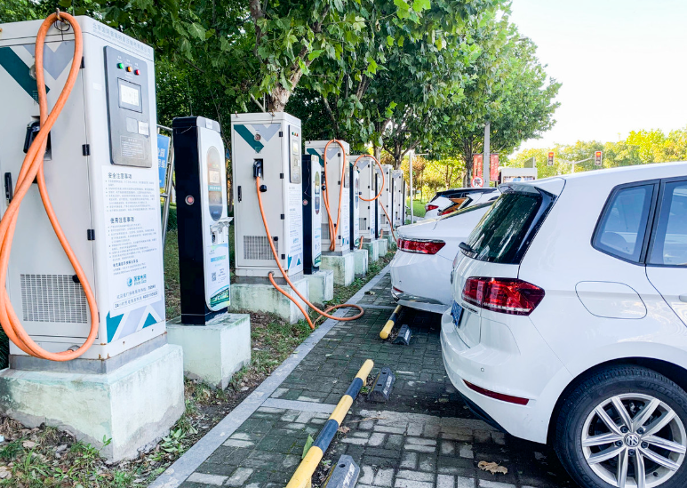
I designed this integrated dual-gun DC charger around a simple but demanding objective: deliver high-power electric vehicle charging in a compact, reliable, and serviceable package that can be deployed at scale. The rapid growth of electric vehicle charging infrastructure has made space, thermal performance, installation cost, and operational uptime decisive factors. Traditional split-type equipment often occupies too much ground area, complicates cable management, and creates thermal and maintenance penalties. I therefore treated the charger as an integrated electromechanical system in which structure, airflow, power electronics, ergonomics, manufacturability, and field service are optimized together. The unit supports two vehicles simultaneously, improves service throughput in constrained sites, and provides a practical pathway for denser electric vehicle charging networks. In my design work, I focused on three measurable dimensions: mechanical strength and seismic stability, environmental protection with efficient heat rejection, and human-centered operation with low maintenance burden.
Design Architecture and Engineering Targets
I established the architecture from the outside inward. The enclosure provides the primary structural frame, the two gun bays establish the user interface, and the internal volume is divided into an electrical compartment and a power-module compartment. This separation is not merely a packaging choice; it is the basis for thermal isolation, electrical safety, and modular assembly. I set the design targets so that the charger can operate in outdoor electric vehicle charging environments, including highway service areas and urban parking structures. The mechanical target requires a wind-load resistance of at least \(0.6\ \mathrm{kN/m^2}\), seismic performance corresponding to intensity 8, an enclosure rating of IP55, and a gun-to-gun operating spacing of at least \(730\ \mathrm{mm}\). The user interface targets a gun operating height of \(1.0\ \mathrm{m}\pm0.1\ \mathrm{m}\) and an insertion or withdrawal force below \(30\ \mathrm{N}\). These values are not arbitrary; they translate directly into user comfort, cable life, and structural reliability.
I used a compact set of governing relationships during concept design. Wind pressure is estimated from the basic velocity pressure:
$$q=\frac{1}{2}\rho v^{2}$$
where \(q\) is the velocity pressure, \(\rho\) is air density, and \(v\) is wind speed. The resulting wind force on the enclosure is:
$$F_{w}=C_{d}A q$$
where \(C_d\) is the drag coefficient and \(A\) is the projected area. I required the design pressure to meet or exceed the specified \(0.6\ \mathrm{kN/m^2}\) threshold after applying the appropriate shape factor. For seismic isolation, I evaluated the frequency ratio between the isolated structure and the dominant excitation:
$$r_{f}=\frac{f_{s}}{f_{p}}>2.0$$
where \(f_s\) is the isolated system frequency and \(f_p\) is the predominant excitation frequency. A frequency ratio above 2.0 indicates effective dynamic decoupling. I also checked the maximum displacement using a response-spectrum approximation:
$$D_{max}=\frac{S_{a}(T)M}{K_{eff}}$$
where \(S_a(T)\) is the spectral acceleration, \(M\) is the effective mass, and \(K_{eff}\) is the effective stiffness of the isolation system. These calculations guided the frame topology, anchor layout, and isolation bearing selection.
| Design dimension | Target or constraint | Engineering rationale | Verification method |
|---|---|---|---|
| Wind resistance | \(\geq 0.6\ \mathrm{kN/m^2}\) | Outdoor electric vehicle charging stability | Structural calculation and pressure check |
| Seismic performance | Intensity 8 | Stable operation in seismic zones | Response-spectrum analysis |
| Enclosure protection | IP55 | Dust and water-jet resistance | Ingress protection test |
| Gun spacing | \(\geq 730\ \mathrm{mm}\) | Prevent cable entanglement | Layout measurement and ergonomic review |
| Operating height | \(1.0\ \mathrm{m}\pm0.1\ \mathrm{m}\) | Comfortable reach for adult users | Anthropometric and field evaluation |
| Operating force | \(\leq 30\ \mathrm{N}\) | Low physical effort during connection | Force gauge test |
| Module temperature | \(\leq 65^\circ\mathrm{C}\) at \(40^\circ\mathrm{C}\) ambient | Protect power electronics and maintain output | Thermal simulation and field monitoring |
| Electrical compartment temperature | \(\leq 55^\circ\mathrm{C}\) at \(40^\circ\mathrm{C}\) ambient | Maintain insulation and component life | Thermal simulation and sensor logging |
Structural Layout and Human-Centered Operation
I arranged the two gun bays symmetrically to create a balanced visual envelope and a predictable operating rhythm. The left and right operating zones remain at least \(730\ \mathrm{mm}\) apart, and the cable guide channels keep the two cables separated when both guns are in use. This is important in electric vehicle charging because cable crossing is not only inconvenient; it can accelerate insulation wear, increase connector strain, and create tripping hazards. I set the gun height at approximately \(1.0\ \mathrm{m}\), which allows most adult users to connect and disconnect without bending or stretching. I also limited the operating force to \(30\ \mathrm{N}\) or less. The perceived effort depends on insertion geometry, latch design, cable stiffness, and the user’s posture. I therefore treated the interface as a biomechanical system rather than a simple mechanical connector.
I used a simplified reach and posture model to check the interface. The horizontal reach requirement can be expressed as:
$$R_{h}=\sqrt{(x_{g}-x_{s})^{2}+(y_{g}-y_{s})^{2}}$$
where \((x_g,y_g)\) is the gun position and \((x_s,y_s)\) is the user’s shoulder reference point. The vertical operating height is constrained by:
$$h_{min}\leq h_{g}\leq h_{max}$$
with \(h_{min}=0.9\ \mathrm{m}\) and \(h_{max}=1.1\ \mathrm{m}\) for the target population. I also expressed the cable bending radius constraint as:
$$R_{b}\geq k_{b}D_{c}$$
where \(R_b\) is the bending radius, \(D_c\) is the cable outer diameter, and \(k_b\) is the manufacturer’s minimum bending factor. The cable guide channels and strain relief features maintain this radius during repeated use. These details matter in high-frequency electric vehicle charging because user behavior is variable and often hurried.
| Layout parameter | Value | Design effect |
|---|---|---|
| Overall width | \(730\ \mathrm{mm}\) | Compact footprint with two operating zones |
| Overall height | \(1450\ \mathrm{mm}\) | Accessible interface and protected internal volume |
| Overall depth | \(450\ \mathrm{mm}\) | Reduced parking-space intrusion |
| Gun-to-gun spacing | \(\geq 730\ \mathrm{mm}\) | Separate cable paths and simultaneous use |
| Gun operating height | \(1.0\ \mathrm{m}\pm0.1\ \mathrm{m}\) | Comfortable reach without bending |
| Maximum operating force | \(30\ \mathrm{N}\) | Low insertion and withdrawal effort |
| Cable management | Dedicated guide channels | Reduced entanglement and connector strain |
| Service access | Front and side modular panels | Fast maintenance in public electric vehicle charging sites |
Materials and Topology Optimization
I selected zinc-coated steel as the primary frame material because it combines adequate tensile strength with good corrosion resistance and reasonable mass. The material has a tensile strength of at least \(200\ \mathrm{MPa}\), and its density is approximately \(2.7\ \mathrm{g/cm^3}\), which is substantially lower than conventional heavy steel sections used in older charger architectures. I specified surface passivation followed by an outdoor coating system to improve corrosion resistance. Salt-spray testing demonstrated that the coated system can exceed \(1000\ \mathrm{h}\) without significant red rust. For a public electric vehicle charging asset, this matters because the unit may be exposed to road salt, humidity, dust, and repeated washing.
I used finite-element analysis and topology optimization to remove non-load-bearing material from the cabinet frame. The optimization problem can be written as:
$$\min_{\rho}\ C(\rho)=\mathbf{u}^{T}\mathbf{K}(\rho)\mathbf{u}$$
subject to:
$$\sum_{e=1}^{N}\rho_{e}V_{e}\leq V_{target}$$
$$0<\rho_{min}\leq \rho_{e}\leq 1$$
where \(\rho_e\) is the relative density of element \(e\), \(\mathbf{u}\) is the displacement vector, \(\mathbf{K}\) is the stiffness matrix, \(V_e\) is the element volume, and \(V_{target}\) is the allowable material volume. I constrained maximum stress and maximum deflection so that the optimized frame would not sacrifice stiffness or safety. The optimized design reduced overall mass by approximately 15% while maintaining structural performance. That reduction lowers transport and installation effort and reduces the foundation load in electric vehicle charging deployments where concrete work is expensive and time-consuming.
| Material property | Design value | Benefit |
|---|---|---|
| Frame material | Zinc-coated steel | Strength with corrosion resistance |
| Tensile strength | \(\geq 200\ \mathrm{MPa}\) | Structural safety margin |
| Density | \(2.7\ \mathrm{g/cm^3}\) | Lower mass than conventional heavy steel |
| Surface treatment | Passivation plus outdoor coating | Improved weather resistance |
| Salt-spray resistance | \(>1000\ \mathrm{h}\) | Suitable for coastal and highway electric vehicle charging |
| Topology optimization | 15% mass reduction | Lower transport and foundation cost |
| Coating thickness | \(\geq 120\ \mu\mathrm{m}\) | UV and corrosion protection |
| Sealing material | EPDM gasket | Elasticity from \(-40^\circ\mathrm{C}\) to \(120^\circ\mathrm{C}\) |
Thermal Management and Dual-Air-Duct Architecture
Thermal design is the central technical challenge in a compact integrated charger. Higher power density reduces footprint, but it also concentrates heat sources. I separated the thermal paths into an independent electrical-compartment duct and a module-compartment cooling zone. The electrical compartment uses a dedicated axial-fan path to discharge heat directly to the exterior and prevent hot air from entering the module area. The module compartment uses an intelligent air-cooling system with large heat sinks and optimized airflow paths. The fan speed is modulated according to module temperature, which reduces acoustic noise and fan energy when the charger is lightly loaded while preserving cooling capacity during high-power electric vehicle charging.
I evaluated the thermal network with a resistance model. The junction-to-ambient thermal resistance can be approximated as:
$$R_{th,ja}=R_{th,jc}+R_{th,cs}+R_{th,sa}$$
where \(R_{th,jc}\) is junction-to-case resistance, \(R_{th,cs}\) is case-to-sink resistance, and \(R_{th,sa}\) is sink-to-ambient resistance. The allowable power dissipation for a given temperature rise is:
$$P_{diss}=\frac{T_{j,max}-T_{a}}{R_{th,ja}}$$
I also used the air-side energy balance:
$$Q_{out}=\dot{m}c_{p}\Delta T$$
where \(\dot{m}\) is mass flow rate, \(c_p\) is specific heat, and \(\Delta T\) is the air temperature rise. For a fixed duct geometry, the fan laws provide useful scaling relationships:
$$\frac{Q_{2}}{Q_{1}}=\frac{N_{2}}{N_{1}}$$
$$\frac{P_{2}}{P_{1}}=\left(\frac{N_{2}}{N_{1}}\right)^{3}$$
where \(Q\) is volumetric flow, \(N\) is fan speed, and \(P\) is fan power. These relationships helped me choose a control range that balances thermal margin against parasitic energy consumption. I also checked duct pressure loss using:
$$\Delta p=f\frac{L}{D}\frac{\rho v^{2}}{2}$$
where \(f\) is the friction factor, \(L\) is duct length, \(D\) is hydraulic diameter, \(\rho\) is air density, and \(v\) is air velocity. The dual-duct arrangement reduces recirculation and prevents the electrical compartment from heating the power modules. In my Flotherm simulations, at \(40^\circ\mathrm{C}\) ambient and full-load dual-gun operation, the maximum module temperature remained below \(65^\circ\mathrm{C}\) and the electrical-compartment temperature remained below \(55^\circ\mathrm{C}\). These values provide margin below the safety thresholds and support stable electric vehicle charging performance.
| Thermal parameter | Simulated or measured value | Threshold | Interpretation |
|---|---|---|---|
| Ambient temperature | \(40^\circ\mathrm{C}\) | Design condition | High-temperature electric vehicle charging scenario |
| Maximum module temperature | \(\leq 65^\circ\mathrm{C}\) | Below safety limit | Adequate thermal margin |
| Electrical compartment temperature | \(\leq 55^\circ\mathrm{C}\) | Below safety limit | Reduced insulation aging risk |
| Field module temperature | \(60^\circ\mathrm{C}\) at \(35^\circ\mathrm{C}\) ambient | \(75^\circ\mathrm{C}\) | Stable continuous operation |
| Field electrical compartment temperature | \(50^\circ\mathrm{C}\) at \(35^\circ\mathrm{C}\) ambient | \(75^\circ\mathrm{C}\) | No hotspot concentration |
| Cooling control | Temperature-modulated fan speed | Adaptive | Lower noise and fan energy at part load |
| Duct configuration | Independent electrical and module paths | No cross-heating | Improved reliability in electric vehicle charging |
Seismic and Mechanical Integrity
I adopted a base-isolation approach for seismic protection. Natural rubber bearings provide horizontal flexibility and recentering capability, and their horizontal stiffness can be selected to shift the isolated frequency away from dominant seismic excitation. The isolation system was verified using response-spectrum analysis. Under intensity-8 excitation, the maximum cabinet displacement remained approximately \(1\ \mathrm{mm}\), and the maximum stress in the concentrated regions remained approximately \(60\ \mathrm{MPa}\), which is well below the material yield strength. This result is important for electric vehicle charging equipment installed near roadways, parking structures, and public buildings where seismic and vibration loads must be considered together.
I also checked the dynamic amplification factor:
$$D_{amp}=\frac{1}{\sqrt{(1-r^{2})^{2}+(2\zeta r)^{2}}}$$
where \(r=\omega/\omega_n\) is the frequency ratio and \(\zeta\) is the damping ratio. For base isolation, the objective is to keep the superstructure response low while providing sufficient displacement capacity. The isolator displacement demand can be approximated as:
$$u_{d}=\frac{S_{a}(T_{iso})T_{iso}^{2}}{4\pi^{2}}$$
where \(T_{iso}\) is the isolated period. I confirmed that the bearing displacement remained within the design gap and that the anchor and frame details could accommodate the seismic drift without contact or local buckling. The combination of topology-optimized frame members, base isolation, and stress-controlled joints gives the charger a mechanically robust envelope for public electric vehicle charging.
| Mechanical check | Result | Acceptance criterion | Conclusion |
|---|---|---|---|
| Maximum seismic displacement | \(\approx 1\ \mathrm{mm}\) | Within bearing gap | Pass |
| Maximum local stress | \(\approx 60\ \mathrm{MPa}\) | Below yield strength | Pass |
| Frequency ratio | \(>2.0\) | Effective isolation | Pass |
| Full-load structural deformation | \(0.15\ \mathrm{mm}\) | \(<0.5\ \mathrm{mm}\) | Pass |
| Deformation recovery | Complete after charging | No permanent set | Pass |
| Vibration test | \(10\) to \(55\ \mathrm{Hz}\), \(0.35\ \mathrm{mm}\), \(2\ \mathrm{h}\) | No loosening or malfunction | Pass |
Manufacturing and Modular Assembly
I divided the charger into three preassembled units: the module compartment, the electrical compartment, and the internal electrical subzones for AC distribution, control, and DC output. Each unit is prewired and tested before final integration. The final assembly then becomes a controlled process of unit docking, torque verification, sealing, and functional test. This modular approach reduced installation time from approximately \(8\ \mathrm{h}\) to \(4\ \mathrm{h}\) in my pilot production and field installation review. Faster installation is valuable in electric vehicle charging because site downtime and construction disruption directly affect service availability and project economics.
I applied differentiated corrosion protection according to exposure and function. Critical connection bolts use zinc-flake coating with good salt-spray performance. Cabinet seals use EPDM gaskets that remain elastic over a wide temperature range. External metal parts receive a two-layer coating system with a zinc-rich primer and an outdoor topcoat. The coating thickness exceeds \(120\ \mu\mathrm{m}\). I also specified torque control and traceable fastening for structural and electrical connections. The assembly sequence can be summarized by the following cumulative time model:
$$T_{assembly}=T_{pre}+T_{dock}+T_{seal}+T_{test}$$
where \(T_{pre}\) is preassembly time, \(T_{dock}\) is unit docking time, \(T_{seal}\) is sealing time, and \(T_{test}\) is functional test time. By moving most wiring and verification into preassembly, I reduced the field portion of \(T_{assembly}\) and improved repeatability. The same logic applies to maintenance: a failed module or component can be isolated and replaced without dismantling the entire charger.
| Manufacturing element | Approach | Measured or expected benefit |
|---|---|---|
| Preassembled module compartment | Factory wiring and test | Improved consistency |
| Electrical compartment | Separate AC, control, and DC zones | Safer assembly and service |
| Final docking | Guided mechanical and electrical interfaces | Reduced field labor |
| Installation time | Reduced from \(8\ \mathrm{h}\) to \(4\ \mathrm{h}\) | Faster electric vehicle charging deployment |
| Critical fasteners | Zinc-flake coating | \(1000\ \mathrm{h}\) salt-spray resistance |
| Sealing | EPDM gasket | Long-term environmental protection |
| External coating | Zinc-rich primer plus outdoor topcoat | UV and corrosion resistance |
| Production efficiency | Modular batch assembly | Approximately 40% improvement |
Engineering Applications in Electric Vehicle Charging
I evaluated the charger in two representative electric vehicle charging environments. The first is a highway service area, where the unit must tolerate humidity, salt spray, temperature variation, and intermittent high-demand periods. The second is an urban underground parking facility, where space is limited and queue management is critical. These two environments stress different aspects of the design. The highway site stresses environmental durability and high-power availability. The underground site stresses compactness, cable management, and service access. The same integrated architecture performed well in both because the thermal, structural, and modular design choices were made together rather than sequentially.
In the highway service-area pilot, the charger operated over a temperature range of \(-20^\circ\mathrm{C}\) to \(+50^\circ\mathrm{C}\) and a relative humidity range of 5% to 90% without condensation. The 160 kW output and dual-gun configuration allowed two vehicles to charge in parallel, reducing the average station dwell time during peak periods. The intelligent air-cooling system maintained stable module temperatures, and the communication interface uploaded charging data for maintenance planning. For electric vehicle charging operators, this data stream is valuable because it supports demand-based scheduling, fault diagnosis, and predictive maintenance.
In the underground parking pilot, I reduced the equipment depth to \(450\ \mathrm{mm}\), kept the width at \(730\ \mathrm{mm}\), and set the height at \(1450\ \mathrm{mm}\). This allowed a one-space-one-charger layout in standard parking bays and reduced space consumption by approximately 30% compared with a conventional split system. The dual-gun design increased service capacity without duplicating the cabinet, cable management, and foundation. In operation, the unit served an average of 15 charging sessions per day, approximately 1.8 times the throughput of nearby single-gun equipment. That result directly addresses queuing at urban electric vehicle charging sites.
| Application scenario | Primary constraint | Design response | Observed or expected outcome |
|---|---|---|---|
| Highway service area | Humidity, salt spray, intermittent peaks | IP55 enclosure, coated frame, dual-gun output | Stable high-power electric vehicle charging |
| Highway service area | Long-distance travel demand | 160 kW output and fast connector access | Reduced dwell time |
| Urban underground parking | Limited space | \(450\ \mathrm{mm}\) depth and integrated cabinet | One-space-one-charger layout |
| Urban underground parking | Charging queues | Dual-gun simultaneous service | Approximately 1.8 times single-gun throughput |
| Public parking | User effort and cable wear | Ergonomic height and cable guides | Improved user experience |
| Operator maintenance | Downtime and service cost | Modular compartment replacement | Faster repair and lower maintenance burden |
Economic Performance and Lifecycle Cost
I assessed economics from the perspective of an electric vehicle charging site owner. The integrated design reduces footprint, foundation work, installation labor, and maintenance time. The single-unit footprint is approximately \(0.35\ \mathrm{m^2}\), compared with approximately \(1\ \mathrm{m^2}\) for a conventional split system. At a representative urban land cost of \(50{,}000\ \mathrm{RMB/m^2}\), the footprint reduction avoids approximately \(32{,}500\ \mathrm{RMB}\) of land-related cost per charger. Installation cost falls from approximately \(18{,}000\ \mathrm{RMB}\) to \(14{,}000\ \mathrm{RMB}\) because the modular design reduces concrete foundation volume and field labor. Annual maintenance cost falls from approximately \(3{,}000\ \mathrm{RMB}\) to \(2{,}100\ \mathrm{RMB}\) because module replacement is faster and the failure rate is lower.
I used a lifecycle cost model to compare the integrated charger with a conventional split system:
$$LCC=C_{cap}+C_{inst}+C_{land}+C_{om}+C_{energy}+C_{downtime}$$
where \(C_{cap}\) is capital cost, \(C_{inst}\) is installation cost, \(C_{land}\) is land-related cost, \(C_{om}\) is operation and maintenance cost, \(C_{energy}\) is energy cost, and \(C_{downtime}\) is the cost of service interruption. The return on investment can be written as:
$$ROI=\frac{G_{net}-C_{total}}{C_{total}}\times 100\%$$
where \(G_{net}\) is net revenue from electric vehicle charging and \(C_{total}\) is total invested cost. The simple payback period is:
$$PBP=\frac{C_{0}}{A_{net}}$$
where \(C_0\) is initial investment and \(A_{net}\) is annual net cash flow. In my comparison, the integrated dual-gun charger reduced lifecycle cost by approximately 28% and shortened the payback period to approximately 2.5 years. The dual-gun design also improves asset utilization because two vehicles can use one cabinet, one connection point, and one foundation. This sharing effect is especially important in urban electric vehicle charging, where land and electrical service capacity are scarce.
| Cost item | Conventional split system | Integrated dual-gun charger | Change |
|---|---|---|---|
| Footprint | \(1.0\ \mathrm{m^2}\) | \(0.35\ \mathrm{m^2}\) | 65% reduction |
| Land-related cost | Reference | Approximately \(32{,}500\ \mathrm{RMB}\) avoided | Lower site cost |
| Installation cost | \(18{,}000\ \mathrm{RMB}\) | \(14{,}000\ \mathrm{RMB}\) | 22% reduction |
| Annual maintenance cost | \(3{,}000\ \mathrm{RMB}\) | \(2{,}100\ \mathrm{RMB}\) | 30% reduction |
| Lifecycle cost | Reference | 28% lower | Improved economics |
| Payback period | Longer | Approximately 2.5 years | Faster capital recovery |
| Service throughput | Single-gun baseline | Dual-gun parallel service | Higher asset utilization |
I also normalized economics by delivered energy. The levelized cost per kilowatt-hour can be expressed as:
$$C_{kWh}=\frac{LCC}{E_{life}}$$
where \(E_{life}\) is the total energy delivered over the service life. Because the dual-gun charger spreads fixed costs over a larger energy throughput, \(C_{kWh}\) decreases relative to a single-gun asset with the same cabinet and foundation cost. The benefit is amplified in high-utilization electric vehicle charging sites. I therefore consider the dual-gun configuration a fixed-cost sharing strategy, not merely a convenience feature.
| Performance metric | Formula | Interpretation |
|---|---|---|
| Return on investment | \(ROI=(G_{net}-C_{total})/C_{total}\) | Net economic return |
| Payback period | \(PBP=C_{0}/A_{net}\) | Capital recovery speed |
| Lifecycle cost | \(LCC=\sum C_{i}\) | Total cost of ownership |
| Levelized cost | \(C_{kWh}=LCC/E_{life}\) | Cost per delivered unit of energy |
| Utilization | \(U=\lambda/\mu\) | Demand relative to service capacity |
| Service rate | \(\mu=2/T_{c}\) | Dual-gun throughput approximation |
Test Validation and Field Monitoring
I validated the design through type tests and field monitoring. Mechanical vibration testing followed a sinusoidal sweep from \(10\ \mathrm{Hz}\) to \(55\ \mathrm{Hz}\) with \(0.35\ \mathrm{mm}\) amplitude for \(2\ \mathrm{h}\). I monitored the frame, module fasteners, cable connectors, and human-machine interface. After the test, fasteners remained tight, cable connections remained reliable, and all display and interaction functions operated normally. This confirms that the charger can survive transport vibration, lifting, and routine environmental vibration in electric vehicle charging sites.
Salt-spray testing was conducted at \(35^\circ\mathrm{C}\) with a 5% NaCl concentration for \(1000\ \mathrm{h}\). I inspected the enclosure surface, metal connectors, and sealing gaskets at intervals. After the test, the enclosure showed no significant rust, metal corrosion area remained below 5%, the EPDM gasket showed no cracking or aging, and the zinc-flake bolts remained intact. Electrical performance tests confirmed that input and output voltages, current accuracy, module communication, and charging functions met the design requirements. These results support deployment in coastal and highway electric vehicle charging environments.
In the field, I used strain gauges on the four corner columns and the beam-column connections to monitor dynamic deformation during dual-gun full-load operation. The maximum deformation was \(0.15\ \mathrm{mm}\), located near the right gun bay beam, which is well below the \(0.5\ \mathrm{mm}\) design allowance. The deformation recovered fully after charging. I also used platinum resistance temperature sensors in the electrical compartment and module compartment. At \(35^\circ\mathrm{C}\) ambient and after \(2\ \mathrm{h}\) of continuous charging, the electrical compartment stabilized at approximately \(50^\circ\mathrm{C}\) and the module temperature at approximately \(60^\circ\mathrm{C}\), both below the \(75^\circ\mathrm{C}\) safety threshold. The dual-duct design produced a uniform temperature field without obvious hotspots.
I ran \(1000\) charge-discharge cycles, with each cycle covering a charge from 20% state of charge to 80% state of charge. After the cycling, the output voltage error remained within \(\pm0.3\%\), the current error remained within \(\pm0.5\%\), and the module current-sharing imbalance remained within 2%. Fans and contactors showed no abnormal wear. I express the voltage and current errors as:
$$\epsilon_{V}=\frac{V_{meas}-V_{ref}}{V_{ref}}\times 100\%$$
$$\epsilon_{I}=\frac{I_{meas}-I_{ref}}{I_{ref}}\times 100\%$$
These results confirm that the integrated charger maintains accuracy and reliability under repeated high-power electric vehicle charging. The measured values also provide margin against drift over the service life.
| Test or monitoring item | Condition | Result | Assessment |
|---|---|---|---|
| Vibration | \(10\) to \(55\ \mathrm{Hz}\), \(0.35\ \mathrm{mm}\), \(2\ \mathrm{h}\) | No loosening or malfunction | Pass |
| Salt spray | \(35^\circ\mathrm{C}\), 5% NaCl, \(1000\ \mathrm{h}\) | Corrosion area \(<5\%\) | Pass |
| Field deformation | Dual-gun full load | \(0.15\ \mathrm{mm}\) maximum | Pass |
| Electrical compartment temperature | \(35^\circ\mathrm{C}\) ambient, \(2\ \mathrm{h}\) | \(50^\circ\mathrm{C}\) | Pass |
| Module temperature | \(35^\circ\mathrm{C}\) ambient, \(2\ \mathrm{h}\) | \(60^\circ\mathrm{C}\) | Pass |
| Voltage accuracy | After \(1000\) cycles | \(\leq \pm0.3\%\) | Pass |
| Current accuracy | After \(1000\) cycles | \(\leq \pm0.5\%\) | Pass |
| Current sharing | After \(1000\) cycles | Imbalance \(\leq 2\%\) | Pass |
Reliability, Availability, and Serviceability
I treated reliability as a design output rather than an afterthought. The modular power and electrical compartments allow fault isolation and rapid replacement. The thermal separation reduces simultaneous stress on sensitive electronics. The sealed enclosure and coated frame reduce environmental degradation. For an electric vehicle charging asset, availability is a key performance indicator because a charger that is offline provides no revenue and damages user confidence. I used the standard availability relationship:
$$A=\frac{MTBF}{MTBF+MTTR}$$
where \(MTBF\) is mean time between failures and \(MTTR\) is mean time to repair. I also modeled the system as a series of functional blocks:
$$A_{sys}=\prod_{i=1}^{n}A_{i}$$
where \(A_i\) is the availability of block \(i\). This model shows why reducing repair time is as important as reducing failure rate. By shortening module replacement time by approximately 50% and lowering annual maintenance cost by approximately 30%, the integrated design improves both availability and service economics. The front and side access panels allow technicians to reach key components without removing the entire cabinet. The modular preassembly also improves production consistency and reduces wiring errors that can cause early-life failures.
| Reliability factor | Design measure | Expected effect |
|---|---|---|
| Thermal stress | Dual-air-duct cooling | Lower component temperature |
| Corrosion | Zinc-coated frame and coated fasteners | Longer outdoor life |
| Repair time | Modular compartment replacement | Reduced \(MTTR\) |
| Fault isolation | Separate AC, control, and DC zones | Faster diagnosis |
| Production consistency | Factory preassembly and test | Fewer early-life defects |
| Service access | Front and side panels | Faster field maintenance |
| Availability | \(A=MTBF/(MTBF+MTTR)\) | Higher electric vehicle charging uptime |
Power Allocation and Future Control Strategy
I designed the dual-gun system so that future control logic can allocate power dynamically between the two outputs. The total output constraint is:
$$P_{1}+P_{2}\leq P_{max}$$
where \(P_1\) and \(P_2\) are the power delivered to the two vehicles and \(P_{max}\) is the cabinet capacity. A practical allocation rule is:
$$P_{i}=\min\left(P_{req,i},P_{alloc,i}\right)$$
where \(P_{req,i}\) is the vehicle request and \(P_{alloc,i}\) is the controller-assigned share. When one vehicle demands less power, the controller can redirect capacity to the other vehicle, subject to connector, cable, and module limits. This improves the utilization of installed capacity and reduces user waiting time in electric vehicle charging stations. The allocation can be optimized with a simple objective:
$$\max \sum_{i=1}^{2}U_{i}(P_{i})$$
subject to:
$$P_{1}+P_{2}\leq P_{max}$$
$$0\leq P_{i}\leq P_{i,max}$$
where \(U_i(P_i)\) represents the utility or service value of power delivered to vehicle \(i\). In practice, the controller can use state-of-charge, user priority, tariff, and thermal margin as inputs. I consider this a high-value future extension because it converts the dual-gun architecture from a shared cabinet into a flexible energy-delivery platform.
| Control scenario | Gun A allocation | Gun B allocation | Total output | Benefit |
|---|---|---|---|---|
| Both vehicles high demand | \(80\ \mathrm{kW}\) | \(80\ \mathrm{kW}\) | \(160\ \mathrm{kW}\) | Balanced service |
| One vehicle high demand | \(120\ \mathrm{kW}\) | \(40\ \mathrm{kW}\) | \(160\ \mathrm{kW}\) | Priority to faster charge |
| One vehicle near completion | \(30\ \mathrm{kW}\) | \(130\ \mathrm{kW}\) | \(160\ \mathrm{kW}\) | Capacity reallocation |
| Single-vehicle use | \(160\ \mathrm{kW}\) | \(0\ \mathrm{kW}\) | \(160\ \mathrm{kW}\) | Maximum single-gun output |
| Thermal derating | Reduced | Reduced | Below \(160\ \mathrm{kW}\) | Protect components |
Installation, Safety, and Environmental Integration
I integrated safety features at the architecture level. The electrical compartment separates AC input, control electronics, and DC output. Grounding, insulation monitoring, door interlocks, and emergency stop provisions are arranged so that service technicians can isolate sections safely. The enclosure design protects against dust and water jets, and the thermal design keeps surface temperatures within acceptable limits. Cable routing and strain relief reduce mechanical stress on connectors. In public electric vehicle charging, these details are essential because users may operate the equipment in rain, snow, heat, or dusty conditions.
I also considered installation tolerance. The compact base and modular cabinet reduce concrete volume and simplify leveling. The unit can be installed with a small foundation and standard lifting equipment. Because the depth is only \(450\ \mathrm{mm}\), it can fit into parking layouts that would otherwise require equipment relocation. The integrated design reduces the number of trenching and cabling interfaces, which shortens construction time and lowers the chance of installation defects. For electric vehicle charging projects, faster installation translates directly into earlier revenue and less disruption to parking operations.
The environmental integration can be summarized by a site-level capacity relationship:
$$N_{site}\leq \frac{A_{available}}{A_{charger}+A_{clearance}}$$
where \(N_{site}\) is the number of chargers, \(A_{available}\) is the available site area, \(A_{charger}\) is the charger footprint, and \(A_{clearance}\) is the required clearance. Because the integrated unit has a smaller footprint and depth, \(N_{site}\) can increase without expanding the electrical room or parking area. This is a direct spatial benefit for dense urban electric vehicle charging.
| Site integration factor | Design feature | Operational benefit |
|---|---|---|
| Foundation | Compact base and modular cabinet | Less concrete and faster installation |
| Parking layout | \(450\ \mathrm{mm}\) depth | Fits constrained bays |
| Electrical interface | Integrated AC, control, and DC zones | Fewer field connections |
| Safety | Grounding, interlocks, isolation | Safer service and operation |
| Weather protection | IP55 enclosure and coated frame | Reliable outdoor electric vehicle charging |
| Site capacity | \(N_{site}\leq A_{available}/(A_{charger}+A_{clearance})\) | More chargers per available area |
Discussion of Design Tradeoffs
I made several deliberate tradeoffs. The first is compactness versus thermal margin. A smaller cabinet is easier to site but harder to cool. I resolved this by separating the electrical and module airflow paths and by using temperature-modulated fan control. The second is structural mass versus stiffness. Topology optimization removed redundant material, but I constrained stress and deflection so that the frame remains stable under wind, seismic, and transportation loads. The third is modularity versus part count. Preassembled compartments add interface features, but they reduce field labor and improve serviceability. In my assessment, the lifecycle benefits outweigh the additional interface complexity.
I also considered the relationship between service throughput and equipment utilization. For a dual-gun charger, the service rate can be approximated as:
$$\mu_{dual}=\frac{2}{T_{c}}$$
where \(T_c\) is the average charging session time per gun. The utilization is:
$$U=\frac{\lambda}{\mu_{dual}}$$
where \(\lambda\) is the arrival rate. When \(U\) approaches unity, queues grow rapidly. The dual-gun architecture increases \(\mu\) without doubling the cabinet, foundation, or land footprint. This is the core operational advantage in electric vehicle charging. It does not eliminate the need for proper site planning, but it provides more service capacity per unit of fixed infrastructure.
| Tradeoff | Design choice | Reason | Mitigation |
|---|---|---|---|
| Compactness vs. cooling | Dual-air-duct architecture | Higher power density | Intelligent fan control and heat sinks |
| Mass vs. stiffness | Topology-optimized frame | Lower transport and foundation load | Stress and deflection constraints |
| Modularity vs. part count | Three preassembled units | Faster installation and repair | Controlled interfaces and testing |
| Cost vs. protection | IP55 and multi-layer coating | Outdoor durability | Material selection and process control |
| Throughput vs. queueing | Dual-gun service | Higher service rate | Power allocation and site scheduling |
Conclusion
I have shown that an integrated dual-gun DC charger can address the main constraints of modern electric vehicle charging: space, thermal performance, installation effort, serviceability, and lifecycle cost. The design uses a compact structural envelope, a topology-optimized zinc-coated steel frame, base isolation for seismic stability, and a dual-air-duct thermal architecture that separates the electrical compartment from the power-module compartment. The human-centered layout keeps the gun height near \(1.0\ \mathrm{m}\), maintains at least \(730\ \mathrm{mm}\) between operating zones, and limits operating force to \(30\ \mathrm{N}\). The modular manufacturing strategy cuts installation time and improves production consistency. Field and type tests confirm structural stability, salt-spray resistance, thermal margin, and electrical accuracy after repeated cycling.
From an economic perspective, the integrated charger reduces footprint, installation cost, maintenance cost, and lifecycle cost. The dual-gun configuration raises service throughput and spreads fixed costs over more delivered energy, which is particularly valuable in dense urban electric vehicle charging and highway corridor charging. I view the design as a practical platform for scalable electric vehicle charging infrastructure. Future work should focus on dynamic power allocation between guns, adaptive thermal control, predictive maintenance using uploaded operating data, and deeper integration with site-level energy management. These extensions can increase utilization, reduce waiting time, and support the continued growth of electric vehicle charging networks.