
In this study, I investigate the speed-loop control problem of an in-wheel permanent magnet synchronous motor for a pure electric vehicle. The permanent magnet synchronous motor is a key component in modern electric propulsion systems because it offers high power density, high efficiency, and fast dynamic response. However, the speed regulation of a permanent magnet synchronous motor is affected by parameter variations, load disturbances, friction uncertainties, and the discrete switching behavior of power converters. To address these issues, I combine sliding mode control with the fruit fly optimization algorithm and evaluate the resulting controller through MATLAB simulation. The main objective is to improve the speed response, reduce overshoot, suppress chattering, and enhance disturbance rejection for an in-wheel permanent magnet synchronous motor drive.
The control architecture I use consists of a speed loop, a current loop, and a PWM modulation stage. The speed loop is the focus of this work. A conventional proportional-integral controller is widely used in industrial drives, but it can suffer from overshoot and slow disturbance recovery when the operating conditions change. Sliding mode control is a nonlinear control method that can provide fast response and strong robustness against matched uncertainties. Nevertheless, conventional sliding mode control with a discontinuous sign function can produce chattering, and its parameters must be selected carefully to balance response speed and control effort. Therefore, I employ the fruit fly optimization algorithm to tune the sliding mode controller parameters automatically.
The in-wheel permanent magnet synchronous motor considered in this study is a surface-mounted machine. Its direct-drive configuration eliminates the gearbox and improves the mechanical efficiency of the electric vehicle. The motor topology and the associated electromagnetic structure are illustrated below.
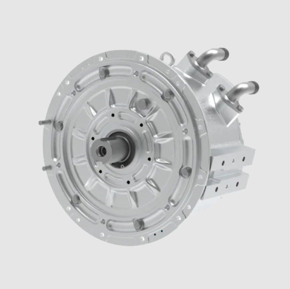
1. Vector Control of the Permanent Magnet Synchronous Motor
Vector control of a permanent magnet synchronous motor decomposes the stator current into a flux-producing component and a torque-producing component in the synchronous rotating d-q reference frame. By aligning the d-axis with the rotor permanent magnet flux, the control problem becomes similar to that of a separately excited DC motor. For a surface-mounted permanent magnet synchronous motor, the d-axis and q-axis inductances are equal, which simplifies the mathematical model. I use the d-q coordinate system to design the speed controller because it allows independent control of flux and torque.
The voltage equations of the permanent magnet synchronous motor in the d-q reference frame are expressed as
$$u_d = R i_d + \frac{d\psi_d}{dt} – \omega_e \psi_q$$
$$u_q = R i_q + \frac{d\psi_q}{dt} + \omega_e \psi_d$$
where \(u_d\) and \(u_q\) are the d-axis and q-axis stator voltages, \(i_d\) and \(i_q\) are the d-axis and q-axis stator currents, \(\psi_d\) and \(\psi_q\) are the d-axis and q-axis stator flux linkages, \(R\) is the stator resistance, and \(\omega_e\) is the electrical angular speed. The stator flux linkage equations are
$$\psi_d = L_d i_d + \psi_f$$
$$\psi_q = L_q i_q$$
In these equations, \(L_d\) and \(L_q\) are the d-axis and q-axis inductances, and \(\psi_f\) is the permanent magnet flux linkage. Substituting the flux linkage equations into the voltage equations yields the voltage equations in terms of currents:
$$u_d = R i_d + L_d \frac{di_d}{dt} – \omega_e L_q i_q$$
$$u_q = R i_q + L_q \frac{di_q}{dt} + \omega_e (L_d i_d + \psi_f)$$
The electromagnetic torque of a three-phase permanent magnet synchronous motor is
$$T_e = \frac{3}{2} p_n i_q \left[ i_d (L_d – L_q) + \psi_f \right]$$
where \(p_n\) is the number of pole pairs. For a surface-mounted permanent magnet synchronous motor, \(L_d = L_q = L_s\), so the reluctance torque term vanishes. The electromagnetic torque becomes
$$T_e = \frac{3}{2} p_n \psi_f i_q$$
The mechanical dynamics of the permanent magnet synchronous motor are governed by
$$J \frac{d\omega_m}{dt} = T_e – T_L – B \omega_m$$
where \(J\) is the rotational inertia, \(\omega_m\) is the mechanical angular speed, \(T_L\) is the load torque, and \(B\) is the viscous damping coefficient. The relationship between electrical and mechanical variables is
$$\omega_e = p_n \omega_m$$
$$N_r = \frac{30}{\pi} \omega_m$$
$$\theta_e = \int \omega_e dt$$
where \(N_r\) is the rotor speed in revolutions per minute and \(\theta_e\) is the electrical rotor angle. In the vector control scheme, I set the d-axis reference current to zero, i.e., \(i_d^* = 0\), so that the permanent magnet flux is not weakened and the stator current is used primarily for torque production. The q-axis current reference \(i_q^*\) is generated by the speed controller. The overall control structure includes a speed loop, d-axis and q-axis current loops, Park transformations, Clark transformation, space vector pulse width modulation, a three-phase inverter, and the permanent magnet synchronous motor.
2. Sliding Mode Speed Controller Design
Sliding mode control is a variable-structure control method that drives the system state onto a predefined sliding surface and maintains it there. The design procedure consists of selecting a sliding surface, choosing a reaching law, and deriving the control law. The permanent magnet synchronous motor speed tracking error is defined as
$$x_1 = \omega_{ref} – \omega_m$$
$$x_2 = \dot{x}_1 = -\dot{\omega}_m$$
where \(\omega_{ref}\) is the reference mechanical angular speed. Differentiating the state variables with respect to time gives
$$\dot{x}_1 = -\dot{\omega}_m = \frac{1}{J} \left( T_L – \frac{3 p_n \psi_f}{2} i_q \right)$$
$$\dot{x}_2 = -\ddot{\omega}_m = -\frac{3 p_n \psi_f}{2 J} \dot{i}_q$$
I define the lumped parameter
$$D = \frac{3 p_n \psi_f}{2 J}$$
and the control input
$$u = \dot{i}_q$$
Then the state-space representation of the permanent magnet synchronous motor speed error system becomes
$$\begin{bmatrix} \dot{x}_1 \\ \dot{x}_2 \end{bmatrix} = \begin{bmatrix} 0 & 1 \\ 0 & 0 \end{bmatrix} \begin{bmatrix} x_1 \\ x_2 \end{bmatrix} + \begin{bmatrix} 0 \\ -D \end{bmatrix} u$$
The sliding surface is selected as
$$s = c x_1 + x_2$$
where \(c\) is a positive constant that determines the sliding mode dynamics. Differentiating the sliding surface yields
$$\dot{s} = c \dot{x}_1 + \dot{x}_2 = c x_2 – D u$$
I use the exponential reaching law to ensure fast convergence and reduce chattering:
$$\dot{s} = -\varepsilon \operatorname{sgn}(s) – q s, \quad \varepsilon > 0, \quad q > 0$$
where \(\varepsilon\) and \(q\) are the reaching law parameters, and \(\operatorname{sgn}(\cdot)\) is the sign function. Equating the derivative of the sliding surface to the reaching law gives
$$c x_2 – D u = -\varepsilon \operatorname{sgn}(s) – q s$$
Solving for the control input \(u\) yields
$$u = \frac{1}{D} \left[ c x_2 + \varepsilon \operatorname{sgn}(s) + q s \right]$$
Since \(u = \dot{i}_q\), the q-axis current reference is obtained by integration:
$$i_q^* = \frac{1}{D} \int_0^t \left[ c x_2 + \varepsilon \operatorname{sgn}(s) + q s \right] d\tau$$
The stability of the sliding mode can be verified by considering the Lyapunov function
$$V = \frac{1}{2} s^2$$
Its time derivative is
$$\dot{V} = s \dot{s} = s \left[ -\varepsilon \operatorname{sgn}(s) – q s \right] = -\varepsilon |s| – q s^2 < 0$$
for \(s \neq 0\). Therefore, the reaching condition \(s \dot{s} < 0\) is satisfied, and the system states converge to the sliding surface in finite time. The parameters \(c\), \(q\), and \(\varepsilon\) strongly influence the response speed, overshoot, and chattering level. In conventional design, these parameters are often selected by trial and error. In this study, I use the fruit fly optimization algorithm to determine them automatically.
3. Fruit Fly Optimization Algorithm
The fruit fly optimization algorithm is a swarm intelligence method inspired by the foraging behavior of fruit flies. Fruit flies use their olfactory sense to locate food sources and their visual sense to move toward the best position. The algorithm has few parameters, low computational cost, and high search accuracy. The main steps of the fruit fly optimization algorithm are as follows.
First, I initialize the fruit fly population size, the maximum number of iterations, the initial position, and the random search range. Second, each fruit fly performs an olfactory search by updating its position randomly:
$$X_i = X_{axis} + \Delta X_i$$
$$Y_i = Y_{axis} + \Delta Y_i$$
where \(X_i\) and \(Y_i\) are the coordinates of the \(i\)-th fruit fly, \(X_{axis}\) and \(Y_{axis}\) are the current best coordinates, and \(\Delta X_i\) and \(\Delta Y_i\) are random perturbations. Third, I compute the distance from each fruit fly to the origin:
$$D_i = \sqrt{X_i^2 + Y_i^2}$$
Fourth, I calculate the olfactory concentration judgment value:
$$S_i = \frac{1}{D_i}$$
Fifth, I evaluate the smell concentration, which is equivalent to the fitness function value:
$$Smell_i = f(S_i)$$
Sixth, I identify the fruit fly with the best smell concentration:
$$[bestSmell, bestIndex] = \max(Smell_i)$$
Seventh, I update the best position and let the swarm fly toward it:
$$X_{axis} = X_{bestIndex}$$
$$Y_{axis} = Y_{bestIndex}$$
These steps are repeated until the maximum number of iterations is reached. In this study, I use the fruit fly optimization algorithm to tune the sliding mode controller parameters \(c\), \(q\), and \(\varepsilon\). The fitness function is designed to penalize speed error, overshoot, and settling time. A typical integral time-weighted absolute error criterion is
$$J = \int_0^T t |e(t)| dt$$
where \(e(t) = \omega_{ref}(t) – \omega_m(t)\) is the speed error. I also include penalty terms for overshoot and control effort to obtain a balanced response:
$$J = \int_0^T t |e(t)| dt + w_1 \sigma + w_2 t_s + w_3 \int_0^T |u(t)| dt$$
where \(\sigma\) is the overshoot, \(t_s\) is the settling time, and \(w_1\), \(w_2\), and \(w_3\) are weighting factors. The optimization process searches for the parameter set that minimizes the fitness function. The optimized parameters are then used in the sliding mode speed controller of the permanent magnet synchronous motor.
4. FOA-Optimized Sliding Mode Controller for the PMSM Speed Loop
The fruit fly optimization algorithm is integrated with the sliding mode controller in the speed loop of the permanent magnet synchronous motor. The reference speed \(N_{ref}\) is compared with the actual speed \(N_m\), and the speed error is fed to the sliding mode controller. The fruit fly optimization algorithm adjusts \(c\), \(q\), and \(\varepsilon\) according to the fitness function. The output of the sliding mode controller is the q-axis current reference \(i_q^*\). The d-axis current reference is set to zero. The current controllers are conventional PI controllers, and the inverter is driven by space vector pulse width modulation.
The optimization procedure is summarized as follows. I initialize the fruit fly population and generate candidate values of \(c\), \(q\), and \(\varepsilon\). For each candidate set, I run the permanent magnet synchronous motor speed control model and compute the performance index. I rank the fruit flies by fitness, retain the best position, and update the swarm. This process continues until the termination condition is satisfied. The optimized parameters are then applied to the final simulation model.
I use MATLAB/Simulink to build the complete model. The permanent magnet synchronous motor is a surface-mounted machine used as a direct-drive in-wheel motor. The control system parameters are listed in Table 1.
| Parameter | Value |
|---|---|
| Rotational inertia \(J\) (kg·m²) | 0.001538954 |
| Number of pole pairs \(p_n\) | 4 |
| Permanent magnet flux linkage \(\psi_f\) (Wb) | 0.11439 |
| Stator inductances \(L_d\), \(L_q\) (mH) | 4.25 |
| Stator resistance \(R\) (Ω) | 0.00478 |
| Flux linkage \(\psi_f\) (Wb) | 0.114394 |
| Damping coefficient \(B\) (N·m·s) | 0.008 |
| DC-link voltage \(U_{dc}\) (V) | 311 |
| PWM sampling period \(T_s\) (s) | 0.00001 |
| PWM switching frequency \(f_{pwm}\) (kHz) | 6 |
| Maximum speed (r/min) | 2500 |
The speed adjustment standard used to evaluate the control performance is given in Table 2. These values provide a reference for overshoot, rise time, and settling time.
| Item | Overshoot | Speed response rise time | Speed adjustment time |
|---|---|---|---|
| Standard | Within 30% | 0.1 s | 0.4 s |
5. Simulation Results and Analysis
I evaluate the proposed fruit fly optimization algorithm optimized sliding mode control method under three operating conditions. The first condition is no-load startup at a given speed. The second condition is sudden load application at a given speed. The third condition is load startup with a speed change. In each case, I compare the conventional sliding mode control and the fruit fly optimization algorithm optimized sliding mode control. The performance metrics include overshoot, rise time, adjustment time, recovery time, maximum dynamic variation, and electromagnetic torque response.
5.1 Case 1: No-Load Startup at 1000 r/min
In this case, the reference speed is set to 1000 r/min, and the permanent magnet synchronous motor starts without load. This condition emulates an electric vehicle accelerating to a target speed without external load. The purpose is to evaluate the response speed and overshoot of the two control methods. The speed response curves show that the fruit fly optimization algorithm optimized sliding mode control provides a smoother and faster response than conventional sliding mode control. The comparison is summarized in Table 3.
| Controller | Overshoot (%) | Speed response rise time (s) | Speed adjustment time (s) |
|---|---|---|---|
| Conventional SMC | 15.5 | 0.0075 | 0.0558 |
| FOA-SMC | 3.55 | 0.0079 | 0.0325 |
The results in Table 3 show that the overshoot decreases by approximately 77.09%, and the speed adjustment time decreases by approximately 41.7%. The rise time changes only slightly. This indicates that the fruit fly optimization algorithm can significantly reduce overshoot while maintaining a fast response. The optimized sliding mode controller tracks the reference speed with higher precision and less oscillation. For the permanent magnet synchronous motor, this improvement is important because excessive overshoot can cause mechanical stress and unnecessary current spikes.
I also observe that the fruit fly optimization algorithm optimized sliding mode control suppresses the chattering that is typically present in conventional sliding mode control. The chattering reduction is mainly due to the optimized reaching law parameters, which balance the discontinuous switching term and the proportional reaching term. The permanent magnet synchronous motor speed loop therefore becomes more suitable for practical electric vehicle applications.
5.2 Case 2: Sudden Load Application at 1000 r/min
In this case, the reference speed is 1000 r/min, and the initial load torque is 0 N·m. At \(t = 0.25\) s, the load torque suddenly changes to 4 N·m. This condition emulates an electric vehicle encountering a sudden load increase, such as climbing a slope or driving against wind resistance. The purpose is to test the disturbance rejection capability of the permanent magnet synchronous motor speed control system. The speed comparison is given in Table 4, and the torque comparison is given in Table 5.
| Controller | Overshoot (%) | Recovery time (s) | Speed adjustment time (s) | Maximum dynamic variation (%) |
|---|---|---|---|---|
| Conventional SMC | 13.5 | 0.01855 | 0.0532 | 10.8 |
| FOA-SMC | 2.1 | 0.01835 | 0.0203 | 10.2 |
| Controller | Electromagnetic torque overshoot after sudden load | Torque adjustment time before sudden load (s) | Torque adjustment time after sudden load (s) |
|---|---|---|---|
| Conventional SMC | 0.6306 | 0.0406 | 0.0301 |
| FOA-SMC | 0.4656 | 0.0185 | 0.0129 |
From Table 4, the overshoot under fruit fly optimization algorithm optimized sliding mode control is reduced from 13.5% to 2.1%, an improvement of about 84.4% relative to the conventional value. The speed adjustment time is reduced from 0.0532 s to 0.0203 s, an improvement of about 61.8%. The maximum dynamic variation is slightly reduced from 10.8% to 10.2%, an improvement of about 5.6%. The recovery time is nearly unchanged, but it remains within an acceptable range. These results indicate that the fruit fly optimization algorithm optimized sliding mode controller responds faster to load disturbances and restores the speed with less oscillation.
From Table 5, the electromagnetic torque response also improves. The torque adjustment time before the sudden load is reduced from 0.0406 s to 0.0185 s, an improvement of about 54.4%. The torque adjustment time after the sudden load is reduced from 0.0301 s to 0.0129 s, an improvement of about 57.1%. The electromagnetic torque overshoot after the sudden load is reduced from 0.6306 to 0.4656, an improvement of about 26.2%. These results confirm that the optimized sliding mode controller provides better torque regulation and reduces transient oscillations in the permanent magnet synchronous motor.
The conventional sliding mode control exhibits larger torque fluctuations and a wider speed variation range after the load change. In contrast, the fruit fly optimization algorithm optimized sliding mode control produces smaller torque fluctuations and a narrower speed variation range. This demonstrates the strong anti-interference capability of the proposed method for the permanent magnet synchronous motor drive.
5.3 Case 3: Load Start and Speed Change
In this case, the permanent magnet synchronous motor starts with a load torque of 4 N·m, and the reference speed is 1000 r/min. At \(t = 0.25\) s, the reference speed increases from 1000 r/min to 1100 r/min. This condition emulates an electric vehicle starting with a load and then accelerating to a higher target speed. The purpose is to evaluate the speed regulation capability of the two controllers. The comparison is shown in Table 6.
| Controller | Overshoot before speed change (%) | Adjustment time before speed change (s) | Overshoot after speed change (%) | Adjustment time after speed change (s) |
|---|---|---|---|---|
| Conventional SMC | 18.9 | 0.061 | 6.4 | 0.016 |
| FOA-SMC | 2.4 | 0.023 | 3.9 | 0.012 |
From Table 6, during the load-start phase, the fruit fly optimization algorithm optimized sliding mode control reduces the overshoot from 18.9% to 2.4%, an improvement of about 87.3%. The adjustment time is reduced from 0.061 s to 0.023 s, an improvement of about 62.3%. During the speed-change phase, the overshoot is reduced from 6.4% to 3.9%, an improvement of about 39%, and the adjustment time is reduced from 0.016 s to 0.012 s, an improvement of about 25%. These results show that the proposed controller provides better speed regulation performance for the permanent magnet synchronous motor under both load startup and acceleration conditions.
The conventional sliding mode control exhibits larger overshoot and longer settling time when the load is present. The fruit fly optimization algorithm optimized sliding mode control maintains a smoother speed trajectory and reaches the new reference speed with less oscillation. This is particularly important for an in-wheel permanent magnet synchronous motor because the direct-drive configuration is sensitive to torque ripples and speed fluctuations.
5.4 Summary of Improvements
To provide a clear comparison, I summarize the main improvements of the fruit fly optimization algorithm optimized sliding mode control over conventional sliding mode control in Table 7. The improvements are calculated based on the simulation results from the three operating conditions.
| Operating condition | Performance metric | Improvement |
|---|---|---|
| No-load startup at 1000 r/min | Overshoot reduction | 77.09% |
| No-load startup at 1000 r/min | Speed adjustment time reduction | 41.7% |
| Sudden load application | Overshoot reduction | 84.4% |
| Sudden load application | Speed adjustment time reduction | 61.8% |
| Sudden load application | Torque adjustment time reduction before load | 54.4% |
| Sudden load application | Torque adjustment time reduction after load | 57.1% |
| Sudden load application | Torque overshoot reduction | 26.2% |
| Load start with speed change | Overshoot reduction before speed change | 87.3% |
| Load start with speed change | Adjustment time reduction before speed change | 62.3% |
| Load start with speed change | Overshoot reduction after speed change | 39% |
| Load start with speed change | Adjustment time reduction after speed change | 25% |
The results in Table 7 indicate that the proposed method consistently improves the speed response and disturbance rejection of the permanent magnet synchronous motor. The largest improvements are observed in overshoot reduction, which is critical for protecting the mechanical transmission and reducing current peaks. The torque response also improves significantly, especially in the sudden load condition. The fruit fly optimization algorithm efficiently searches for the sliding mode parameters and avoids the tedious manual tuning process.
6. Discussion
The simulation results demonstrate that the fruit fly optimization algorithm optimized sliding mode controller has several advantages for the speed loop of a permanent magnet synchronous motor. First, the optimized reaching law parameters reduce the chattering caused by the discontinuous sign function. Chattering is a well-known problem in sliding mode control because it can excite unmodeled dynamics and increase power losses. By optimizing \(c\), \(q\), and \(\varepsilon\), the controller achieves a smoother control signal while maintaining robustness. Second, the optimized sliding mode controller provides faster speed response and smaller overshoot than the conventional sliding mode controller. This is because the fruit fly optimization algorithm finds a better trade-off between the reaching speed and the switching gain.
Third, the proposed controller exhibits strong anti-interference capability. When the load torque changes suddenly, the optimized sliding mode controller restores the speed quickly and with less oscillation. This is important for an in-wheel permanent magnet synchronous motor because the motor is directly connected to the wheel and is subject to road disturbances, load variations, and parameter changes. Fourth, the fruit fly optimization algorithm is simple and computationally efficient. It requires only a few parameters and can be implemented offline or online. In this study, I use offline optimization to obtain the controller parameters, which are then embedded in the MATLAB/Simulink model.
The mathematical model of the permanent magnet synchronous motor used in this study is based on the d-q reference frame. The assumptions include symmetrical three-phase windings, negligible core saturation, and sinusoidal back electromotive force. These assumptions are common in permanent magnet synchronous motor control design. The sliding mode controller is designed for the speed loop, while the current loops use PI controllers. This hierarchical structure is widely used in electric vehicle motor drives because it separates the slower speed dynamics from the faster current dynamics.
The fruit fly optimization algorithm fitness function includes the integral time-weighted absolute error and penalty terms for overshoot and settling time. The choice of weighting factors affects the optimized parameters and the resulting performance. In this study, I selected the weighting factors to prioritize overshoot reduction and settling time. The optimization process converges quickly and produces a stable set of parameters. The optimized sliding mode controller satisfies the speed adjustment standard given in Table 2.
One important aspect of the permanent magnet synchronous motor speed control is the interaction between the speed loop and the current loop. The output of the sliding mode controller is the q-axis current reference, which must be limited to protect the inverter and the motor. In the simulation, I apply current limiting to avoid excessive currents during transient conditions. The fruit fly optimization algorithm optimized sliding mode controller produces a smoother current reference, which reduces the stress on the inverter and improves the overall efficiency of the permanent magnet synchronous motor drive.
7. Conclusion
In this study, I designed and simulated a fruit fly optimization algorithm optimized sliding mode controller for the speed loop of an in-wheel permanent magnet synchronous motor used in a pure electric vehicle. I established the d-q mathematical model of the permanent magnet synchronous motor, derived the sliding mode controller with an exponential reaching law, and used the fruit fly optimization algorithm to tune the sliding surface coefficient and the reaching law parameters. The MATLAB/Simulink simulation model was built to evaluate the controller under no-load startup, sudden load application, and load start with speed change.
The simulation results show that the proposed fruit fly optimization algorithm optimized sliding mode controller achieves faster speed response, lower overshoot, shorter adjustment time, and stronger disturbance rejection than the conventional sliding mode controller. In the no-load startup condition, the overshoot is reduced by 77.09%, and the speed adjustment time is reduced by 41.7%. In the sudden load condition, the speed overshoot is reduced by 84.4%, and the speed adjustment time is reduced by 61.8%. The electromagnetic torque adjustment time is reduced by 54.4% before the sudden load and by 57.1% after the sudden load, while the torque overshoot is reduced by 26.2%. In the load start with speed change condition, the overshoot before the speed change is reduced by 87.3%, and the adjustment time is reduced by 62.3%. After the speed change, the overshoot is reduced by 39%, and the adjustment time is reduced by 25%.
These results confirm that the fruit fly optimization algorithm is an effective method for tuning the sliding mode controller of a permanent magnet synchronous motor. The proposed controller reduces chattering, improves speed regulation, and enhances the robustness of the permanent magnet synchronous motor drive. For an in-wheel permanent magnet synchronous motor in a pure electric vehicle, the improved speed loop control can contribute to better drivability, lower energy consumption, and higher reliability. In future work, I plan to consider parameter uncertainties, temperature effects, and hardware-in-the-loop validation to further verify the practical applicability of the proposed method.
Overall, the combination of sliding mode control and the fruit fly optimization algorithm provides a promising solution for the speed control of permanent magnet synchronous motors in electric vehicle applications. The permanent magnet synchronous motor remains a key enabling technology for electrified transportation, and advanced control algorithms such as the one presented here can help unlock its full performance potential.