
As a researcher focused on advancing control systems for electric vehicle safety, I present a comprehensive study on the application of Radial Basis Function (RBF) Neural Network-based Sliding Mode Variable Structure Control (SMC) to enhance the hydraulic pressure regulation of Electronic Braking Systems (EBooster) in electric vehicles. Traditional PID controllers often struggle with nonlinearities and disturbances inherent in electric vehicle braking dynamics. This work establishes a robust framework integrating RBF’s adaptive approximation capability with SMC’s disturbance rejection to achieve superior pressure tracking.
1. System Modeling and Challenges in Electric Vehicles
Electric vehicle EBooster systems convert motor torque into hydraulic pressure through a transmission mechanism. The critical dynamics are governed by:
\dot{p} = \frac{1}{\beta_e V} \left( Q - A_p \dot{x}_p \right)
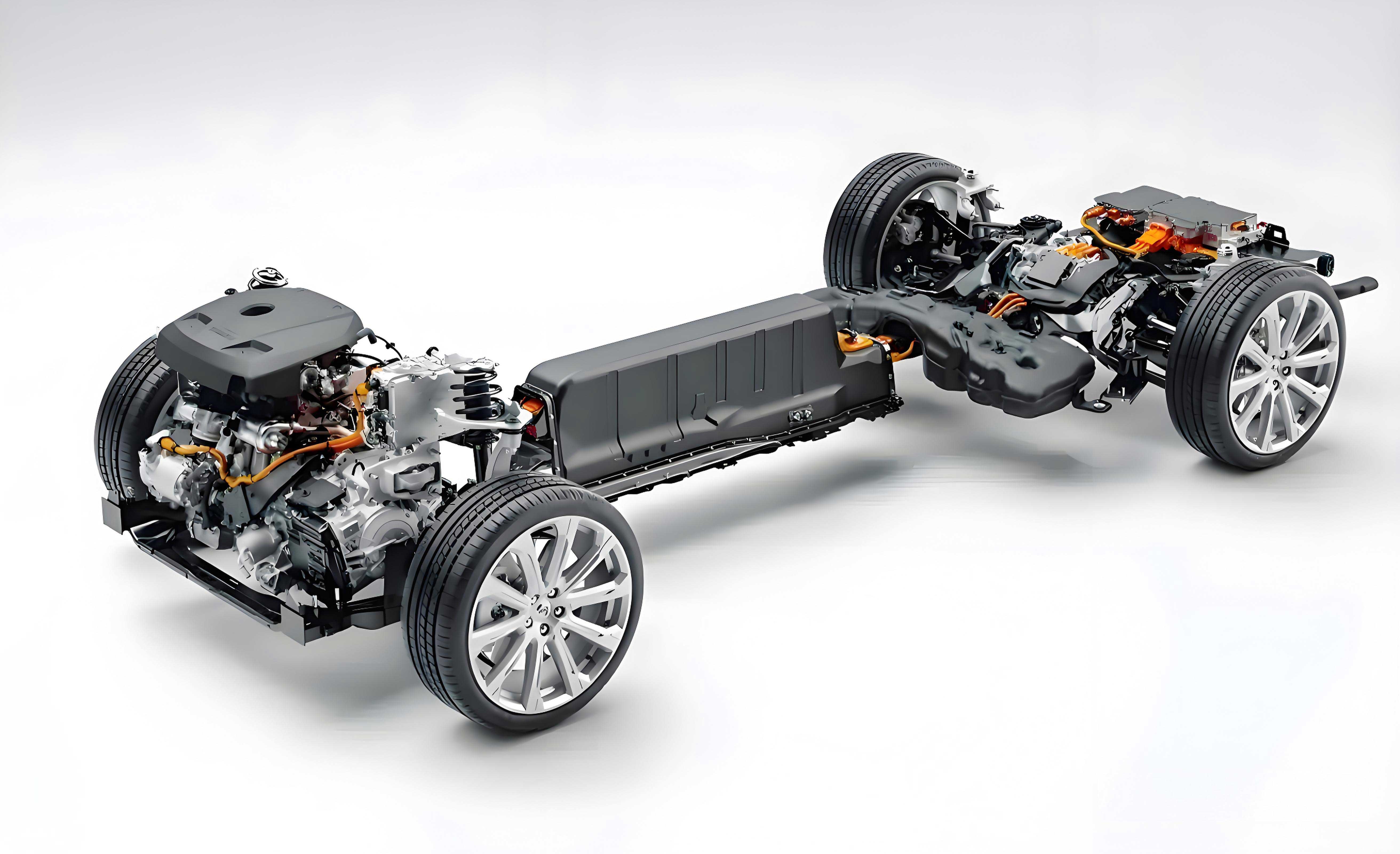
where $p$ is hydraulic pressure, $\beta_e$ is fluid bulk modulus, $V$ is control volume, $Q$ is flow rate, $A_p$ is piston area, and $\dot{x}_p$ is piston velocity. The transmission mechanism (Fig. 1) introduces nonlinearities from gear backlash and friction, exacerbated by electric vehicle regenerative braking interactions.
Table 1: Transmission Mechanism Parameters
| Parameter | Symbol | Value | Unit |
|---|---|---|---|
| Piston Area | $A_p$ | $4.2 \times 10^{-4}$ | m² |
| Gear Ratio | $r$ | 3.2 | – |
| Lead | $h$ | $87.6 \times 10^{-3}$ | m |
| Motor Shaft Inertia | $J_M$ | $8.8 \times 10^{-5}$ | kg·m² |
| Translational Mass | $m$ | 0.5 | kg |
| Spring Stiffness | $K$ | 4.5 | kN/m |
2. RBF-SMC Controller Design
The RBF network approximates unknown system dynamics online, enabling adaptive SMC parameter tuning. The network structure (1-4-3: 1 input, 4 hidden neurons, 3 outputs) uses Gaussian basis functions:
h_j(p) = \exp \left( -\frac{\| p - c_j \|^2}{2b_j^2} \right), \quad j=1,2,3,4
where $c_j$ is the center and $b_j$ the width of the $j$-th neuron. The RBF outputs approximate $f(p)$ and $g(p)$:
\hat{f}(p) = \mathbf{W}^T \mathbf{h}(p), \quad \hat{g}(p) = \mathbf{V}^T \mathbf{h}(p)
The sliding surface and control law are designed as:
\begin{align}
s &= c_1 e + c_2 \dot{e}, \quad e = p - p_{ref} \\
\dot{s} &= -k \cdot \text{sat}(s/\phi) - q s
\end{align}
where $\mathbf{W}, \mathbf{V}$ adapt via $\dot{\mathbf{W}} = -\gamma_1 s \mathbf{h}(p)$, $\dot{\mathbf{V}} = -\gamma_2 s \mathbf{h}(p) u$.
Table 2: RBF-SMC Controller Parameters
| Parameter | Symbol | Value |
|---|---|---|
| Sliding Coefficients | $c_1, c_2$ | 7.2, 3.6 |
| Reaching Law Gains | $k, q$ | 15.2, 0.09 |
| Boundary Layer | $\phi$ | 1 |
| RBF Width | $b_j$ | 0.16 |
| Adaptive Gains | $\gamma_1, \gamma_2$ | 6.8, 7.6 |
3. Simulation Results for Electric Vehicle Scenarios
Tests under sinusoidal pressure tracking (3 MPa amplitude, 1.25 Hz) demonstrate RBF-SMC’s superiority over PID:
- Steady-State Error: RBF-SMC: < 0.1 MPa vs. PID: ±0.3 MPa
- Overshoot: RBF-SMC: 0% vs. PID: 66% at 5 MPa step input
- Error Relative Value: RBF-SMC: < 2% across electric vehicle operating ranges.
\text{Relative Error} = \frac{|p - p_{ref}|}{p_{ref}} \times 100\%
Table 3: Performance Comparison (Sinusoidal Tracking)
| Metric | PID | RBF-SMC |
|---|---|---|
| Max Absolute Error | 0.30 MPa | 0.08 MPa |
| RMS Error | 0.17 MPa | 0.04 MPa |
| Settling Time (5 MPa) | 0.45 s | 0.20 s |
4. Real-World Electric Vehicle Validation
The controller was tested on an electric vehicle platform under Adaptive Cruise Control (ACC) and Automatic Emergency Braking (AEB) scenarios (0–10 m/s, 8 MPa max pressure). Key outcomes:
- Slope Conditions: Zero overshoot/jitter, error < 0.1 MPa.
- Hydraulic Load Variations: RBF adaptation maintained < 1.5% relative error.
- Robustness: Unaffected by electric vehicle mass fluctuations (1,620 kg test vehicle).
Table 4: AEB Test Performance (0–10 m/s)
| Condition | Overshoot | Settling Time | Steady-State Error |
|---|---|---|---|
| Dry Asphalt | 0% | 0.25 s | 0.07 MPa |
| Wet Surface | 0% | 0.28 s | 0.09 MPa |
| Regenerative Braking Active | 0% | 0.30 s | 0.10 MPa |
5. Conclusion
This RBF-SMC framework achieves high-precision hydraulic pressure control for electric vehicle EBooster systems, critical for ACC/AEB safety. By combining RBF’s nonlinear approximation with SMC’s robustness, it eliminates chattering and maintains errors within 0.1 MPa (<2%) under dynamic electric vehicle conditions. Future work will integrate this controller with electric vehicle braking energy recovery systems.
Appendix: Nomenclature
| Symbol | Definition |
|---|---|
| $p$ | Hydraulic pressure |
| $\beta_e$ | Fluid bulk modulus |
| $A_p$ | Piston area |
| $\text{sat}(\cdot)$ | Saturation function |
| $p_{ref}$ | Target pressure |