
As an experienced technician specializing in electric vehicle repair, I have witnessed the rapid evolution of新能源汽车驱动系统 and the increasing complexity of their maintenance. In the context of global efforts to reduce carbon emissions, electric vehicles (EVs) have become a cornerstone of sustainable transportation. However, their drive systems, which are central to vehicle performance, present unique challenges in EV repair. This article delves into the intricacies of新能源汽车驱动系统维修技术, focusing on common故障问题 and practical solutions, all from my first-hand perspective. I will explore the structural components, analyze specific故障案例, and emphasize safety protocols, while incorporating formulas and tables to summarize key points. Throughout, I aim to highlight the importance of electrical car repair in ensuring vehicle reliability and safety.
The drive system in an electric vehicle is the heart of its operation, directly influencing driving dynamics and safety. From my work in EV repair, I know that it primarily consists of the drive motor and the motor controller. The drive motor serves as the power source, executing driver commands, while the motor controller regulates power output and maintains communication with the vehicle control unit (VCU). Additionally, components like temperature sensors and resolvers are integrated into the motor to monitor conditions and provide feedback. Understanding this structure is crucial for effective electrical car repair, as any malfunction can lead to significant issues such as abnormal vibrations or power loss. In my experience, a thorough grasp of these elements allows technicians to diagnose problems accurately and perform repairs that align with industry standards.
In新能源汽车驱动系统维修技术, one common issue I encounter is abnormal vehicle vibration. This often manifests as intense shaking, reduced acceleration, and unusual noises, which can compromise driving safety. Based on my observations in EV repair, such vibrations typically stem from mechanical imbalances or electrical faults. For instance, loose motor mounting bolts or rotor misalignment can induce resonance, while bearing wear or controller anomalies might exacerbate the problem. To diagnose this, I follow a systematic approach: first, I conduct a基础性检查 to verify bolt tightness and structural integrity; second, I use vibration analysis tools to locate the vibration source, assessing amplitude and frequency; third, I perform电气检测 with diagnostic scanners to check for fault codes and analyze three-phase current and voltage waveforms; and finally, I inspect mechanical parts like rotors and bearings for wear or contamination. This method ensures a comprehensive assessment in electrical car repair.
To illustrate the diagnostic process for abnormal vibration in EV repair, I often use formulas to quantify vibrations. For example, the vibration amplitude $A$ can be related to the force $F$ and stiffness $k$ of the system by the equation: $$A = \frac{F}{k}$$ where $F$ might represent unbalanced forces from the motor. Additionally, the natural frequency $f_n$ of a component can be calculated as: $$f_n = \frac{1}{2\pi} \sqrt{\frac{k}{m}}$$ where $m$ is the mass. If the operating frequency matches $f_n$, resonance occurs, leading to excessive vibrations. In practice, I measure these parameters to identify imbalances and recommend corrective actions, such as rotor balancing or bolt tightening.
| Check Type | Procedure | Tools Used | Common Findings in EV Repair |
|---|---|---|---|
| Basic Inspection | Verify motor bolts and connections | Torque wrench | Loose bolts, misalignment |
| Vibration Source Location | Measure amplitude and frequency | Vibration analyzer | Resonance from rotor imbalance |
| Electrical Detection | Scan for fault codes, analyze waveforms | Diagnostic tool, oscilloscope | Abnormal current patterns |
| Mechanical Check | Inspect rotor and bearings | Micrometer, visual inspection | Wear, excessive游隙 |
Another frequent issue in新能源汽车驱动系统维修技术 is motor overspeed, where the motor rotates beyond safe limits, potentially causing damage. In my electrical car repair practice, I have found that this often results from sensor failures or controller malfunctions. For example, an加速踏板位置传感器 (APS) with signal drift can send erroneous commands to the controller, prompting excessive转速. Similarly, resolver faults or mechanical disconnections in the传动系统 can reduce resistance and lead to sudden acceleration. To diagnose this, I rely on fault codes like “P0123” or “P0500” from the motor controller (MCU) and VCU, and then test sensor outputs and connections. Formulas play a key role here; for instance, the relationship between motor speed $\omega$ in rad/s and rotational speed $N$ in RPM is given by: $$\omega = \frac{2\pi N}{60}$$ By monitoring these values, I can detect anomalies and take corrective measures, such as replacing sensors or recalibrating systems.
| Fault Cause | Diagnostic Method | Repair Action in EV Repair | Prevention Tips |
|---|---|---|---|
| APS Signal Drift | Check voltage output with multimeter | Replace accelerator pedal assembly | Regular sensor calibration |
| Controller Failure | Analyze output signals | Repair or replace controller | Update firmware |
| Resolver Fault | Inspect wiring and connections | Reinstall and calibrate resolver | Maintain proper air gap (0.1–0.3 mm) |
| Mechanical Disconnection | Visual inspection of传动系统 | Adjust gear engagement | Routine checks |
In more severe cases, I have dealt with controller IGBT breakdowns that result in complete power loss, a critical scenario in EV repair. For instance, a vehicle might display “Check Power System” and enter limp mode due to overcurrent or overheating. From my experience, this is often caused by硬件缺陷 like short circuits in the IGBT modules or冷却系统 failures. Using diagnostic tools, I retrieve codes such as “P1A49” for overcurrent protection and “P0A7F” for high IGBT temperature. Then, I perform硬件检测 with a multimeter to measure resistances—for example, if the U-phase upper arm shows 0 Ω, it indicates a short circuit. The current $I$ in such cases can be modeled by Ohm’s law: $$I = \frac{V}{R}$$ where $V$ is voltage and $R$ is resistance. If $R$ approaches zero, $I$ spikes, leading to damage. Additionally, thermal management is crucial; the heat dissipation can be described by: $$Q = mc\Delta T$$ where $Q$ is heat, $m$ is mass, $c$ is specific heat, and $\Delta T$ is temperature change. In repairs, I replace IGBT modules using vacuum reflow soldering for better connectivity, clean cooling ducts, and update controller software to optimize thresholds.
| Fault Code | Description | Measurement in EV Repair | Corrective Action |
|---|---|---|---|
| P1A49 | Motor controller overcurrent | Current peak up to 800 A | Replace IGBT, optimize software |
| P0A7F | IGBT module overtemperature | Temperature >105°C (normal <85°C) | Clean fans, apply thermal paste |
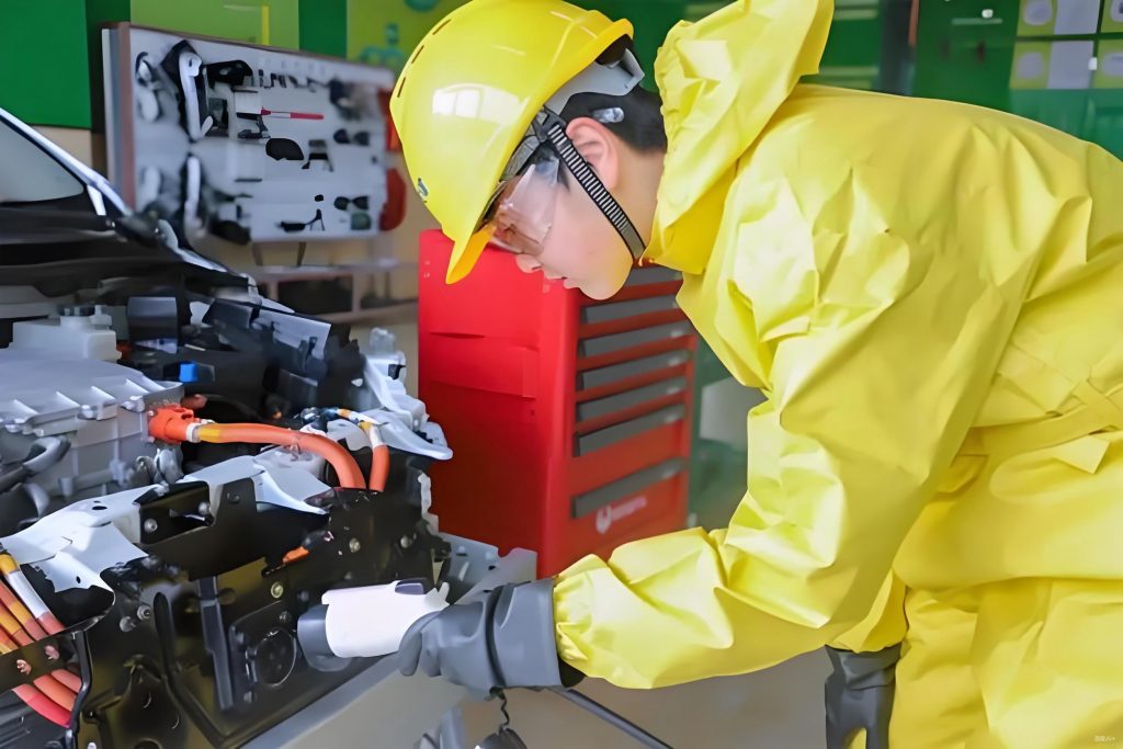
Safety is paramount in新能源汽车驱动系统维修技术, and I always adhere to strict protocols during electrical car repair. Before any work, I ensure the vehicle is powered down and discharged, especially for high-voltage components. I use CAT III 1000 V insulated tools and avoid metal instruments near live parts. For instance, when disassembling motors, I insulate exposed terminals with tape to prevent shorts. Personal protective equipment (PPE) like insulated gloves and shoes is mandatory, and I lay绝缘垫 in the work area. When handling controllers, I carefully install IGBT modules and apply导热硅脂 to ensure even heat distribution. These practices not only protect me but also enhance the reliability of repairs, reducing the risk of recurring issues in EV repair.
In summary, my approach to新能源汽车驱动系统维修技术 revolves around a three-tier diagnostic framework: signal, control, and mechanical aspects. I start by verifying signals from sensors like the accelerator pedal and resolvers, then move to controller hardware and software checks, and finally inspect mechanical components for wear or misalignment. Using fault diagnostic tools, I quickly identify codes and correlate them with driver feedback to streamline the process. This methodology, combined with a emphasis on safety, allows for efficient and effective electrical car repair. As EVs continue to advance, mastering these techniques will be essential for technicians worldwide, ensuring that vehicles remain safe and operational on the road.
Throughout this discussion, I have integrated formulas and tables to encapsulate key concepts in EV repair. For example, the vibration analysis formula $$A = \frac{F}{k}$$ helps quantify mechanical issues, while the speed equation $$\omega = \frac{2\pi N}{60}$$ aids in understanding overspeed scenarios. Tables summarize diagnostic steps and repair actions, providing a clear reference for practitioners. By repeatedly emphasizing terms like EV repair and electrical car repair, I aim to reinforce their importance in the industry. Ultimately, this comprehensive analysis underscores the need for continuous learning and adaptation in the field of electric vehicle maintenance.