
As an experienced automotive technician specializing in hybrid electric vehicle systems, I recently encountered a challenging case involving a 2019 model year hybrid electric vehicle. This incident highlights the complexities of diagnosing modern hybrid electric vehicle powertrains, where multiple systems interact in ways that can obscure the root cause of a fault. The vehicle in question was a mid-size sedan from a popular manufacturer, equipped with a 2.0L GDI Atkinson-cycle gasoline engine designed for hybrid applications, a dedicated 6-speed plug-in hybrid electric vehicle transmission, and a high-voltage traction battery system consisting of two separate packs with a total capacity of 12.9 kWh. The owner reported that while driving, the dashboard would display alerts such as “Check Hybrid System” or “Safely Stop and Turn Off Vehicle to Check Hybrid System,” accompanied by the illumination of the hybrid system and engine warning lamps. The vehicle would enter a limited-performance mode but remain drivable. Occasionally, upon coming to a stop, the READY state would deactivate, requiring a full power cycle to resume operation.
My initial approach with any hybrid electric vehicle diagnosis is a thorough preliminary inspection. With the ignition in the ON position, all systems performed a self-check without anomalies. Starting the vehicle and achieving READY state also showed no immediate issues. However, during a road test, a critical clue emerged. As soon as I shifted from Park into a drive gear (Reverse or Drive), a faint, continuous high-frequency “squeal” became audible from the rear of the vehicle, near the traction battery compartment. This noise is not typical for a properly functioning hybrid electric vehicle. After several minutes of driving, the described fault manifested: the warning messages appeared, the warning lamps illuminated, and power was limited. The vehicle did not stall but clearly entered a fail-safe mode. On two occasions during the test, when stopping at a traffic light, the hybrid system shut down completely, exiting the READY state. A full key cycle was necessary to restart the hybrid electric vehicle’s propulsion system.
Connecting the dedicated diagnostic scanner revealed a web of trouble codes spread across several control modules, a common but intricate scenario in a hybrid electric vehicle. The Battery Management System (BMS) stored multiple codes pointing to voltage sensing circuit irregularities for various battery cell groups (e.g., P0B4A, P0B59) and a code for high-voltage battery temperature deviation (P1B97). The Central Gateway (CGW) logged a communication error with the BMS (B221100), and the Air Conditioning system registered a compressor operation fault (B1696). This combination suggested a core disruption in the high-voltage system’s data or power integrity.
Examining the live data stream from the BMS provided more concrete, yet puzzling, evidence. The total DC voltage of the traction battery was reading 6553.5V, which was plausible for this hybrid electric vehicle’s architecture. However, the temperature readings for battery modules 9 through 16 were reported as -56°C, a physically impossible value indicating a sensor or communication failure. Furthermore, these temperature and individual cell voltage values occasionally exhibited erratic jumps during monitoring.
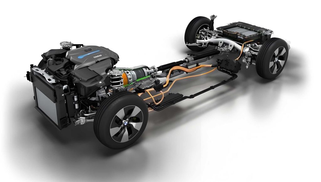
To understand the fault, one must grasp the network architecture of this hybrid electric vehicle’s battery system. The battery pack is divided into primary and secondary units. Each unit contains four modules, and each module houses 12 individual cells and two temperature sensors. All cells are connected in series. A Cell Monitoring Unit (CMU) inside each module measures voltage and temperature, and these data are communicated via a local battery CAN (Controller Area Network) bus to a Battery Management Unit (BMU), which then relays information to the central BMS module. The BMS, in turn, communicates with the vehicle’s main CAN networks (H-CAN and P-CAN) via the gateway. This layered communication is vital for the safe and efficient operation of any hybrid electric vehicle.
| Control Module | DTC | Description | Implied Fault Area |
|---|---|---|---|
| BMS | P0B4A, P0B59, P0B5E, P0B54, P0B4F, P0B45 | Hybrid Battery Voltage Sense Circuit “D, G, H, F, E, C” | Battery Modules, CMUs, Wiring Harness |
| BMS | P1B97 | High Voltage Battery Temperature Deviation | Temperature Sensors, CMUs, Communication |
| CGW | B221100 | CAN Communication with BMS Interrupted | BMS Power, CAN Bus Wiring |
| AIRCON | B1696 | Compressor Operation State Fault | Electric Compressor, High-Voltage Supply, CAN Signal |
The logical first step was to inspect the high-voltage battery pack and its connections for physical damage, corrosion, or looseness. No external issues were found. Given the communication errors, I proceeded to probe the battery CAN network with an oscilloscope. The waveform was aberrant. A healthy high-speed CAN signal should have clean, symmetrical square waves with specific minimum and maximum voltage levels. The captured waveform showed irregular patterns and deviations in voltage levels, indicating severe signal integrity problems on the network.
$$V_{CAN\_H}(ideal) \approx 2.5V \ to \ 3.5V$$
$$V_{CAN\_L}(ideal) \approx 1.5V \ to \ 2.5V$$
$$V_{DIFF} = V_{CAN\_H} – V_{CAN\_L}$$
The measured waveforms showed inconsistent $V_{DIFF}$ and non-standard switching patterns, confirming corruption.
My initial hypothesis centered on a faulty battery module, BMU, or the BMS module itself. To isolate the issue, I swapped the entire battery pack assembly and later the BMS module with known-good units from a donor vehicle. To my frustration, the fault persisted. I then addressed the air conditioning compressor fault code (B1696). Measurements of the high-voltage supply to the compressor, its CAN communication lines, and insulation resistance between the high-voltage terminals and chassis all returned normal values. Replacing the electric compressor also yielded no change. The diagnosis had reached an impasse.
This is where deep system knowledge of a hybrid electric vehicle becomes paramount. The battery CAN network is a shielded, twisted-pair system designed for high noise immunity. For its signal to be so profoundly distorted, the source of interference had to be powerful and likely within the high-voltage system itself. I revisited the principle: when all logical paths are exhausted, consider electromagnetic interference or unexpected interactions between systems. All high-voltage components in a hybrid electric vehicle are potential sources of noise if compromised.
I decided to perform insulation resistance tests on all major high-voltage components: the battery pack itself, the power relay assembly (PRA), the inverter, and the traction motor. The insulation resistance for the high-voltage bus from the battery was well above the required minimum (typically >10 MΩ). However, when testing the three-phase windings (U, V, W) of the drive motor against its metal casing, I discovered the critical fault.
| Component | Test Point (to Chassis) | Measured Resistance | Specification (Minimum) | Status |
|---|---|---|---|---|
| Traction Battery Pack | Positive (+) Terminal | >500 MΩ | >10 MΩ | OK |
| Traction Battery Pack | Negative (-) Terminal | >500 MΩ | >10 MΩ | OK |
| Electric A/C Compressor | HV+ Terminal | >100 MΩ | >10 MΩ | OK |
| Drive Motor (Phase U) | Winding Terminal | ~416 kΩ | >10 MΩ | FAIL |
| Drive Motor (Phase V) | Winding Terminal | ~410 kΩ | >10 MΩ | FAIL |
| Drive Motor (Phase W) | Winding Terminal | ~420 kΩ | >10 MΩ | FAIL |
The insulation resistance of the drive motor windings was only around 416 kΩ, far below the acceptable threshold. Furthermore, this value fluctuated and sometimes dropped lower as the motor’s temperature changed. The insulation was breaking down but was not yet a dead short. This condition created a significant leakage path to ground. The insulation resistance can be modeled by the formula:
$$R_{insulation} = \frac{V_{system}}{I_{leakage}}$$
Where $V_{system}$ is the operating voltage (e.g., ~650V) and $I_{leakage}$ is the current flowing through the insulation defect. With $R_{insulation}$ in the low hundreds of kΩ, $I_{leakage}$ becomes substantial enough to cause interference.
This finding explained the entire symptom chain. When the hybrid electric vehicle was started and placed in gear, the inverter began supplying pulsed high-voltage, high-current power to the drive motor windings. The compromised insulation caused uneven leakage currents to flow to the chassis ground. These leakage currents were not constant; they pulsed in sync with the inverter’s switching frequency, creating powerful electromagnetic interference (EMI). This EMI directly corrupted the sensitive analog and digital signals on the nearby battery CAN network, which runs in close proximity to the high-voltage cables and motor assembly.
The corrupted data on the battery CAN network led the BMS to perceive implausible sensor values (like -56°C temperatures) and communication faults, triggering the myriad of voltage and temperature DTCs. The intermittent communication breakdown between the BMS and the gateway triggered the CGW code. The noise on the power network may have also briefly disrupted the CAN messages for the air conditioning controller, causing it to log the compressor fault. The faint “squeal” heard from the rear was likely arcing or discharge noise within the Power Relay Assembly (PRA) as the leakage currents pulsed through the main contactors.
The reason a dedicated “High Voltage Insulation Fault” code (like P0AA6) was not set is insightful. The BMS typically performs an insulation check at key-on or during specific intervals by applying a test voltage and measuring leakage. In this hybrid electric vehicle, the motor windings are disconnected from the high-voltage bus during this test via relays in the PRA. Therefore, the BMS only tested the insulation of the battery and cables up to the PRA, which was intact. The motor’s insulation failure only manifested when the system was under load, with the relays closed and high-voltage AC being applied. The leakage current, while significant for causing interference, might not have exceeded the specific threshold programmed in the BMS to trigger a direct insulation fault code, as the system’s monitoring logic may have been overwhelmed by the primary communication errors.
Replacing the integrated drive motor and generator assembly resolved all issues. After the repair, the battery CAN waveform returned to normal, all diagnostic trouble codes cleared, and the hybrid electric vehicle operated flawlessly on extended road tests. The anomalous noises ceased, and the system alerts never reappeared.
This case underscores several critical lessons for technicians working on hybrid electric vehicle platforms:
1. System Interdependence: In a hybrid electric vehicle, a fault in one high-power component (the drive motor) can manifest as a seemingly unrelated fault in a low-power control network (the battery CAN). Diagnosing a hybrid electric vehicle requires thinking beyond linear cause-and-effect.
2. EMI as a Fault Source: Electromagnetic interference is a real and potent fault mode in high-voltage systems. When dealing with erratic communication or sensor data, especially on networks near power cables, consider EMI from a failing component like a motor or inverter.
3. Importance of Insulation Testing: Comprehensive insulation resistance testing of ALL high-voltage components—including the motor phases—is a crucial step when power or communication issues arise. The formula for leakage power dissipation, $P_{leakage} = \frac{V^2}{R_{insulation}}$, shows that even with several hundred kΩ of resistance, significant energy can be dissipated, causing heat and interference. For a system voltage of 650V, a 400 kΩ fault dissipates approximately:
$$P_{leakage} = \frac{(650)^2}{400 \times 10^3} = \frac{422500}{400000} \approx 1.06 \text{ Watts}$$
This continuous discharge is enough to generate notable interference.
4. Fluid Specifications Matter: This particular hybrid electric vehicle uses a wet-type oil-cooled permanent magnet synchronous motor. Using incorrect transmission fluid, which also serves as the motor coolant, can degrade insulation materials over time, leading to premature failure. Always adhere to the manufacturer’s specified fluids for a hybrid electric vehicle.
In conclusion, the successful repair of this hybrid electric vehicle hinged on moving from a component-oriented diagnosis to a system-level analysis. The hybrid electric vehicle’s complexity demands that technicians understand not just individual systems but how energy, data, and electromagnetic fields interact between them. This case reinforces that when standard diagnostic paths lead to a dead end in a hybrid electric vehicle, investigating potential sources of electrical noise and performing thorough insulation integrity checks on all high-voltage load components can reveal the true root cause.